设计说明书.doc

全自动V带分拣机的设计【6张CAD图纸和说明书】

收藏

资源目录
跳过导航链接。
全自动V带分拣机的设计【6张CAD图纸和说明书】.rar
设计说明书.doc---(点击预览)
登记表.doc---(点击预览)
申报表.doc---(点击预览)
小论文.doc---(点击预览)
A0-位移检测系统部件图.dwg
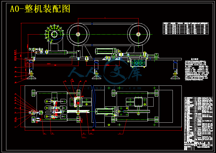
A0-整机装配图.dwg
A1-分辨率提高器.dwg
A2-气压系统原理图.dwg
A3-字头盘轴零件图.dwg
A3-检测带轮零件图.dwg
压缩包内文档预览:(预览前20页/共44页)
预览图 预览图 预览图 预览图 预览图 预览图 预览图 预览图 预览图 预览图 预览图 预览图 预览图 预览图 预览图 预览图 预览图 预览图 预览图 预览图
编号:10613713    类型:共享资源    大小:1.28MB    格式:RAR    上传时间:2018-09-02 上传人:俊****计 IP属地:江苏
40
积分
关 键 词:
全自动 分拣 设计 cad 图纸 以及 说明书 仿单
资源描述:

摘要


全自动V带分拣机是一种昂贵的高效能设备,所以在广大厂家中需要一种价格低廉又能够进行分拣工作的设备。本文介绍既能达到维修,调试,使用方便,又能达到高效能的一种半自动只能V带长度分拣机。主要研究内容有,设计了用于V带分拣,融PLC现代传感器技术机械气动于一体的机电一体化设备,利用现代传感技术,实现位移量于检测脉冲数之间的转换,通过对检测脉冲数分组,简介实现北侧带长的分组:组别标记号对应的打印脉冲次数,实现自动打印组别号标记。以PLC为控制核心部分实现智能化控制。根据V带日生产量大的特点,通过自动检测于打印一体化,实现了高效率检测。半自动智能的设计思想,使高科技于丰富人力资源实现了有机结合,适合国情。


关键词:分拣,PLC, 打印脉冲


Abstract

  The sort of V-belt is a wide-used product. It is difficult to accomplish it by hand and the Auto-Sorter is effective but too expensive. So most of the sorts are done by selective exams.in this case,an efficient convenient and cheap V-belt sorter is in bad need。In this dissertation, the semi-auto V-belt sorter is developed to meet this need. It is typical mechatronic equipment。Auto-mask is realized by using sensor, PLC is used as a main controlling section. The technique of auto-sort and auto-mark can meet the need of the rapid massive production .the semi-auto design can take advantage of the rich human resources, which is more adoptable in China.


Key words: sort  PLC  exam pulse


目录

Abstract 2

第1章 绪 论 4

1.1引言 4

1.2分组分拣技术与分组销售 5

1.2.1分组分拣技术与分组销售的问题描述及解决方案特点 5

2、分拣技术 5

1.2.2半自动智能v带长度分拣机技术分析 7

1.3现代控制技术、检测技术现状分析 8

1.3.1可编程控制器(PLC)国内应用现状 9

2.1 引言 10

2.2总体设计的主要内容 10

2.2.1 V带分组性能指标 11

2.2.2总体方案 12

(Ld=1400 mm)                            单位:mm 13

3.1引言 14

3.2位移检测 15

3.2.2.根据本机精度确定被测V带组段范围 16

3.2.3  分辨率提高器结构尺寸的设计 17

3.3自动打印标记 21

3.3.1  字头转动电机的选择 24

3.3.2  字头转动轴的设计 25

3.3.3  联轴器的选择 25

3.4设备各工作过程的控制 26

3.4.1 PLC控制特点及所选型号 27

4.1引言 28

4.2气动技术的主要特点 28

4.3气动装置设计 29

5.1引言 31

5.2检测带轮直径及结构设计 31

5.2.1固定式检测带轮 32

5.2.2夹紧式检测带轮 34

5.3初始中心距及基准中心距的确定、总自支架上的刻度 36

5.4检测带轮轴系以及机架设计 37

5.4.1  检测带轮轴的设计 37

(1).对导轨进行弯曲应力校核 41

5.6本章小节 43

参考文献 45

致    谢 46


第一章  绪 论

1.1引言

 带传动是一种应用很广的机械传动,其中V带产生的摩擦力要比普通平带大得多,因此v带的传动能力比普通平带高,目前V带在机械中获得广泛的应用。V带已标准化,根据国家标准的规定,普通V带按剖面尺寸不同,分为Y, Z, A, B, C,D, E七种型号,V带是无接头的环形带,每种型号都有几种不同的周长。标准中将内周长度定为公称长度,长度从400-1600mm不等[1]。由于受单根V带所能传递功率之限制,在传递较大功率时,往往设置多根V带成组使用。但一般要求,为避免载荷在各根带上分布不均匀,带的根数不宜过多,一般不应超过9根。

V带的伸张层与压缩层由橡胶制成,强力层可由几层帘布或线绳制成。其公称尺寸受生产工艺、原材料等因素影响较大。事实上,目前各类规模生产厂家生产的同一型号、同一公称尺寸V带的长度误差值均较大(可达几十毫米,这在金属制品中是不可想象的)。由此造成在成组使用多根V带的传动中,尽管选用了某生产厂家的同一型号、同一公称尺寸的V带,但由于存在较大的长度误差,每根V带的张紧力相差很大。相对而言,张紧力较大的V带会过早的发生疲劳失效,如脱层,撕裂或拉断等;与此相反,张紧力较小的V带,承载能力没有完全发挥,甚至会出现打滑现象,整体传动效率降低,极大降低了带的预期寿命,难以达到设计的传动效果。只有减小一组带传动中带长的误差,方可提高传动能力。可采用如下两种途径加以解决:

1.从V带生产的制造工艺、原材料、生产过程控制等方面考虑提高单根带的公称尺寸精度。


内容简介:
机械机床设计机械制造工艺学课程设计是在我们学完了大学的全部基础课、技术基础课以及大部分专业课之后进行的.这是我们在进行毕业设计之前对所学各课程的一次深入的综合性的总复习,也是一次理论联系实际的训练,因此,它在我们四年的大学生活中占有重要的地位。这次设计的是牛头刨床的拨叉,包括零件图、毛坯图、装配图各一张,机械加工工艺过程卡片和与工序卡片各一张。首先我们要熟悉零件和了解其作用,它位于车床变速机构中,主要起换档作用。然后,根据零件的性质和零件图上各端面的粗糙度确定毛坯的尺寸和机械加工余量。最后拟定拨叉的工艺路线图,制定该工件的夹紧方案,画出夹具装配图。 牛头刨床拨叉零件的加工工艺及铣端面专用夹具设计。从零件的结构外型分析,它的外型复杂,且不易加工,因此该零件选用是铸造件。它的主要加工面是孔、拨叉叉口两端面和侧面、槽口,在加工中由于面的加工精度要比孔的加工精度容易保证。因此,在设计中采用先面后孔的原则,并将孔与平面的加工划分为粗加工和精加工阶段,以保证加工精度。在本设计中,先以一个面加工出一个基准面,然后,再以该基准面加工相应的孔。在后面的工序中,均以该孔为定位基准,加工拨叉叉口两端面(相对于孔的位置精度高)槽口和斜平面,在整个加工过程中,分别采用了铣床、钻床。并设计了端面铣的专用夹具。由于该零件的尺寸不大,所需的夹紧力不大。因此,夹紧方式都采用手动夹紧,它的夹紧简单,机构的设计更为方便,满足夹紧要求。就我个人而言,我希望能通过这次课程设计,了解并认识一般机器零件的生产工艺过程,巩固和加深已学过的技术基础课和专业课的知识,理论联系实际,从中锻炼自己分析问题、解决问题的能力,为今后的工作打下一个良好的基础,并且为后续课程的学习打好基础。有很多不同的种类和制造商的自动排序技术,对市场的今天, 但是它们可以被分为三种基本类型。这些技术的运用某些类型的探测信号,即能区分塑料瓶的基础上的化学或物理特性当信号检测和分析,由一个传感器。 第一种类型的自动分拣系统,是通过光学传感。光学分拣系统使用可见光分开,塑胶瓶,以颜色。第二类是系统基于“传动技术 “ ,即一个信号,通过直接通过瓶,并阅读由一个传感器在另一边的瓶子。每个塑料树脂都有其特点响应信号的基础上,其独特的化学组成。第三类是表面上的扫描装置,而信号的弹跳,表面上的瓶子,并其反射到传感器,以资识别。同样,每一个塑胶树脂类型都有其自己独特的回应。当传感器检测到的是什么寻找,它一般会启动喷气将弹出或直接项目,它已经确认。主要分拣技术,在目前使用的,包括光学, X 光传输( xrt ) , X 射线荧光分析( XRF ) ,和近红外(近红外) 。 一些自动排序技术,有能力的多种类,由两个树脂型和颜色, 而一些被称为“二元分类“ 系统-即那些找出一项目,并分别从流瓶。第一代的自动排序技术二元分类系统主要是发达国家以提供可靠分离两个视觉上相似,而高度不相容的塑料从回收的角度来看-,即聚氯乙烯和聚酯。正如已经讨论过,聚氯乙烯是一大污染物宠物回收,甚至在非常低的浓度。当前先进的系统,先进的自动分类技术相结合的几种类型的传感器,以提供多种排序功能,溪流 commingled 塑胶树脂类型。为例如,有一个商业系采用了一个 xrt 传感器分离 PVC 瓶,那是一个红外传感器分隔樽清晰,半透明和不透明的类别, 其次是光学传感器的那种瓶子以颜色,最后一个近红外传感器分离瓶树脂类。热力学计算是压缩机计算的基础。普通压缩机在热力计算上有压缩机辅助设计系统的帮助,会大大加快设计进度,使设计更加合理。而全无油润滑压缩机热力学计算,在人工计算时查取图时出现的误差,数据选取的不符合计算要求,所导致计算数据的不正确或不准确。针对当前尚无全无油润滑压缩机辅助计算系统的情况。通过对计算时所需图表的数字化,编制了全无油润滑压缩机热力学辅助设计系统,成功的简化了全无油润滑压缩机的热力学计算过程,实现了对计算时所需数据的在线选取,智能查图查表,对数据的输出、保存和打印,并提高了计算参数的准确性和可靠性。一、介绍机床的布局 压缩机排气量的大小决定了星轮、螺杆直径的大小和啮合中心距的大小,因此螺杆直径的不同,机床的主轴与刀具的回转中心也不同。为满足加工不同直径的螺杆,目前国内单螺杆加工机床的布局大致有以下几种方案。 第一种:机床的主轴与刀具回转中心的中心距为固定式 机床的主轴与刀具回转中心的中心距为固定式,中心距不可调整。加工几种直径的螺杆就需要几种中心距规格不同的机床。 优点:机床的结构简单。 缺点:每种机床只能加工一种规格的螺杆,当市场上某种规格的压缩机螺杆需要量大时,造成一台机床加工,其他机床闲置。 第二种:机床的主轴箱为可回转式 机床可根据加工螺杆直径的大小在加工前把主轴箱旋转一个角度。这种主轴箱能够回转的机床是对上述第一种机床在使用方法上的改进,与第一种机床的结构基本相同。 优点:机床的结构简单,能适应多种规格螺杆的加工。 缺点 1:主轴箱旋转后主轴回转中心线与刀具回转中心线间的距离不易精确测量。 缺点 2:主轴箱旋转后主轴前端面与刀具的回转中心线间的距离减少,因此加工较大直径的螺杆受到限制。 第三种:机床的主轴箱为横向移动式 主轴箱底部与底座之间布置有矩形滑动导轨,主轴箱移动的方向垂直于主轴回转中心线并垂直于刀具回转中心线。主轴箱的动力通过花键轴传给底座内的刀具进给机构。 根据加工螺杆直径的大小,在加工前用手轮丝杠进给机构把主轴箱移动到适当位置,然后用螺钉将主轴箱固定在底座上。主轴箱的移动距离可用光栅尺检测,位置误差0.005mm。 采用主轴箱可横向移动的一个机床就可以加工直径 95385mm 之间任何一种规格的螺杆。 由于加工 95385mm 直径的螺杆,造成主轴前端面与刀具回转中心线间的距离差值过大,因此在实际应用时设计成两种规格的机床,一个机床加工95205mm 直径的螺杆,另一个机床加工 180385mm 直径的螺杆。 优点:机床能适应多种规格螺杆的加工,每种规格的螺杆不需要配备相应的加工机床。 缺点:机床的结构和机床的装配较前二种机床复杂,机床的造价也较前二种机床高。 二、介绍机床的主轴结构 机床主轴箱的水平主轴和底座上的立式的主轴精度的高低决定了被加工螺杆的精度,同时螺杆在压缩机中以几千转的速度高速旋转时,精度较差的螺杆会使压缩机产生发热、振动、效率低、磨损快等现象。 国内目前现有的单螺杆加工机床主轴结构大致有以下两种方案。 第一种:轴承径向游隙不可调的主轴结构 主轴前轴承采用 1 个双列圆柱滚子轴承和两个推力球轴承组合,该主轴使用双列圆柱滚子轴承承受径向切削力,使用两个推力球轴承承受轴向切削力。 主轴后轴承一般采用 1 个双列圆柱滚子轴承或采用 1 个向心球轴承。 这种主轴结构的优点:主轴的加工和装配简单,造价较低。 缺点 1:由于主轴轴承的径向游隙不可调整,所以主轴精度较差。虽然可以利用轴承的内径和轴径的过盈配合来消除轴承的径向游隙,但每个轴承的内径和径向游隙不是一个固定值,因此设计和加工时很难给准轴径与轴承内径的配合公差。 缺点 2:在市场上很难买到国产或进口的 C、D 级或 P4、P5 级的推力球轴承,机床生产厂常用普通级轴承替代使用,此举也影响了主轴精度的提高。 轴承径向游隙不可调的主轴结构适用于一般精度的普通机床,不适用于对主轴精度要求较高的机床。 第二种:轴承径向游隙可调的主轴结构 主轴前轴承采用一个 P4 级圆锥孔的双列圆柱滚子轴承和 1 个 P4 级的双列向心推力球轴承组合。该主轴使用圆锥孔的双列圆柱滚子轴承承受径向切削力,使用双列向心推力球轴承承受轴向切削力和部分径向切削力。 主轴后轴承一般采用 1 个 P5 级圆锥孔的双列圆柱滚子轴承。 圆锥孔双列圆柱滚子轴承的内圈和配合轴径均为 1:12 圆锥,用圆螺母锁紧轴承则使轴承在轴向产生一个位移并使轴承的内圈膨胀,从而达到减少或消除轴承径向游隙的目的。 这种主轴结构的优点:主轴精度较高。在主轴前端面 230mm 直径上测量主轴的端面跳动值为 0.010mm。在主轴前端 230mm 外圆上测量主轴的径向跳动值为 0.005mm。第二种结构的主轴精度比第一种主轴精度提高 50%左右。 这种主轴结构的缺点: 主轴的加工工艺较复杂,主轴的装配也需要有经验的工人操作才能使主轴精度达到理想数值。 三、刀具进给深度的控制 不同直径的螺杆需要加工螺旋槽的深度也不同,螺旋槽的深度从几十毫米到一百多毫米不等,刀具进给机构大约需要旋转进刀几千圈才能完成一个螺杆零件的加工。 由于刀具进给机构在刀具旋转的同时还要完成进刀动作,所以一些在普通机床上常用的机械、电气控制切深的方法都不适用于单螺杆加工机床。 单螺杆加工机床的刀具进给机构采用以下不同的方法都可以达到控制进刀深度的目的。 第一种:摩擦离合器和电气开关控制刀具进给深度 它的控制原理是刀具切深增大时刀具进给机构的负载扭距增大,使刀具进给机构传动链中的摩擦离合器打滑,一个机械连杆机构触发电气开关并发出声、光信号提示操作者,此时操作者人工操作断开刀具进给机构的动力。 这种控制方法的优点是:控制方法简单及零件加工和操作不受突然断电的影响。缺点是:加工不同直径的螺杆需要调整摩擦离合器压紧碟簧的预紧力。 由于每个螺杆材质的密度、硬度存在细微差异及刀具锋利程度也存在差异,因此使这种控制方法的精度不太准确,可能导致螺杆螺旋槽的深度公差过大。 第二种:用电磁离合器、编码器组合控制刀具进给深度 刀具进给系统中,装有电磁离合器及一对用于检测刀具转动圈数的测速齿轮和一个编码器。 塔式起重机是建筑施工垂直运输的主要设备,也是衡量一个建筑施工企业装备实力的重要标识,在当今竞争日益激烈的建筑市场,为满足施工需要,很多施工企业都购置了塔式起重机。随着塔式起重机在施工现场的广泛使用,由塔式起重机引发的伤亡事故也越来越多,给人民的生命财产带来重大损失。据国内有关部门统计资料表明,塔式起重机的事故率已达 2.77%。其安全问题仍然是建筑施工中的忧患起重机的工作需要更多的科学技术松散的培训,测试和监督的要求, 周围的建筑起重机给这些工作的人树立了一种虚假的安全感,在我们的行业。最近塔式起重机倒塌在一个繁忙的纽约市建筑地盘应敲响警钟,提醒我们问题的存在,并加强我们目前安全的做法。当谈到安全问题时,训练和测试是关键。不过,建造业是把不合格人员放在建筑起重机的驾驶位上,甚至没有通过今天的测试。在许多地方,没有任何经验必须合格的通过标准化的测试。一周的学习将给予一些人足够的知识足以通过认证考试,然后他们可以跳转到的起重机的驾驶室。塔式起重机是特别危险的,尤其是在市区用地变得更加拥挤时。攀登行动更是一个风险的行动,其灾难性非常高。然而,大多数塔式起重机攀登员的训练,在一个非传统的方式,通过二手知识已流传一段时间。问题与这种类型的现成的知识是,多年来,留下来的非常少,但最重要的细节却丢失了。这种“渗透”的知识,导致操作者只能发展自己的技巧攀登起重机,往往放弃基本的安全,企图以节省时间和能源.在许多情况下没有安全装置或警报来提醒严重的问题的存在。攀登人员容易遭受到影响安全性至关重要的决策所带来的压力。攀登时,使用损坏或泄漏的液压系统,没有任何的调整,这并不鲜见。在黑暗中工作和延长工作时间是时有发生的。这种攀登方法,其中的每一次攀登都会成为新的冒险,不应该作为规范被采纳。攀爬架的设计,在制造商之间存在不同,但设计的步骤在原则上是相似的。攀登过程中是相对比较明了的,配合着的体力劳动和技术程序。这是并不复杂,它是更多地了解知道正确的序列需要做什么,然后按照下列步骤,一个又一个,确保每一步在做下一步前成功完成。这是十分重要,每个人都清楚的知道事情进展的怎么样,在每一个阶段存在什么样的危险。这就是为什么业界需要规范的培训,测试和监督,其中包括一个实际的评估能力。技术人员应该随着实际经验的提升,直接从制造商哪里获得标准训练。视察员同样也也须有具体的技术培训。他们应独立于安装和维修的各方面,这由客观决定。架设的关键人员应该有标准的训练和测试.当这些需要得到满足,起重机作业应进行严格按照有关制造商的指示,工程原则和政府的法律。但业内人士和国会议员,要加强他们的宽松标准,以保障公众利益。看到自己的家园变成了尘埃和碎片的纽约市居民,会对处理这些问题的方式感到震惊。The mechanical design of machine toolMechanical Manufacturing Engineering Course design is finished we learn all the basic courses university, technical basic courses and specialized courses after most of the. This is the course of the study prior to graduation each course an in-depth and comprehensive general review is a theory with practical training, so it in our four years of university life plays an important role. The design of the shaper of the fork, including the parts diagram, rough and assembly drawings each one, the mechanical process the card and a card with the process. First, we should be familiar with parts and understand their role, which is located lathe speed change mechanism, the main effect from the shift. Then, according to the nature of parts and components map to determine the roughness of the end of the size and rough machining allowances. Fork process to finalize a road map to develop the workpiece clamping program, draw fixture assembly drawing. This design is fork Shaper milling machining process and ends special fixture design. From the appearance of parts of the structure, it looks complicated and difficult process, so the choice is casting parts. Its main processing is the hole surface, surface and both ends of the side fork Crossings, notch, in the process because of surface precision machining precision holes easier than the guarantee. Therefore, the first plane used in the design principles of post-holes, and holes and the plane is divided into roughing and finishing processing stage to ensure accuracy. In this design, first to a base level of a surface processing, and then, then the corresponding holes in the base-level processing. In the following processes, are the holes for the locating datum, processing fork Crossings at both ends of surface (relative to the hole location accuracy) slot and the inclined plane, in the processing were used milling machine, drilling machine. And designed a special face milling fixture. As the size of the parts is not required clamping force is not. Therefore, the clamping means are manually clamped, clamping it simple, mechanism design is more convenient to meet the clamping requirements. Personally, I hope that through the course design, understanding and awareness of general machinery parts production process, have learned to consolidate and deepen the technical knowledge of basic courses and specialized courses, theory with practice, from exercising their own analysis of the problem, ability to solve problems for future work lay a good foundation, and for follow-up courses of study in future. There are many different types and manufacturers of auto-sort technologies on the market today,but they can be classified into three basic types. These technologies employ some type ofdetection signal that can differentiate plastic bottles based on chemical or physical characteristicswhen that signal is detected and analyzed by a sensor.The first type of auto-sortation is through optical sensoring. Optical sorting systems use,visible light to separate plastic bottles by color. The second type are systems based on,“transmission technologies” whereby a signal passes directly through the bottle and isread by a sensor on the other side of the bottle. Each plastic resin has a characteristic,response to the signal based on its unique chemical composition. The third type are surface scanning devices where the signals bounce off the surface of the bottle and are reflected back to the sensor for identification. Similarly, each plastic resin type has itsown unique response. When a sensor detects what it is looking for, it will generally activate an air jet that will eject or direct the item it has positively identified. The major sortation technologies in use today include optical, X-ray transmission (XRT), X-ray fluorescence (XRF), and near-infrared (NIR).Some auto-sort technologies are capable of multiple sorts, by both resin type and color,while some are known as “binary-sort” systems - namely those that identify just one item and separate it from a stream of bottles. The first generation of auto-sort technologies were binary-sort systems primarily developed to provide reliable separation of two visually similar, yet highly incompatible plastics from a recycling perspective - namely PVC and PET. As has been discussed, PVC is a major contaminant in PET recycling even at very low concentrations.The current state-of-the-art in auto-sort technology combines several types of sensors to provide multiple sorting functions for streams of commingled plastic resin types. For example, one commercial system uses an XRT sensor to separate PVC bottles, then an infrared sensor that separates bottles into clear, translucent and opaque categories, followed by optical sensors that sort bottles by color, and finally an NIR sensor to separate the bottles by resin category.The thermodynamic calculation is the basis of the compressor calculation. With the help of the compressor-aided design system, the ordinary compressor is able to speed up its progress in calculation, which in turn reasonablizes the design; while the thermodynamic calculation of non-oil lubrication compressor caused errors or inaccuracy when pictures are retrieved by hand and figures are not best chosen. It is towards this problem that the compressor-aided design system for the thermodynamic calculation of non-oil lubrication compressor is made by digitalizing all the pictures and figures. This system will simplize the calculating process of the thermodynamic non-oil lubrication compressor, enable to select data on line, retrieve pictures and figures intelligently, output, save and print them and improve the accuracy and reliability of the calculating parameters as well.First, introduce the layout of machine tools Decide the size of the compressor displacement of the stars round, screw diameter, mesh size and the size of the center distance, so different in diameter screw, machine tool spindle and the rotary center are also different. To meet the processing of different diameter screw, single screw Currently the layout of machine tools in general there are several options. The first is: machine tool rotary tool spindle center and the center distance for the fixed Machine tool rotary tool spindle center and the center distance for the fixed, can not adjust the center distance. Processing of several of the screw diameter on the center distance required several different specifications of the machine. Advantages: simple structure of the machine. Disadvantage: each machine can only process a specification of the screw, when the market on a certain specification requirements when the screw compressor, resulting in a machine, other machine idle. The second: the machine tool spindle box for rotary Processing screw machine according to the size of the diameter at the processing before a point of rotating spindle box. Spindle box that the machine can turn on a machine at the above-mentioned article on the use of the improvements, with the first structure of a machine tool is basically the same. Advantages: the structure of machine tool easy to adapt to a variety of specifications of the processing screw. One disadvantage: after the rotating spindle box and the tool spindle turning center line distance between the center line of accurate measurement difficult. 2 disadvantage: after the rotating spindle spindle box and the front surface of the rotary cutter centerline distance between the reduction of the larger diameter of the screw processing is limited. The third: the machine tool spindle box for horizontal mobile Box at the bottom of the spindle and the base there is arranged between the rectangular sliding rail, spindle box perpendicular to the direction of movement of spindle centerline and perpendicular to the centerline of the tool rotation. Through the power of the spindle box spline shaft to the base of the tool feed mechanism. Screw diameter, according to the size of the processing in the processing of the previous round by hand to the body put into the screw spindle box moved to the appropriate location, and then screw the spindle box on a fixed base. Spindle box available from the mobile Grating detection, position error 0.005mm. Horizontal spindle box can be used as a mobile machine can process diameter 95 385mm any kind between the screw specifications. 95 385mm processing because of the diameter of the screw, causing the front surface and the tool spindle rotation the distance between the center line of the margin is too large, the actual application in the design specifications of the machine into two, a 95 205mm machine screw diameter Another 180 385mm machine screw diameter. Advantages: a variety of tools to adapt to the specifications of the processing screw, each screw specifications need not be provided with the appropriate machine tools. Disadvantage: the structure of machine tools and machine tool assembly of the two kinds of more complex machine tools, machine tools than the cost of two kinds of machine tools before the high. Second, introduce the structure of machine tool spindle The level of machine tool spindle box on the main axis and the base of the vertical axis determines the degree of precision was the precision screw machining, at the same time screw compressor at a speed of thousands of high-speed rotary switch, the accuracy of the screw will be less so that the compressor have a fever, vibration, low efficiency, such as wear and tear situation quickly. Currently available single-screw machine spindle structure of the program has the following two. The first is: bearing radial clearance is not adjustable spindle structure Before spindle bearing out the use of one pairs of cylindrical roller bearings and thrust ball bearing combination of both, the main use of double row cylindrical roller bearings under radial cutting force, the use of two ball bearings to bear axial thrust cutting force. After the general adoption of the spindle bearings out one pairs of cylindrical roller bearings or a ball bearing to the heart. Main advantages of this structure: the main axis of the processing and assembly of simple, low cost. One disadvantage: because the main axis of the radial bearing clearance can not be adjusted so poor precision spindle. Although the use of bearings and shaft diameter fit to eliminate the radial bearing clearance, but each bearing diameter and radial clearance is not a fixed value, so it is difficult to design and processing to the quasi-axial-radial and bearings with bore tolerances. 2 disadvantage: it is very difficult to buy in the market of domestically produced or imported, C, D or P4, P5 class thrust ball bearings, machine tool manufacturing plant commonly used alternative to the use of ordinary class bearings, which also affected the accuracy of the enhance spindle. Bearing radial clearance adjustable spindle structure do not apply to the general accuracy of the general machine tools, does not apply to require a higher accuracy of the spindle of machine tools. The second: the radial bearing clearance adjustable spindle structure Before the adoption of a spindle bearing P4 class of double row tapered hole cylindrical roller bearings and a P4-class double row ball bearing thrust to the combination of heart. The use of the spindle hole of the double row tapered cylindrical roller bearings under radial cutting force, the use of double row ball bearing thrust to the heart to bear part of the axial and radial cutting force cutting force. Spindle bearings generally used after a P5 class of double row tapered hole cylindrical roller bearings. Double row tapered hole cylindrical roller bearings with inner ring and shaft are tapered 1:12, bearing lock nut with a round led a bearing in the axial displacement of the inner ring bearings and expansion, to reduce or eliminate Bearing radial clearance purposes. Main structure of such advantages: high precision spindle. At the front spindle diameter 230mm noodle on the end measuring spindle Beat value of 0.010mm. 230mm cylindrical spindle at the front end on the radial axis measurement value of Beat 0.005mm. The second structure of the spindle of a precision spindle accuracy than the first about 50% improve. Main disadvantage of this structure: The principal axis of the more complicated process, the spindle assembly also has the experience necessary to make the workers to operate the spindle achieve the desired numerical accuracy. Third, the depth of the tool feed control Required different processing screw diameter spiral groove depth is also different from the depth of the spiral groove mm from dozens to more than 100 millimeters range around the tool into the institutions required to feed the thousands of ring rotation in order to achieve a screw m
温馨提示:
1: 本站所有资源如无特殊说明,都需要本地电脑安装OFFICE2007和PDF阅读器。图纸软件为CAD,CAXA,PROE,UG,SolidWorks等.压缩文件请下载最新的WinRAR软件解压。
2: 本站的文档不包含任何第三方提供的附件图纸等,如果需要附件,请联系上传者。文件的所有权益归上传用户所有。
3.本站RAR压缩包中若带图纸,网页内容里面会有图纸预览,若没有图纸预览就没有图纸。
4. 未经权益所有人同意不得将文件中的内容挪作商业或盈利用途。
5. 人人文库网仅提供信息存储空间,仅对用户上传内容的表现方式做保护处理,对用户上传分享的文档内容本身不做任何修改或编辑,并不能对任何下载内容负责。
6. 下载文件中如有侵权或不适当内容,请与我们联系,我们立即纠正。
7. 本站不保证下载资源的准确性、安全性和完整性, 同时也不承担用户因使用这些下载资源对自己和他人造成任何形式的伤害或损失。
提示  人人文库网所有资源均是用户自行上传分享,仅供网友学习交流,未经上传用户书面授权,请勿作他用。
关于本文
本文标题:全自动V带分拣机的设计【6张CAD图纸和说明书】
链接地址:https://www.renrendoc.com/p-10613713.html

官方联系方式

2:不支持迅雷下载,请使用浏览器下载   
3:不支持QQ浏览器下载,请用其他浏览器   
4:下载后的文档和图纸-无水印   
5:文档经过压缩,下载后原文更清晰   
关于我们 - 网站声明 - 网站地图 - 资源地图 - 友情链接 - 网站客服 - 联系我们

网站客服QQ:2881952447     

copyright@ 2020-2024  renrendoc.com 人人文库版权所有   联系电话:400-852-1180

备案号:蜀ICP备2022000484号-2       经营许可证: 川B2-20220663       公网安备川公网安备: 51019002004831号

本站为文档C2C交易模式,即用户上传的文档直接被用户下载,本站只是中间服务平台,本站所有文档下载所得的收益归上传人(含作者)所有。人人文库网仅提供信息存储空间,仅对用户上传内容的表现方式做保护处理,对上载内容本身不做任何修改或编辑。若文档所含内容侵犯了您的版权或隐私,请立即通知人人文库网,我们立即给予删除!