设计说明书.doc

乒乓球发球器的结构设计(含三维)【6张CAD图纸和说明书】

收藏

资源目录
跳过导航链接。
乒乓球发球器的结构设计含三维【6张CAD图纸和说明书】.rar
设计说明书.doc---(点击预览)
开题报告和综述.doc---(点击预览)
外文翻译.doc---(点击预览)
任务书.doc---(点击预览)
三维图纸
我的装配.SLDASM
我的装配爆炸.avi
机座.SLDPRT
零件1.SLDPRT
零件10.SLDPRT
零件11.SLDPRT
零件12.SLDPRT
零件13.SLDPRT
零件14.SLDPRT
零件15.SLDPRT
零件16.SLDPRT
零件17.SLDPRT
零件18.SLDPRT
零件19.SLDPRT
零件2.SLDPRT
零件20.SLDPRT
零件21.SLDPRT
零件22.SLDPRT
零件23.SLDPRT
零件24.SLDPRT
零件25.SLDPRT
零件28.SLDPRT
零件29.SLDPRT
零件3.SLDPRT
零件30.SLDPRT
零件31.SLDPRT
零件32.SLDPRT
零件33.SLDPRT
零件4.SLDPRT
零件5.SLDPRT
零件6.SLDPRT
零件7.SLDPRT
零件8.SLDPRT
零件9.SLDPRT
传动轴.dwg
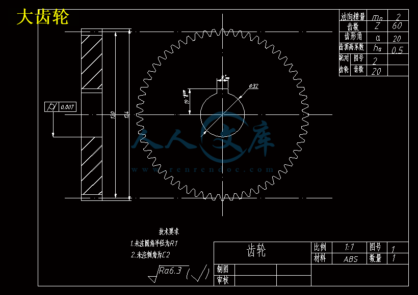
大齿轮.dwg
小齿轮.dwg
摇摆装置齿轮.dwg
摇摆装置齿轮盘.dwg
装配图.dwg
压缩包内文档预览:(预览前20页/共35页)
预览图 预览图 预览图 预览图 预览图 预览图 预览图 预览图 预览图 预览图 预览图 预览图 预览图 预览图 预览图 预览图 预览图 预览图 预览图 预览图
编号:10613715    类型:共享资源    大小:18.63MB    格式:RAR    上传时间:2018-09-02 上传人:俊****计 IP属地:江苏
50
积分
关 键 词:
乒乓球 发球 结构设计 三维 cad 图纸 以及 说明书 仿单
资源描述:

摘要


乒乓球是一项集速度、耐力、反应力和力量为一体的运动,同时也是考验技术和战术的运动。乒乓球运动不仅适合小孩也适合老人的运动,对身体素质要求不高。随着科技生活的不断发展,人们的生活水平不断的提高,人们追求也不断提高。为了使广大练习者能达到学习乒乓球技术和健身的效果,本文设计了一种方便且好控制的乒乓球发球器。

本文综述了普遍的乒乓球发球器的类型和优缺点。了解乒乓球发球的原理,设计一种以对转双摩擦轮的发球原理,能够发射上下旋球和不旋球;采用了丝杠与螺母的配合其工作的原理,设计出乒乓球发球器的升降装置。利用齿轮带动输球管上啮合的齿盘设计摇摆装置;采用六个收球槽的叶片轮输球。对乒乓球发球器的功能结构等设计分析。本文采用三维造型设计和功能设计相结合,利用SolidWorks软件绘制乒乓球发球器的零部件和总装三维图。用AutoCAD绘制工程图。

本文设计乒乓球发球器结构比较简单,体积适中,拆装比较简单,容易操控,老少皆宜,能发射不同角度、速度和旋转的球。

关键词:三维结构设计;功能结构设计;SolidWorks;AutoCAD。


Table Tennis Ball Machine Design


Abstract: 

Table tennis is a set of speed, endurance, reaction force and strength as one of the sport, but also a test of technical and tactical movement. Table tennis is not only suitable for the elderly is also suitable for the elderly children exercise, physical fitness do not ask. With the development of life science and technology, people's living standards improve, people pursue is also rising. In order to reach the majority of practitioners can learn tennis technique and fitness results, design a convenient and well-controlled device of Table Tennis Service. 

This article reviews the common tennis ball on the type and advantages and disadvantages of. Learn of Table Tennis Service principles designed to serve a dual friction wheel rotation principle, capable of firing up and down spin and not spin; Using the principle of the screw and nut with its work to design the lifting device of Table Tennis Service. The use of gear drive engaging losing teeth on the tube plate design rocking device. It uses six received the ball slot blade wheels lose. Design and Analysis of Table Tennis the function structure. In this paper, three-dimensional design and functional design combined with SolidWorks software to draw table tennis ball machine components and assembly three-dimensional map. Engineering Drawing with AutoCAD.

This design I of Table Tennis Service structure is relatively simple, modest volume, disassembly is simple, easy to control, young and old are easily capable of firing different angle, speed and rotation of the ball.


Key words: three-dimensional structure design; functional design; SolidWorks; AutoCAD.

目 次

摘要 I

Abstract: II


1  引言 5

1.1 论文选题的根据和研究意义 5

1.2 常见的乒乓球发球器的种类 5

1.3 设计的主要内容 7

1.4 小结 7

2  乒乓球发球器的要求和准则 8

2.1 乒乓球发球器过程 8

2.2 乒乓球发球器的要求 8

2.3 整体方案 8

2.4 乒乓球发球器整体参数 9

2.5 小结 9

3  乒乓球发球器传动设计 10

3.1 乒乓球发球器原理 10

3.2 乒乓球发球器的升降装置和摇摆装置的设计 11

3.3 乒乓球发球器的电机选择 12

3.4 输球装置的设计 14

3.5 传动部分的设计 14

3.6 储球箱和拨球装置的设计 19

3.7小结 20

4  乒乓球发球器部分零部件三维设计 21

4.1 乒乓球发球器箱体的设计 21

4.2 机头管道设计和摩擦轮的选择 21

4.3 电机造型 22

4.4 底座板设计 22

4.5 小结 23

5  乒乓球发球器的装配设计 24

5.1 重点部分零部件的装配设计 24

5.2 输球装置电机与叶片轮装配 24

5.3. 乒乓球发球器发射装置的装配设计 25

5.4 升降装置的装配 27

5.5 拨球装置和储球箱的装配 28

5.6 摇摆装置的装配 29

5.7 各大部分的装配 30

5.8 本章小结 31

6  乒乓球发球器的使用注意事项和保养 32

7  总结 33


致谢 34

参考文献 35


1  引言

1.1 论文选题的根据和研究意义

乒乓球运动是无国界的运动,在乒乓球这个运动中,发球的好坏决定着输赢的一半。发球在乒乓球运动的各个技术中是不受对手限制,能够体现出自己的个性、进攻性和想象力等。在乒乓球比赛中,高质量的发球不仅能够直接得分,还能为进攻创造有利条件,并使对手产生较大的心理压力。随着乒乓球运动的不断发展,发球的种类越来越多,发球的好坏成了一个选手能否成功的首要因素之一。到21世纪乒乓球运动已经越来越为人们喜爱,为了推动乒乓球运动更好的融入社会,其中在2002年10月1日,将乒乓球发球改为了“无遮挡发球”,国际乒联提高了乒乓球比赛的观赏性,使比赛回合增加,促使世界乒乓球运动更好的向前发展,以求最大限度地降低发球者给对方造成的直接威胁,利用无遮挡发球降低接发球者的难度。为快速适应新规则的发球技术,探索新的发球技术,寻求更科学、有效的发球训练方法,以保持我国乒乓球运动在世界上的领先地位。

本课题设计的一种多功能的乒乓球发球器,主要利用机电相结合,这种发球器可以将发球速度控制在10m/s到20m/s,发射多角度、多速度的线路球或组合球,为更多的业余的爱好者或专业选手提供更多的选择。大大缩短使用者的掌握规范全面的技术的训练时间。


内容简介:
本科学生毕业设计(论文)任 务 书系( 院 ): 机械与控制工程学院 课题名称: 乒乓球发球器的结构设计 专业(方向): 化机械设计制造及其自动 (机械装备设计与制造 ) 班 级:学生姓名:指导教师:下发日期:课题名称 乒乓球发球器的结构设计主要内容(包括设计参数)与要求本次设计的主要内容是一种乒乓球发球器设计,具体内容包括以下 5 部分:(1) 了解乒乓球发球器原理及要求。(2) 设计乒乓球发球器总体方案。(3) 进行整体的设计。(4) 对机械部分的设计、验算,给出零部件图和装配图。(5) 编写毕业设计(论文)说明书。工 作 进 程 及 工 作 量1-2 周:1.资料检索、查询、收集及设计分析。2. 写出开题报告 3000 字以上。3-4 周:实习完成系统总体方案构思及设计。5-6 周:查阅相关软件资料并初步掌握7-8 周:完成主要机构的设计9-10 周:完成机构的三维设计11-12 周:完成设计的其他部分13-14 周:1.书写说明书(10000 字以上,中、外文摘要、目录、正文、参考文献,形式完整) 。2.修改错误。3.完成所有设计成果4.教师审查,提出修改意见15 周:修改、检查打印论文,准备答辩16 周:答辩。注:学生于 5 月 11 前必须上交论文初稿的电子文档到指导老师处。应 遵 守 的 法 规1遵守学校相关规定2严格按计划(工作进程)进行毕业设计工作。毕业设计(论文)完成日期: 2015 年 5 月 31 日指 导 教 师 : (签字)教研室主任: (签字)本 科 毕 业 设 计 (论 文 )外文翻译(附外文原文)系 ( 院 ): 课 题 名 称 :乒乓球发球器的结构设计 专业(方向): 班 级: 学 生: 指 导 教 师 : 日 期 : 第 29 届中国控制会议论文集7 月 29 日至 31 日,2010 年,北京,中国基本姿势 5 自由度混合机械臂控制算法适合乒乓球机器人ZHENG Kuijing1, CUI Pei 1, MAO Haixia21.机械工程学院,燕山大学,秦皇岛,066004 中华人民共和国电子邮件:kjzheng2. E啊科学河北科技师范学院的学院,秦皇岛,邮编:066004摘要:发展和乒乓球机器人的组成进行了介绍。基于乒乓球,一种 3-RPUR+ RP5 自由度混合机械臂提出,它可以执行三个平移自由度和两个旋转自由度的运动特性。通过使用 DH 参数法和 XYZ 欧拉角,混合动力车机械臂的运动学逆溶液进行分析,球拍的姿势被方便地描述。姿态控制方程被推导,这可变换球拍构成在工作空间到关节空间的驱动轴的参数。通过 ADAMS 软件,将运动仿真被执行,从而有效地证明了理论分析。基本算法奠定了成功的 5 轴联动控制的乒乓球机器人的理论基础。关键词:乒乓球机器人,自由的五度,混合机械手臂和姿态的反解1 引言作为一个服务机器人,乒乓球机器人可用于不仅为专业运动员作为试马针对性的训练,而且在行使对业余运动员。因此,乒乓球机器人吸引了来自学术界和工业界国内外越来越多的关注。许多大学和公司都在打乒乓球的机器人了深入的研究,并开发了多种乒乓球的机器人在不同结构和类型的自 1980 年以来初步乒乓球机器人具有比服务多样化球的功力没有其他的话,机械臂进行开发反击即将到来的球。 1983 年,约翰比林斯利1从英国朴茨茅斯理工大学约占乒乓球机器人法规。罗素 L.Andersson 2,宫崎文雄3等开发的乒乓球机器人一个接一个。建昌元4从西安理工大学,德许5从北京自动化研究所和魏巍6浙江大学还研究了乒乓球的机器人。的详细介绍可以在参考进行检查7。乒乓球机器人由机械系统,视觉系统和控制系统。作为手眼协调系统,三个子系统必须彼此协调。机械系统,类似于人类的手臂,直接进行打乒乓球的功能。视觉系统,类似于人的眼睛,监视乒乓球运动,并预测其运动轨迹。控制系统,类似于人类的大脑,控制所述机器人臂以敏捷摆动球拍根据移动轨迹乒乓去的规划位置和方向,并实现了精确的命中。A 排序五自由度混合机械臂包括并行机制和串行机制提出,它可以执行三个平移自由度和两个旋转自由度。混合机械臂的运动学反解进行了深入分析。的位置和方向的控制方程推导。在前述的算法仿真,通过 ADAMS 软件的方式进行验证。该算法还规定,为人们控制机器人手臂的姿势的理论基础。2 方案乒乓球机器人基于 5 自由度混合机械臂柔性双眼视乒乓球机器人的方案示于图 1 的混合式机器人臂装置串行机制连接到并行平台。它包括三个 RPRU(回转-棱柱回转通用型) ,四肢和RP(回转-棱镜)肢。球拍安装在机器人臂的末端。在该并联机构中三个平移对和在串行机制两个旋转对被用作驱动轴达到 5 轴同步控制。球拍能够摆动到达需要的位置,方向和速度。两个 2 自由度摇篮头上面的机械臂安装和 CCD 照相机被安装在每个托架的头。两款相机都可以进行旋转 2 自由度,形成灵活的双眼视觉。图 1:乒乓球机器人计划乒乓球的机器人是一个手眼协调系统与快速的眼睛和灵巧的手。该机器人可以摆动它的球拍敏捷,灵活,精确打击乒乓球和避免现有的人类击球的正反手问题。3 说明 5 自由度混合机械臂乒乓球具有速度快,各种坠落点,广泛和强烈的旋转等特点。因此,机械臂必须满足顺序执行这些要求,以适合打回乒乓球。一方面,它必须是多自由度来实现的各种位置和方向和摆动球拍去的规划点。另一方面,它需要有足够的工作空间到盖体内部并在表外部更大的面积和回击各个到来乒乓球。此外,速度快,精度高,还需要快速,准确地回击了乒乓球。基于上述分析,一种 3- RPUR+ RP 5 自由度混合机械臂提出。如图 2 所示,混合机构由稳定的平台,移动平台,其与移动平台,旋转对和平移一对串联在移动平台和安装在端球拍连接稳定的平台四肢机器人手臂。其在特征在于:在稳定的平台和移动平台都具有相同的连接3 RPUR(旋转,平移万能旋转)驾驶的肢体。通过控制 P 对三个 RPUR 驱动四肢的位置和移动平台的取向的运动可以被改变以实现两维转动和一维平移。旋转一对 R 4 与移动台连接的,使周围的移动平台的中心轴的摆动杆 L4 转动。在摆杆 L4 平移对 P5 使得沿摆杆轴方向的球拍 P 数据搬移。a)机器人臂模型 b)该坐标机械臂系统图 2:3 RPUR+ RP5 自由度混合机械臂通用对和旋转对的轴的两个轴在一个点上相交的 3- RPUR 并联机构,其等于球体对,即 3-RPS 机构。 3-RPS+ BP 混合机械臂自由度可以计算通过使用Kutzbach Grubler 的公式如下:M =610 11-117 =5这样的3-RPS+ BP混合机器人手臂的自由度是5。该混合机械臂结合高刚性,速度快,惯性小,误差小,高负荷和简单的敏捷和串行机制,宽大的空间足够并联机构的结构。的惯性和累积误差被降低。的刚性提高。的运动精度和运动速度提高。的位置和取向以及动态属性的敏捷性被有效地提高。该混合机械臂能够进行球拍的运动计划更迅速,敏捷,准确地在不同的速度,落点,角度和各种未来乒乓球的条款。4. 混合机械臂的运动学逆解4.1转发和RP肢体位置分析反解用DH法8,该坐标系上的旋转对R4,平移对P5,哪些是在移动的平台上链接的乒乓球拍分别成立。如图2 b)的移动坐标系统B是基准坐标系中的0,坐标系4对应于R 4,坐标系5对应于P5的坐标系统P对应的乒乓球拍。表1示出了相应的D-H参数。 Q4和d5的是变量,A1,A2,d1和d3的是常数。90度A190A2,D1lB4,D3 l5P。LB4是坐标系统B和坐标系统P的原点的原点之间的距离。表 1:D-H RP 肢的参数根据表 1 中的参数,变换矩阵(_B P)的坐标系统P相对于坐标系统B的 T 被给出如下:在公式(1) ,S 是 sin,c 是 COS。从等式(1) ,相对于P的原点的位置,可以在B表示:等式(2)是反相肢体的位置的正解,所以逆溶液给出如下:4.23-RPS 肢体位置分析的反解如图 2,3-RPS 并联机构的移动平台是正三角形 S1S2S3。移动坐标系B是建立在移动平台上。产地 OB 位于动平台的几何中心。 Axis_XB 恰逢载体 OBS1。稳定的平台也是一个正三角形 R1R2R3。稳定的坐标系A是建立在稳定的平台。产地 OA 位于稳定的平台的几何中心。 Axis_XA 恰逢载体 OAR1。相对于三个旋转对 R1,R2 和 R3 的三个轴是相切的稳定的平台的外接圆。外接圆半径为 A R。的三个关节的 R1,R2 和 R3 可以在坐标系A中被表示为如下的位置:正三角形 S1S2S3 的外接圆的半径为 Rb。三关节 S1,S2 和 S3 的位置可以被表示在坐标系统B如下:然后变换B相对于A可以表示如下的矩阵:在公式(4) , OB 原产地在A的位置。表示旋转矩阵和(A,B,g)为B相对于A的取向的欧拉角。关节的 Si(1 ,2,3)的位置的坐标系A中可被表示为如下:然后,在A的驱动轴的长度矢量可以举出:从等式(6) ,所有的驱动轴的长度可以计算:在 3-RPS 并联机构三个约束方程给出9:.从等式(8) ,下面的方程可以给出:从方程(9) ,在移动平台的位置和取向的 6 个参数,以及是独立的。一个,并且可以通过上述三个约束方程来解决。然后将三个驱动轴的长度可以表示为如下:4.3 姿态混合机械臂的逆解从等式(1)和(4) ,P相对于A的变换矩阵给出如下:在公式(11) ,是相对于P的A原点 OP 的位置。它可以表示为如下:在欧拉角 表示的旋转矩阵为P相对于A。是P相对的欧拉角A的欧拉角。4.4 姿势 3-RPS+ RP 混合机械手臂的控制方程的球拍可以通过所描述的位置和方向表示的球拍中A的中央点的位置,并且表示相对于球拍的取向的方向角。通过使用方向余弦的 ZP之间以及在三个坐标中A轴分别描述。从变换方程,规划的参数所构成的球拍,移动平台和(D5,Q4) ,反相肢的 DH 参数的姿势的参数由等式(12)中描述的。通过使用等式(12) ,的位置和移动平台的取向的数据可以根据相对于球拍的位置和方向的输入数据来计算。然后,利用位置反式(10) ,该规划姿势在工作空间的球拍可以被翻译成大约在关节空间的旋转轴的驱动轴和角度的长度。机器人手臂的运动控制可以通过等式(13)的方式来实现。机器人臂可以被控制以摆动其火箭到达规划姿势很快以便回击未来球准确。5 仿真图 3:模拟的流程图3 RPUR+ RP5 自由度混合机械臂可以在 SolidWorks 中构建。然后,该实体模型是通过一种数据转换格式命名的 Parasolid 导入 ADAMS。现有在 SolidWorks 中装配和约束关系成为 unvalid 当他们在 ADAMS。因此,有必要定义约束模型中的所有部分。首先,成立了工作状态。然后定义运动副的约束,包括固定对,对平移和旋转对。运动关系可以通过运动副装载驱动运动构造,其中四对平移一转动对10-11。最后,仿真可以通过导入的驾驶数据来获得。的流程图被示出为图 3.是机器人手臂的结构参数如下:rA=300mm, rB=220mm, lB4=132m, l5P=40mm是在驱动轴的初始参数如下:l1=l2=l3=679.72mm, q4 =0 , d5=500mm机器人手臂的规划动作如下:(500,0,847,90,90,0)(0,400,1147,110,108.75,27.99 O)(-200,0,847,90,90,0)(0,-400,1147,70,71.253,27.99)(500,0,847,90,90,0)表 2:姿势火箭数据表 3:机器人手臂的驾驶数据图 4:混合机械臂的运动模拟图通过使用所构成的机器人手臂的控制方程,所述规划的位置和方向的数据(参照表 2)的火箭,可以计算以获取控制数据(参照表 3)然后,控制数据可以在每个驱动轴被装载在 ADMAS 软件。和火箭的运动轨迹可以生产。如图 4 的模拟结果一致的规划轨迹。6 结论3 RPUR+ RP5 自由度混合机械臂可以执行三个平移自由度和两个旋转自由度。通过使用XYZ 欧拉角表示了火箭的位置和取向,所述机器人的运动学逆溶液简明解决。关于火箭的姿态控制式成立。通过 ADAMS 软件,模拟执行,从而有效地证明了理论分析。基本算法将为 5 轴同步控制的乒乓球机器人的理论基础。参考1比林斯利 J.机器人乒乓C。在:实用计算。马萨诸塞州:麻省理工学院出版社,1983 年。2罗素 L.安德森。的机器人乒乓播放器:在实时控制实验。马萨诸塞州剑桥:麻省理工学院出版社,1987 年。3宫崎文雄弥雅志松和竹内正博。学习动态处理:乒乓球机器人控制一个球和集会有一个人,先进的机器人控制。施普林格,2006 年。4常健元。研究乒乓球机器人的手,杂志纺织科学与技术,2001,15(1)西北研究所:44-49。5郑涛张,许德和君宇智。研究和乒乓球机器人的最新发展。 4881-4886:第七届世界大会对智能控制与自动化,重庆,中国,2008 年提起诉讼。6袁辉张,魏巍和丹宇。基于实时图像卡尔曼跟踪算法。浙江大学,2009 年,43(9):1580 至 1584 年。7郑窥镜,裴翠。审查关于促进机器人乒乓球。机床和液压,2009 年,37(8):238-241。8游轮熊,鼎汉恩和刘苍。机器人技术。中国机械工业出版社,1993 年。9闫文丽,黄震。用奇异研究方法基于运动学及其应用实例。中国机械工程学报,2004,17(2):161-165。10曾李刚。关于 ADAMS 引进和例子。北京:国防工业出版社,2006。11广达朱佳顺世和广奇彩。 3-TPS 混联机床基于 ADAMS 运动学和动力学仿真。东北大学学报,2007,41(12):38-42。Proceedings of the 29th Chinese Control ConferenceJuly 29-31, 2010, Beijing, ChinaBasic Pose Control Algorithm of 5-DOF Hybrid Robotic Arm Suitable for Table Tennis RobotZHENG Kuijing1, CUI Pei 1, MAO Haixia21. Mechanical Engineering College, Yanshan University, Qinhuangdao, 066004, P.R.China E-mail: kjzheng2. E&A College of Hebei Normal University of Science & Technology, Qinhuangdao, 066004, P.R.ChinaAbstract: The development and the composition of table tennis robot are introduced. Based on the moving characteristic of table tennis, a sort of 3-RPUR+RP 5-DOF hybrid robotic arm is put forward, which can perform three translational DOFS and two rotational DOFS. By using D-H parameter method and XYZ Euler angle, the kinematic inverse solution of the hybrid robotic arm is analyzed and the pose of the racket is described conveniently. The pose control equation is deduced, which can transform the racket pose in working space into the parameters of the driving axis in joint space. By using ADAMS software, the motion simulation is performed so as to prove the theoretical analysis effectively. The basic algorithm lays the theoretical foundation for the successful 5-axis simultaneous control of the table tennis robot.Key Words: Table Tennis Robot, Five Degrees of Freedom, Hybrid Robotic Arm and Inverse Solution of Pose1 INTRODUCTIONAs a service robot, table tennis robot can be used not only in pertinent training for professional athletes as a trial horse, but also in exercising for amateur athletes. Therefore table tennis robot attracts increasing concern from academic and industrial community home and abroad. Many universities and companies have researched deeply in table tennis robot and developed a variety of table tennis robots in different structure and type since 1980. The initial table tennis robots had no other than the skill of serving diverse balls, then the robotic arm were developed to hit back the coming balls. In 1983, John Billingsley1 from Portsmouth Polytechnic University of Britain constituted regulations about table tennis robots. Russel L.Andersson2, Fumio Miyazaki3 and so on developed table tennis robots one by one. Jianchang Yuan4 from Xian Polytechnic University, De Xu5 from Beijing Research Institute of Automation and Wei Wei6 from Zhejiang University have also researched on table tennis robot. The detailed presentation can be checked in reference 7.Table tennis robot consists of mechanical system, vision system and control system. As a hand-eye coordinating system, the three subsystems must coordinate with each other. Mechanical system, similar to human arm, performs the function of hitting table tennis directly. Vision system, similar to human eye, monitors the movement of the table tennis and predicts its moving track. Control system, similar to human brain, controls the robotic arm to swing the racket agilely according to the moving track of the table tennis to get to the planning position and orientation and realize the accurate hit.A sort of 5-DOF hybrid robotic arm including parallel mechanism and serial mechanism is put forward, which can perform three translational DOFS and two rotational DOFS. The kinematic inverse solution of the hybrid robotic arm is analyzed deeply. The control equations of position and orientation are deduced. The forenamed algorithm is simulated and verified by means of ADAMS software. The algorithm also lays the theoretical foundation for people to control the pose of the robotic arm.2 SCHEME of TABLE TENNIS ROBOTThe scheme of table tennis robot based on a 5-DOF hybrid robotic arm with flexible binocular vision is shown in Figure 1. The hybrid robotic arm means connecting the serial mechanism onto the parallel platform. It includes three RPRU(Revolute-Prismatic-Revolute-Universal) limbs and a RP(Revolute-Prismatic) limb. The racket is installed at the end of the robotic arm. Three translational pairs in the parallel mechanism and two rotational pairs in the serial mechanism are used as driving axes to achieve 5-axis simultaneous control. The racket can be swung to get to the required position, orientation and velocity. Two 2-DOF cradle heads are installed eudipleurally above the robotic arm and a CCD camera is installed in each cradle head. Each camera can perform 2 rotational DOFS to form agile binocular vision.Fig.1: Scheme of table tennis robotThe table tennis robot is a hand-eye coordinating system with quick of eye and deft of hand. The robot can swing its racket agilely and flexibly to hit table tennis precisely and avoid the forehand and backhand problems existing in human hitting.3 DESCRIPTION of THE 5-DOF HYBRID ROBOTIC ARMThe table tennis has the characteristics of fast speed, various falling points, wide range and strong spin and so on. Therefore, the robotic arm must satisfy these requirements in order to be suitable for hitting back table tennis. On the one hand, it is required to be multi-degrees of freedom to realize the various position and orientation and swing the racket to get to the planning point. On the other hand, it is required to have adequate work space to cover more area inside and outside the table and hit back the various coming table tennis. In addition, fast speed and high precision are also required to hit back the table tennis quickly and accurately.Based on the above analysis, a sort of 3-RPUR+RP 5-DOF hybrid robotic arm is put forward. As shown in Figure 2, the hybrid mechanism consists of the stable platform, the moving platform, the limbs which connect the stable platform with the moving platform, the rotational pair and translational pair in series with the moving platform and the racket installed at the end of robotic arm. Its characteristic lies in: the stable platform and the moving platform are connected with the samethree RPUR (Rotational-Translational-Universal-Rotational) driving limbs. By controlling the motion of P pair of the three RPUR driving limbs, the position and orientation of the moving platform can be changed to realize two-dimension rotation and one-dimension translation. The rotational pair R4 linked with the moving platform makes the swing rod L4 rotate around the central axis of the moving platform. The translational pair P5 on the swing rod L4 makes the racket P move along axial direction of the swing rod.a) robotic arm model b) the coordinate systems of the robotic armFig.2: 3-RPUR+RP 5-DOF hybrid robotic armThe two axes of the Universal pair and the axis of the Rotational pair intersect at one point in the 3-RPUR parallel mechanism, which is equal to a sphere pair, namely 3-RPS mechanism. The degrees of freedom of the 3-RPS+RP hybrid robotic arm can be calculated by using the following equation of Kutzbach Grubler:M =610 11-117 =5So the degrees of freedom of the 3-RPS+RP hybrid robotic arm are 5.The hybrid robotic arm combines high rigidity, fast speed, small inertia, small error, high load and simple structure of parallel mechanism with agility and large work space of serial mechanism sufficiently. The inertia and the accumulative error are reduced. The rigidity is enhanced. The kinematic accuracy and the kinematic velocity are improved. The agility of the position and orientation and dynamic properties are improved efficiently. The hybrid robotic arm is able to carry out the planning movement of the racket more quickly, agilely and accurately in terms of different speed, falling points, angles and variety of the coming table tennis.4 KINEMATIC INVERSE SOLUTION of THE HYBRID ROBOTIC ARM4.1 Forward and inverse solution of position analysis of RP limbBy using D-H method8, the coordinate systems are established respectively on rotational pair R4, translational pair P5 and the table tennis racket which are linked in the moving platform. As shown in Figure 2 b): the moving coordinate system B is the basic coordinate system 0, the coordinate system 4 corresponds to R4 , the coordinate system 5 corresponds to P5, the coordinate system P corresponds to table tennis racket. Table 1 shows the corresponding D-H parameters. q4 and d5 are variables, a1 ,a2 , d1 and d3 are constants. 90o a1 , 90o a2 , d1 lB4 , d3 l5P . lB4 is the distance between the origin of the coordinate system B and the origin of the coordinate system P.Tab.1: D-H parameters of RP limbAccording to the parameters in Table 1, the transform matrix of the coordinate system P relative to the coordinate system B is given as follows:In equation (1), s is sin and c is cos.From equation (1), the position with respect to the origin of P can be represented in B:Equation (2) is the forward solution of the position of RP limb, so the inverse solution is given as follows:4.2 Inverse solution of the position analysis of 3-RPS limbAs shown in Figure 2, the moving platform of 3-RPS parallel mechanism is a regular triangle S1S2S3 . The moving coordinate system B is established on the moving platform. Origin OB is located in the geometric centre of the moving platform. Axis_XB coincides with vector OBS1 . The stable platform is also a regular triangle R1R2R3. The stable coordinate system A is established on the stable platform. Origin OA is located in the geometric centre of the stable platform. Axis_XA coincides with vector OAR1 .The three axes relative to the three rotational pairs R1,R2 and R3 are tangent to the circumcircle of the stable platform. The radius of the circumcircle is A r . The position of the three joints R1, R2 and R3 can be represented in the coordinate system A as follows:The radius of the circumcircle of the regular triangle S1S2S3 is rB . The position of the three joints S1, S2 and S3 can be represented in coordinate system B as follows:Then the transform matrix of B relative to A can be represented as follows:In equation (4), the position of origin OB in A.represents the rotation matrix and (a,b ,g ) is Euler angle of orientation of B relative to A.The position of joints Si (i 1, 2,3) in the coordinate system A can be represented as follows:Then, the length vector of the driving axes in A can be given:From equation (6), the length of all driving axes can be calculated:Three constraint equations in 3-RPS parallel mechanism are given9:From equation (8), the following equation can be given:From equation (9), in the six parameters of the position and orientation of the moving platform, , and are independent. a , and can be solved by the three constraint equations above. Then the length of the three driving axes can be represented as follows:4.3 Pose inverse solution of hybrid robotic armFrom equation (1) and (4), the transform matrix of P relative to A is given as follows:In equation (11), is the position with respect to the origin OP of P in A. It can be represented as follows:is the rotation matrix represented in Euler angle and is the Euler angle of P relative to A.is the Euler angle of P relative to A.4.4 Pose control equation of 3-RPS+RP hybrid robotic armThe position and orientation of the racket can be described by represents the position of the central point of the racket in A and represents the direction angle with respect to the orientation of the racket. is described by using the direction cosine between axis_Z of P and the three coordinate axes in A respectively.The transform equations from , parameters of the planning pose of the racket to , parameters of the pose of the moving platform and (d5,q4 ) , D-H parameters of RP limb are described by equation (12).By using equation (12), the data of position and orientation of the moving platform can be calculated according to the input data with respect to the position and orientation of the racket. Then, making use of inverse position equation (10), the planning pose of the racket in work space can be translated into lengths of the driving axes and the angles about the rotation axes in joint space. The motion control of the robotic arm can be implemented by means of equation (13). The robotic arm can be controlled to swing its rocket to get to the planning pose quickly so as to hit back the coming ball accurately.5 SIMULATIONFig.3: The flow chart of simulationThe 3-RPUR+RP 5-DOF hybrid robotic arm can be constructed in Solidworks. Then the entity model is imported into ADAMS through a sort of data conversion format named parasolid. The assemblage and constraint relationship existing in Solidworks become unvalid when they are in ADAMS. Therefore, it is necessary to define constraints for all the parts in the model. First, set up the working condition. Then define kinematic pairs constraints, including fixed pair, translat
温馨提示:
1: 本站所有资源如无特殊说明,都需要本地电脑安装OFFICE2007和PDF阅读器。图纸软件为CAD,CAXA,PROE,UG,SolidWorks等.压缩文件请下载最新的WinRAR软件解压。
2: 本站的文档不包含任何第三方提供的附件图纸等,如果需要附件,请联系上传者。文件的所有权益归上传用户所有。
3.本站RAR压缩包中若带图纸,网页内容里面会有图纸预览,若没有图纸预览就没有图纸。
4. 未经权益所有人同意不得将文件中的内容挪作商业或盈利用途。
5. 人人文库网仅提供信息存储空间,仅对用户上传内容的表现方式做保护处理,对用户上传分享的文档内容本身不做任何修改或编辑,并不能对任何下载内容负责。
6. 下载文件中如有侵权或不适当内容,请与我们联系,我们立即纠正。
7. 本站不保证下载资源的准确性、安全性和完整性, 同时也不承担用户因使用这些下载资源对自己和他人造成任何形式的伤害或损失。
提示  人人文库网所有资源均是用户自行上传分享,仅供网友学习交流,未经上传用户书面授权,请勿作他用。
关于本文
本文标题:乒乓球发球器的结构设计(含三维)【6张CAD图纸和说明书】
链接地址:https://www.renrendoc.com/p-10613715.html

官方联系方式

2:不支持迅雷下载,请使用浏览器下载   
3:不支持QQ浏览器下载,请用其他浏览器   
4:下载后的文档和图纸-无水印   
5:文档经过压缩,下载后原文更清晰   
关于我们 - 网站声明 - 网站地图 - 资源地图 - 友情链接 - 网站客服 - 联系我们

网站客服QQ:2881952447     

copyright@ 2020-2024  renrendoc.com 人人文库版权所有   联系电话:400-852-1180

备案号:蜀ICP备2022000484号-2       经营许可证: 川B2-20220663       公网安备川公网安备: 51019002004831号

本站为文档C2C交易模式,即用户上传的文档直接被用户下载,本站只是中间服务平台,本站所有文档下载所得的收益归上传人(含作者)所有。人人文库网仅提供信息存储空间,仅对用户上传内容的表现方式做保护处理,对上载内容本身不做任何修改或编辑。若文档所含内容侵犯了您的版权或隐私,请立即通知人人文库网,我们立即给予删除!