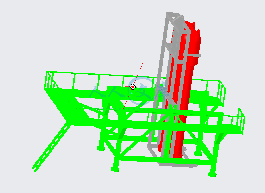
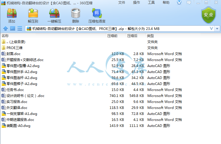
机械结构-自动翻转台的设计【含CAD图纸、PROE三维】
收藏
资源目录

压缩包内文档预览:(预览前20页/共21页)
编号:13196851
类型:共享资源
大小:9.24MB
格式:ZIP
上传时间:2019-01-12
上传人:机****料
认证信息
个人认证
高**(实名认证)
河南
IP属地:河南
50
积分
- 关 键 词:
-
含CAD图纸、PROE三维
机械
结构
自动
转台
设计
cad
图纸
proe
三维
- 资源描述:
-


- 内容简介:
-
毕业设计(外文翻译)Virtual engineering: an integrated approach to agile manufacturing machinery design and controlP.R. Moore,J.Pu, H.C. Ng, C.B. Wong , S.K. Chong ,X. Chen , J. Adolfsson , P. Olofsgard , J.-O. LundgrenAbstractA virtual manufacturing approach for designing, programming, testing, verifying and deploying control systems for agile modular manufacturing machinery are proposed in this paper. It introduces the concepts, operations, mechanisms and implementation techniques for integrating simulation environments and distributed control system environments so that the control logic programs that have been programmed and veried in the virtual environment can be seamlessly transferred to the distributed control system environment for controlling the real devices. The approach looks to exploit simulation in a much wider range of applications with great advantages in the design and development of manufacturing machine systems. In particular, it facilitates the verication of the runtime support applications using the simulation model before they are applied to the real system. Mechanisms that allow runtime data to be collected during operation of the real machinery to calibrate the simulation models are also proposed. The system implemented delivers a powerful set of software tools for realising agile modular manufacturing systems. 1. IntroductionAgility is widely recognised as one of the most important attributes for manufacturing systems to satisfy the needs of competitive global markets, which are resulting in the need to produce high quality products at low cost with shortening product lives and ever increasing demands for differentiation through customisation1. By agility, it can mean that manufacturing systems have to respond to production changes both in volume and variety rapidly, effectively and reliably with low cost. Virtual manufacturing (VM) and virtual engineering have been identied as one of the enabling technologies of agile manufacturing and its related activities 2,3.One denition of virtual manufacturing is to carry out manufacturing activities with a simulation model of the actual setup, which may or may not exist. It holds all the information relating to the process, the process control and management and product specic data. It is also possible to have part of the manufacturing plant be real and the other part virtual 4. From such a denition, it can be inferred that integration of simulation models with process control and management data and possibly with the real system itself is an essential ingredient within such an approach. In the manufacturing sector, simulation packages with three-dimensional modelling and animation capabilities (referred to as 3-D simulation hereafter) are progressively gaining favour. The visualisation capability provided by 3-D simulation packages not only provides much richer, closer-to-reality information for users, but also enables new application domains to be addressed such as rapid prototyping of machine systems. One example of 3-D simulation is computer aided robotic (CAR)systems 5, which are often utilised for the design and programming of industrialrobot based workcells. Such systems provide facilities for evaluating different cell congurations and layouts by allowing the users to choose diifferent robot models from a model library. Moreover, the same environment can be used for off-line programming robots through code generation, thereby shortening system development time, according to experience gained in the European automotive industry (e.g.Volvo, SAAB, etc.), where continuous 3-D simulation tools are used extensively to prepare programs for robot workcells. It should be recognised that the substantial cost of such software packages and the considerable expertise required in building useful models, requires a considered commitment to the use of such tools. However,the most appealing attraction for manufacturers to use CAR systems is that programming and testing stage can commence very early once an order is received,enabling reduced lead-times without disrupting production systems on the shop oor. Such orders may arise from the introduction of new equipment, new product types, and/or changes in production volume, etc. In other words, simulation plays a signicant role in bringing systems into operation more rapidly and more reliably because more testing and verication can be done earlier in the life cycle in a safeenvironment.Automatic code generation is highly desirable by translating simulation programs to machine control code. However, such a feature is only generally available for conventional and standard machinery such as CNC machines and industrial robots.A general solution for designing and off-line programming special purpose manufacturing machinery is not currently available. Such machine systems are typically built from customisable modular automation equipment that is congured from modular components such as sensors, actuators and motion controllers, etc., which are supplied by multiple vendors and typically operate within heterogeneous platforms. In most cases, when graphical simulation has been applied during the design process, this implies that control engineers have to re-implement the control logic described in a simulation model when developing the software for the real control system. Mis-interpretation and sub-optimal implementation can be the result of such a discontinuity in the process 6. Such shortfalls can also lengthen delivery times and diminish the intended benets from applying simulation.This paper proposes a highly integrated approach to machine system development, whereby design, simulation and distributed control are facilitated. In particular, it focuses on the concepts and implementation techniques for integrating simulation environments and distributed control system environments so that control logic programs that have been designed, tested and veried in the simulation environment can be seamlessly transferred to the distributed control system environment for operations of real devices. The proposed approach looks to exploit simulation in a much wider range of applications with signicant benets in the design and development of manufacturing machine systems. To this end a number of integration mechanisms are facilitated in supporting processes in a typical machine design and development life cycle. These include: (i) exchanging the control requirement/design information between simulation and the control system design environment; (ii) control logic program transfer from simulation to the distributed control of real devices; (iii) runtime support application verication using simulation; and (iv) collection of runtime data to calibrate simulation models. Such an integrated approach has been successfully applied to the design and development of real industrial demonstrator cell for assembly of cylinder-head valves, within an installation at Euromation (a Volvo group company), Sweden.The research described in this paper is based on the outcome of a major European Commission funded project VIR-ENG. A brief introduction to this research project is given in the following section. The paper is organised as follows, Sections 3 and 4 introduce the key elements of the proposed approach; integration mechanisms and their implementation are addressed in Section 5; Section 6 briey summaries successful application examples of the approach.2. VIR-ENGThe concepts and corresponding tools addressing machine systems design presented in this paper were rst devised and implemented in the European Commission Framework IV ESPRIT research project Integrated Design, Simulation and Distributed Control of Agile Modular Manufacturing Machine Systems (VIR-ENG),which concluded successfully in June 2001. The project objective was to develop highly integrated design, simulation and distributed control environments for building agile modular manufacturing machine systems which offer the inherent capacity to allow rapid response to product model changes and feature variants 7. Fig. 1 illustrates the organisation of the project and the associated work packages and their inter-relationships. Among these work-packages, the modular machine design environment (MMDE) and the distributed control system environment (DCSE) are the two major environments that support different facets in the machine system life cycle. Although VIR-ENG has identied two distinctive environments, the end-user will not necessarily see two separate environments at all and will employ both as a seamless whole.2.1. VIR-ENG manufacturing machine system modelIn VIR-ENG, a four-layer manufacturing machine system model is devised to serve as a reference model for both MMDE and DCSE to ensure integrity in analysis, design and implementation in building machines and their associated control systems. The four layers in the model are illustrated in Fig. 2. 2.2. MMDEthe design and simulation environmentThe MMDE supports the design/virtual engineering of the physical elements and control logic of component-based manufacturing machine systems. From the viewpoint of end users, MMDE consists of two major environments: (i) the design/simulation environment and (ii) the programming environment. These environments together with a number of specialist tools, constitute the MMDE. The simulation environment in MMDE is where virtual models of the machine system are produced,tested and evaluated. The programming environment of MMDE provides the programming interface that allows users to dene the control logic for driving the virtual machine system. One of the unique features introduced by VIR-ENG, the control logic to drive the simulation entities is described using programming languages dened in IEC1131 Part 3 (IEC1131-3) 8. Further description of MMDE can be found in Refs. 9,10.CSDE provides the tool-set to comprehensively support the activities in the design and development of control systems. These include tools for users, particularly electrical and control engineers to: (i) design and specify the control architecture using standard UML notation 11; (ii) generate the machine/machine system control components based on the control logic that are dened and veried in MMDE; (iii) mechanisms for mapping the interfaces of control components to corresponding eld devices; and (iv) recongure or modify existing control systems. CSDE tools can be further structured into two major tool-sets; namely, (i) control architecture design environment (CADE), and (ii) control system programming environment (CSPE). DRE provides a framework and associated runtime support component library for creating network-enabled runtime support applications for machine systems. DRE-developed runtime support are featured with distributed human machine interfaces (HMI) with embedded functionality including conguration and monitoring, alarm handling, diagnostics and maintenance for supporting the operation of the manufacturing machine system and associated production facilities.All VIR-ENG environments are designed and implemented to support and encourage reusability of machine components (hardware/software). In particular, the underlying information infrastructure (IIS) delivers a component library, which serves as a structured repository for components designed in VIR-ENG environments. The IIS also provides a component manager for users to manage the components in the library. Furthermore, the CDE within the DCSE denes theunderlying reference model for supporting the activities in CSDE and DRE.Since VIR-ENG has introduced a number of important concepts addressing a wide range of machine system developments, a detailed review of the project and individual environments is beyond the scope of this paper. The paper goes on to focus on the integration between MMDE, CSDE and DRE, which provides a reference for integrating simulation and distributed control design and operating environments. It is important to point out that, even though the concepts andimplementation techniques presented were rst devised and applied in VIR-ENG, the authors believe that they can be more generally applied in integrating simulation environments and distributed control environments without necessarily conforming to the overall specic architecture described here. Nevertheless, for the sake of brevity and clarity, the acronyms adopted within VIR-ENG will be used throughout the paper. Conceptually, the readers may generally relate MMDE to the design and simulation environment that produces the simulation model of the machine system; CSDE to the design environment that generates the control software components for real devices; DRE to the design environment that produces the runtime support applications for machine systems.3. Elements for integration in machine system designFig. 3 illustrates the key elements in each environment and the process associated with integration of simulation and distributed control. Each element of the approach is described in this section before considering the integration process in Section 4.3.1. Simulation modelsAs the key output of MMDE, simulation models refer to the 3-D graphical simulation models that encapsulate information such as: (i) list of machine components and their CAD models; (ii) machine layout; (iii) kinematics properties (e.g.maximum allowable velocity); (iv) kinematics relationships; (v) application task logic (e.g. sequence, timing and synchronisation), etc.3.2. Control architecture specicationsControl architecture specications are the major output of the CSDE, which contain important information that must be referenced by all three environments for the remaining phases of the machine design and development process. Such specications, represented using UML-based diagrams and data tables, specify the following information: A list of control components, and their inter-relationshipsthis is the result of decomposing the system using methodologies based on task decomposition and a components, responsibilities and collaborations (CRC) method. Specications of the control component interfaces. These provide detailed information about the types and data semantics for each interface item of the control components. Specications of the control component services, which dene the required functionality. Specications for exception handling.The control specication forms the basis for developing the control logic programs in the MMDE to drive the simulation model. The dened specication also acts as a contractual agreement covering DRE requirements, which allows the runtime support/HMI developed in the DRE to be veried using the simulation model developed in MMDE. In summary, the control architecture specication is the core mechanism for integration of MMDE, CSDE and DRE.3.3. Control logic programsControl logic programs refer to the programs that specify the behaviour of individual machine components and their interactions. As a unique feature of the proposed solution, control logic for the virtual machines is described using IEC1131-3 programs rather than any native simulation language. Therefore, control logic programs exist in the form of program organisation units (POUs) dened in IEC1131-3, which may include programming constructs like function blocks and functions that support the development of well-structured programs and reuse of code. In order to facilitate the use of the same control logic programs to drive both the virtual machines and the real machines, three concepts are introduced, namely:(i) Virtual I/OCommunication between the control logic programs and the simulation is accomplished by exchanging data synchronously through a shared data block. In order to facilitate the seamless program transfer, the data to be exchanged (e.g. control signals and virtual device status) should resemble the I/O of the real system. The data block and its corresponding mechanism is thus termed virtual I/O. Other simulation-specic data such as the simulation clock time is also updated to the virtual I/O when the simulation is executing.(ii) Virtual component controllersThese are a set of generic software units that control the objects in the simulation which are developed using the native simulation languages. Having close association with virtual I/O, they are responsible for reading data from the shared data block and then generate the corresponding state change and graphical update. They also update the virtual I/O with the current status of the simulated machines.(iii) Motion function blocks (FBs)A list of user-dened IEC1131-3 FBs have been dened for representing the motions required by machine designers. These blocks possess the same meaning across both MMDE and CSDE. The effect of such blocks produced on the virtual model should be reproduced in the real control system designed in CSDE. However, contrary to other POUs, the actual implementations of the same block within the two environments are different,only the interfaces of the motion FBs are agreed across the environments. While the FB in MMDE contains the code to drive the virtual actuators, the same block in the CSDE encapsulates the code to generate the motion of the real device. Such a concept can also be applied generally to hide complexity behind interfaces to control any complex machinery. For example, two FBs are designed for controlling the AGV in the VIR-ENG demonstrator (see Section 6).In ideal cases, the same control logic programs developed to drive the virtual models can be transferred seamlessly to drive the real machines/devices with only minimal modication to re-map the interfaces from virtual I/O to real I/O. Nevertheless, it can be appreciated that in practice not all physical aspects can be considered in the virtual environment. Certain additional information may be needed when creating the control logic components for real machine systems. These could include: Hardware-specic initialisation: Most control devices require certain initialisation routines to be executed before operation. Such initialisation logic has not usually considered in the simulation environment and therefore needs to be specied in the CSDE. Exception handling: Some exceptions like sensor failure can be injected into the simulation model in order to test the control logic in handling such errors. Nevertheless, there exist some types of failure mode (e.g. timing related) that are largely impractical to test in the virtual environment. Extra exception handling logic has to be added to contend with these issues.It should be emphasised that such modications involve only supplementary code and do not invalidate the original logic generated in the virtual environment. It should also be appreciated that much of the exception handling logic can be generated and validated in the virtual environment.3.4. Runtime support and runtime dataAs mentioned earlier, DRE-developed runtime support features a distributed HMI with embedded functionality such as conguration and monitoring, alarm handling, diagnostics and maintenance, for supporting production related activities. Runtime data refers to data that is collected by the monitoring and logging functions of the runtime support from the real machine system in operation. Depending on the runtime support design, this data might include raw data from the machinery (e.g. analogue sensor readings) and/or high-level production data/information.4. Processes within the integrated approachWith reference to Fig. 3, the integration process typically starts by transferring the simulation models, which describe the mechanical design/layout, kinematics properties, kinematics relationships and application task logic to the CSDE as the blueprint for the control system design process. In return, the control architecture specications are transferred back to the MMDE and DRE for the development work in subsequent stages. With reference to the control components list produced from the control architecture specication, the simulation model in MMDE will be modied to include the virtual I/O information. Such a model plays an important role for the seamless integration between MMDE and DCSE in the subsequent control system development. Programming, testing and verication of the control logic programs against the modied simulation models is carried out using the tools provided by MMDE. Veried control logic programs are then transferred to CSDE, where the transformation into control logic components that control real hardware devices will take place. This step involves a number of CSDE-internal activities including interface binding, component generation and component deployment. Toolsimplemented that support these activities are described in Section 5.One of the unique features offered by this integrated approach is the capability to verify the runtime support using the simulation models. In this way the runtime support can be designed and rened before it is actually applied to the real machine system, which conventionally is a task that is usually delayed until the real machine system is commissioned. The veried runtime support application facilitates commissioning with a higher degree of condence when connecting to the real machines through the control components generated in CSDE. Furthermore, it can also signicantly reduce the time to deploy the machine or machine systems by facilitating concurrent development of the run-time support with the aid of the simulation model. The veried runtime support applications, together with the simulation models can also be used to provide a safe environment that can be used for training of machine operators and shop oor personnel enabling them to acquire suffcient knowledge to work with the real machines in a safe and effcient manner.Despite the fact that experienced designers can closely estimate the runtime performance of machine systems they are designing, it is almost impossible for them to obtain accurate operating data during the design and simulation stage for the following reasons: Certain data and/or properties of the machines are not possible to obtain by calculation or from the 3-D simulation unless a complex dynamic model of the mechanical components and their interactions have been built and integrated into the simulation model. Even the most sophisticated model will always contain some inaccuracies and approximations of the nal system. Most modern machine systems are designed to allow operators to adjust or alter the variables on the machines. Changes in such variables imply tuning the runtime performance of the machine, which is subjective and based on the operators experience. In other words, the precise operating data of the machine can only be obtained from running the real machine. The trend is towards building machine systems from known proven modules aggregated in customised congurations. However, even though the performance of individual modules will be known, the effects of interactions with other modules are diffcult to determine precisely.Therefore, to calibrate the simulation model using data collected by the runtime support is an essential mechanism to produce simulation models with higher delity. The calibrated simulation model can be used to investigate further improvements to the current system and furthermore it can be used in future design projects thus facilitating re-use and reconguration of the same machine components.Unlike a classical waterfall process in which the output in each step in the design process must be completed before the next step, the machine system design and development life cycle depicted in Fig. 3 advocates an incremental and iterative process with concurrent phases. The whole essence of the design paradigm of integrating the distributed control development environments with design and simulation is so that models can be built, changed or rened rapidly utilising concurrent processes.5. Mechanisms for integration and their implementationThis section describes the integration mechanisms used within the VIR-ENG machine system design tool-set.Fig. 4 illustrates the range of tools utilised within the system and their associated integration mechanism. Each environment was implemented by integrating a range of the best available commercial software tools together with in-house developed extensions and/or interface modules essential to the VIR-ENG approach, which are represented as dialog-box-like symbols in the gure. MMDE is developed by integrating the continuous simulation package IGRIP and the discrete event simulation package Quest from Delmia 12,13 with the ISaGRAF PRO IEC1131-3 programming environment from AlterSys International 14. CSDE is implemented by extending the ISaGRAF PRO toolkit, together with a number of customised tools. Inother words, ISaGRAF PRO is the common programming environment shared by both MMDE and CSDE. They also share a common library of motion FBs that have been described in Section 3.3. DRE is implemented by extending Microsoft Visual Basic 6.0 together with a library of ActiveX components for industrial automation systems. The data connection module of DRE was developed using ToolWorX from ICONICS 15. The selected software packages and toolkits were chosen because of their functionality and extendibility. To enhance the openness of the proposed solution as illustrated in Fig. 4, the current implementation is characterised by extensive use of the de-facto industrial standard OLE for process control (OPC) dened by the OPC Foundation 16.In MMDE, the IEC1131-3 control logic programs developed using ISaGRAF are compiled and downloaded to the ISaGRAF target. Such a target acts as the control logic execution program that drives the simulation. Communication between the ISaGRAF target and the simulation software is established through a virtual I/O module, which enables synchronised data sharing with other applications. Simulation entities respond to the control signal from the ISaGRAF target and produce the corresponding state change and graphical update. Their behaviours are determined by the virtual controller components developed using the native programming languages of the simulation software. Congurations of the virtual I/O module and virtual controller components are supported by the VEMacro module, which is a collection of extended functions developed to sit above the simulation packages. The data connection between the DRE-developed runtime support and the simulation models is established using the OPC mechanism, via the ISaGRAF OPC server that wraps the control logic programs. Through such a mechanism, the runtime support under test is logically connected to the same set of data items exposed by the real machine system in subsequent stages.In addition to the ISaGRAF programming environment, CSDE is composed of three proprietary software tools:(i) CADEprovides the graphical and tabular editor for electrical/control engineers to specify and generate the control architecture specication.(ii) VCon (VE COM congure)supports browsing and conguration of the OPC servers on the target platform in local and remote computers connected in the network. It also facilitates data item binding between control components.(iii) CBuilder (component builder)facilitates conversion of the IEC1131-3 control logic programs into VIR-ENG conformant control components.Because of the client/server model dened by the OPC standard, a single control component is realised as an executable application that acts as an OPC client and server simultaneously. As an OPC client, it manipulates the data items of the target platform OPC servers to control the physical devices. As an OPC server, it exposes its OPC interfaces for other control components and/or applications (e.g. Runtime support). From a programmers perspective, CBuilder supports the conversion of the ISaGRAF programs that constitute a single control component into C+ code. The C+ code is then compiled into control components in the form of an OPC-compliant executable application.To further enhance the exibility and openness of the proposed approach, ongoing development has adapted the MMDE virtual I/O module to comply with OPC communication capability so that a fully OPC-conformant solution shown in Fig. 5 can be achieved.6. Application examplesThe integrated tool-set described has been applied successfully to the design and implementation of the VIR-ENG demonstrator cell. The demonstrator was conceived as an exemplar for an agile modular manufacturing machine system for the assembly of cylinder-head valves for several engine variants. The demonstrator was congured from a modular assembly station, a large-scale gantry-loader connected by a network of modular conveyors and an AGV system. The demonstrator cell is operational in Euromation, a Volvo Group company, in Sweden.Fig. 6 displays a screen shot of the complete simulation model of the demonstrator cell. Simulation models have been built for each element of the cell includingthe complex assembly operations. Fig. 7 depicts a screen capture showing the assembly station model in conjunction with the IEC1131-3 programming environment.Controlling the operations of individual machines and their interactions involve both complex I/O events and precision motion control. During development of the control system for the workcell, each phase of the dened approach has been undertaken, from conceptual design of the workcell, to nal deployment of the control system and the graphical runtime support. In particular, the approach of programming and testing the IEC1131-3 programs for controlling the assembly station, conveyor systems and the AGV were undertaken using the tool-set provided by MMDE. The programs were then transferred to CSDE for conversion into control components that control the physical workcell. The control logic programs were seamlessly transferred without modication. Certain additions, mainly hardwarespecic initialisation functions, were necessary when building the control components for certain stations. One of the most important benets of the approach was that all control logic programming and full verication was possible before the machines were available. This greatly reduces risks to the machines and importantly allows concurrent development of both the control system and the mechanical system.Furthermore, the full runtime support system for the whole workcell was designed and tested very early in the development cycle using simulation models before it was connected and tested with the real devices. As an illustrative example, the screen snapshot in Fig. 8 shows the verication of a partially completed HMI designed for the conveyor system used in the demonstrator cell. Based on values read from the virtual I/O, the icons on the HMI show the states of the sensors and actuators utilised in the conveyor system. The conveyor system control logic was designed to support two modes of operation, namely automatic and manual modes. In automatic mode, all conveyor sections are controlled by programmed logic that has been veried earlier. Under this mode the HMI icons are mainly used for monitoring purposes. When switched to manual mode the operator can use the icons on the HMI to directly control the actuators in the conveyor sections. Verication of every icon on the HMI in both modes was undertaken without a need for the real machines. Similar processes were performed for the HMI for the other stations including the assembly station.Another unique aspect of the VIR-ENG approach is that data collected from operation of the real machines can be encapsulated within the simulation models in a calibration process to improve their accuracy. Application experience gained in implementing the demonstrator cell has shown that the integrated tool-set can signicantly reduce the time to develop and deploy the control software of a manufacturing machine system with the help of 3-D graphical simulation and componentbased development paradigm.7. ConclusionsA new paradigm to the way manufacturing machine systems are designed, analysed, veried and implemented has been introduced in this research paper. The contribution made through VIR-ENG will help European machine builders/system integrators remain competitive in the global market. Extended service life of machine systems, reduced project life cycles and shorter time-to-market for end users are anticipated benets. Cost reductions in commissioning, training of operators, documentation of the system and enhanced maintenance are also benets anticipated.To test the concept of virtual engineering of industrial machine systems, a technology demonstrator cell was built based on typical machine types for automotive production systems including assembly machines, modular conveyors, AGVs, gantry-loaders, etc., in Euromation AB in Sk o ovde, Sweden. The demonstrator exemplied an agile modular manufacturing machine system for the assembly of cylinder-head valves for four and/or ve cylinder engine blocks, which requires both complex I/O event logic and motion control. A virtual engineering dissemination workshop was held adjacent to the demonstrator on 20th June 2001 to an invited industrial and academic audience.AcknowledgementsThe research reported in this paper was undertaken within the VIR-ENG project(ESPRIT Framework IV No. VIR-ENG 25444). The authors gratefully acknowledge the support of the European Commission for the provision of research funding and the consortium partners for their invaluable contributions to this work.References1 De Vicq AN. 21st century machinery. Manuf Eng 2001;(June).2 Gunasekaran A. Agile manufacturing: a framework for research and development. Int J Prod Econ1999;62:87105.3 Cho H, Jung M. Enabling technologies of agile manufacturing and its related activities in Korea. Comput Ind Eng 1996;30(3):32334.4 Shukla C, Vazquez M, Chen FF. Virtual manufacturing: an overview. Comput Ind Eng 1996;31(1/2):7982.5 Craig J. Simulation-based robot cell design in AdeptRapid. In: Conference Proceedings 1997 IEEE International Conference on Robotics and Automation, Albuquerque, New Mexico, April 2025.6 West AA, Harrison R, Wright CD, Carrott AJ. The visualisation of control logic and physical machine elements within an integrated machine design and control environment. Mechatronics 2000;10:66898.7 Pu J, Moore PR. Towards paradigm shift in machine design and control. In: Conference Proceedings 6th UK Mechatronics Forum International Conference, Sk o ovde, Sweden, September 911, 1998. P. 2330.8 IEC. Programmable Controllers Part 3: Programming Languages. International Electrotechnical Commission. Also British Standard BS EN 61131-3:1993, 1993.9 Adolfsson J, Ng A, Olofsg a ard P, Moore P, Pu J, Wong CB. Design and simulation of componentbased manufacturing machine systems. In: Conference Proceedings 7th Mechatronics Forum International Conference, Mechatronics 2000, Atlanta, Georgia, USA, September 68, 2000.10 VIR-ENG. Integrated design, simulation and distributed control of agile modular manufacturing machinery (VIR-ENG) 25444, EC Final report, June 2001.11 Rumbaugh J, Jacobson I, Booch G. The unied modelling language reference manual. Addison Wesley; 1998.12 Delmia. IGRIP/Envision 5.1 Edition. Dassault Systemes, 2000.13 Delmia. Quest 5.23 Edition. Dassault Systemes, 2000.14 AlterSys. ISaGRAF PRO 4.03 Edition. AlterSys Group, 2000.15 ICONICS. ToolWorX. Available: /products/opctoolworx.asp, December 12, 2002.16OPC Foundation. About OPC. Available: /01_about/01_whatis.asp,December 12, 2002.P.R. Moore et al. / Mechatronics 13 (2003) 11051121 1121中文译文虚拟工程:一套综合的方法来敏捷制造机械设计和控制 P.R. Moore,J.Pu, H.C. Ng, C.B. Wong , S.K. Chong ,X. Chen , J. Adolfsson , P. Olofsgard , J.-O. Lundgren文摘一个虚拟制造方法,为设计、编程、测试、审核,并进行控制系统对敏捷制造机械模块化的基础上,提出了纸。它介绍了数字图书馆的概念、运作机制和实现方法,结合仿真环境和分布式控制系统,使控制逻辑环境已经编好的程序,并验证了在虚拟环境中无缝可调到分布式控制系统环境控制的真正的装置。该方法利用仿真看起来更广范围的应用以绝对优势在设计和开发的制造机器系统中。特别是,它促进验证的运行时支持应用利用仿真模型之前,他们应用于实际系统中。机制,允许运行时的数据被收集在运行过程中真正的机械校准仿真模型,并提出了建议。该系统实现提供了一个大的电视机的软件工具实现敏捷制造系统的模块化。1。介绍敏捷性是被公认为是最重要的一个品性对制造系统,以满足市场的需要,这是竞争的全球导致需要生产出高质量的产品能以低成本和缩短产品的生活和不断的要求,通过设定的分化1。由敏捷,它可以意味着要对制造系统生产更改都在容量、品种迅速、有效、可靠,使用低成本。虚拟制造(VM)和虚拟工程已经被确认为一体的使能技术的敏捷制造及其相关活动2、3。虚拟制造的定义之一”才能进行生产活动与仿真模型的实际安装,或者会,或者可能是不存在的。它包含了所有有关信息的过程、过程控制和管理和产品的具体数据。同样也可以将有一部分是真实的生产工厂和其他部分虚拟”4。从这一定义,可以推论出:一体化的仿真模型与过程控制和管理数据,可能与实际系统本身的基本因素在此一方法。在制造业,仿真软件包和立体造型和动画的能力(以下简称三维仿真以后)是逐渐获得青睐。所提供的观想能力的三维仿真软件包不仅提供信息,closer-to-reality富裕得多了,但也使得为用户解决新的应用领域,如快速成形机系统。三维仿真的一个例子是计算机辅助机器人(车)系统5,这通常都是使用率为设计和编程的工业机器人workcells。这类系统提供设施布局评价不同细胞结构通过允许用户选择的diifferent机器人模型,从模型库。此外,同样的环境下可用于离线编程机器人通过代码生成,从而缩短系统开发时间,根据实践经验,欧洲汽车工业(e.g.Volvo萨博,等等。),在那里持续的三维模拟工具广泛地被用于机器人workcells准备程序。应当认可的巨大成本的软件包和相当的经验中所要求的建筑模型,需要一位被认为是有用的承诺,用这样的工具。然而,最吸引人的景点为制造商使用汽车系统,编写程序和测试是非常早期阶段可以开始一旦收到订单交货期没有破坏,使降低生产系统在车间。该命令可能源自引进新设备,新产品类型、和/或变化的产量等。换句话说,在仿真中扮演着一个重要的角色在把系统投入运行更快、更可靠,因为更多的测试和验证可以做较早前的一个safeenvironment生命周期。自动生成代码是非常可取的是通过将仿真程序机控制代码。然而,这样的一个功能才普遍使用常规的和标准机械如CNC机床和工业机器人。一般解为设计和离线编程特殊目的制造机械当前不可用。建造这样的机器系统通常从自动化设备,可定制的模块化配置,从模块化部件,如传感器、执行器和运动控制器等多家供应商所提供的工作在通常情况下,异构平台。在大多数情况下,当图形仿真已经被广泛应用在设计过程中,这意味着控制工程师都必须重运行控制逻辑仿真模型描述软件开发的实际控制系统。Mis-interpretation和次优实施的行为就会产生这样一种不连续的过程6。这样的短缺也可以延长交货周期和降低预期受益于应用仿真。本文提出了一种新的方法来机械系统的高度一体化的发展,由此设计、仿真和分布式控制是便利。特别是,它侧重于概念和实现技术集成仿真环境和分布式控制系统环境下,以便控制逻辑程序设计,在仿真和验证环境可以“无缝”转移到分布式控制系统环境的实际操作的设备。该方法利用仿真看起来更广范围的应用和意义的好处在设计和开发的制造机器系统中。为了达到这一目的一定数量的集成机制在支持过程推动在一个典型的机械设计和开发生命周期。这些包括:(1)交换过程控制要求/设计之间的不完全信息动态仿真和控制系统设计环境;(2)控制逻辑程序转移到分布式控制的模拟真实设备;(3)运行时支持应用验证,并用仿真模拟;及(4)收集的运行数据标定仿真模型。这样的一套综合的方法已成功地应用于设计和开发的实际工业示威者组装的细胞内安装缸盖阀门,在Euromation(沃尔沃集团公司),瑞典。本文所描述的研究是基于活动的结果VIR-ENG主要欧洲委员会资助项目。简要介绍该项目研究的主要内容是给在接下来的部分。摘要组织如下,第三和第四节介绍该方法的关键要素及其实施;集成机制来解决在第五部分简要总结;第六节成功的应用实例,论证了该方法的。2。VIR-ENG这个概念和相应的工具解决机械系统设计提出了本文设计并实现了第一次在欧盟委员会ESPRIT研究项目框架IV”一体化设计、仿真和分布式控制的敏捷制造机器系统模块化”(VIR-ENG),总结成功于2001年6月。这个项目的目标是发展高度集成的设计、仿真和分布式控制环境,为建立敏捷模块化制造机器系统所提供的固有能力允许快速的反应,产品模型和特征变量的变化7。图1说明了组织项目和相关的工作包及其相互关系。在这些work-packages、模块化的机械设计环境(MMDE)和环境(DCSE集散控制系统)是两个主要的环境,支持不同题材的机械系统的生命周期。虽然VIR-ENG已经鑑定出两种独特的环境,最终用户不一定会看到两个独立的环境,将聘请既是一个无缝的整体。为2.1。VIR-ENG制造机系统模型 在VIR-ENG,一个four-layer制造机系统模型是设计来作为参考模型,对两MMDE DCSE,以确保完整的分析、设计和实施在制造机械和与之相关的控制系统。在该模型中,四层是说明图2。提供tool-set CSDE综合支持活动在设计和开发的控制系统。这些包括工具为用户,特别是电气和控制工程师。(1)设计并说明控制架构使用标准的UML符号11;(2)产生机器/机械系统的控制元件的控制逻辑的基础上,进行了定义和验证,MMDE机制;(3)的接口控制元件映射到相应的现场设备;及(4)重新配置或修改现有的控制系统。CSDE工具,可以被进一步分成两大tool-sets结构,即,(我)控制建筑设计环境(凯德);(二)控制系统的编程环境(CSPE)。DRE投票,提供了一个框架和相关运行时支持构件库为创造network-enabled申请机器系统运行时的支持。DRE-developed运行时支持形成了以分布式的人机界面(HMI)与嵌入的功能包括配置及监测、报警处理、诊断和维护支持的操作系统和相关制造机器的生产设施。所有VIR-ENG环境是设计并实现了支持和鼓励可重用性的机器零件(硬件/软件)。特别是,其隐含的信息基础设施(IIS)提供了一个构件库,它作为一种结构化库组件设计在VIR-ENG环境。还提供了一个组件服务器(IIS)经理为用户管理组件在图书馆里了。此外,DCSE CDE在定义了潜在的参考模型为配套的活动,在CSDE和礼服。自从VIR-ENG也推出了一些重要的概念以大范围的机械系统的发展,详细介绍整个项目和个人环境已经超出了本文的范围。本文继续关注,CSDE三者相结合,MMDE DRE集成仿真提供了借鉴和分布式控制设计、运行环境。它是重要,指出,尽管这个概念和提出了设计的实现方法,并应用于第一次VIR-ENG,笔者认为,他们可以更一般适用于集成仿真环境和分布式控制环境下的必然符合整体的具体建筑这里描述的。然而,为了简洁、简洁,VIR-ENG的首字母缩写采用将被用于在整个论文。概念性的来讲,读者们可能MMDE普遍联系的设计与仿真环境下的仿真模型所产生的机械系统设计;CSDE环境产生的控制软件组件来真正的设备,衣服的设计环境,生产运行时支持应用机器系统。3。元素为一体,在机械系统的设计图3所示的关键要素在每一个相关的环境和过程仿真和分布式控制一体化。每个元素的方法是将在本节,然后再考虑一体化进程在第四节。3.1。仿真模型MMDE作为重点,仿真模型的输出的三维图形化是指仿真模型封装等信息,(我)的名单:机器元件的CAD模型;(2)设备布局;(3)运动学特性(e.g.maximum允许速度);(4)运动学关系;(五)应用逻辑(如任务序列、时间和同步)等。3.2。控制体系结构规范规格是主要的控制架构,输出的CSDE包含重要信息,必须借鉴环境对余下的所有三个阶段的机械设计和开发过程。这样的规格,代表了使用UML-based图表和数据表,请指定以下信息:名单控制元件,以及他们的人际关系这是分解的结果,这一系统使用方法基于任务分解与一个组件、职责和合作(CRC)的方法。规格的控制组件的接口。这些提供详细的信息和数据语义类型的项目为每个接口控制等部分组成。规格的控制组件服务,定义所需的功能。规格的异常处理。形式的控制标准的基础上开展的控制逻辑程序的MMDE来驱动仿真模型。定义了的规格也可作为合同的约定覆盖DRE的要求,允许运行时发展起来的支持/ HMI DRE核定开发利用仿真模型MMDE。总之,通过控制体系规范”是公司的核心机制,CSDE为一体的MMDE和礼服。3.3。控制逻辑程序是指控制逻辑程序的程序,指定的行为及其交互作用,个人机床部件。作为一种独特的特征,提出了一种解决方案,控制逻辑描述的虚拟机使用IEC1131-3仿真程序,而不是任何一个土著语言。因此,控制逻辑程序存在的形式组织单位(POUs程序中定义IEC1131-3),其中可能包括编程构造和功能,如功能块结构支持的发展计划和重用代码。为了方便使用相同的控制逻辑程序来驱动的虚拟机都和实际介绍了机器,三个概念,即:(1)虚拟I / O界面 - 控制逻辑之间的通讯方案和模拟是通过数据同步交换通过共享数据块。为了方便程序的无缝传输,数据交换(如控制信号和虚拟设备的状态)应类似于真实系统的I / O。数据块,其相应的机制因此被称为?虚拟I / O?。其他模拟特定的,如模拟时钟时间的数据也更新到虚拟I / O当模拟执行。 (2)虚拟组成控制器这些都是一套通用软件控制对象的单位,所研制的模拟仿真使用本地语言。有着密切的关联,虚拟的I / O,他们负责读数据共享数据块从然后生成相应的状态变化和图形更新。他们也更新了虚拟I / O模块的现状,并对模拟机器。(3)的运动功能块的边后卫)(用户自定义的列表IEC1131-3可以被定义为代表的边后卫运动所需的机器设计人员参考。这些模块都拥有相同的意义和CSDE MMDE穿过。这样的块效应产生的虚拟模型应该重现了CSDE真正的控制系统设计中。然而,其他POUs相反,实际实现的同一个街区内的两个环境不同,只是界面的运动的边后卫已同意了整个环境。弗拉维奥-布里亚托利在MMDE而代码来驱动包含虚拟执行机构,同一块CSDE封装了代码,用于产生运动的真正的装置。这一概念也可以应用一般隐藏复杂性背后的接口控制的任何复杂的机械。比如,两个的边后卫是专门为控制示威者VIR-ENG AGV的(见第6)。在理想的情况下,相同的控制逻辑程序开发来带动虚拟模型可以被用来驱动实际机器上无缝地/设备,只进行最低程度的修改re-map接口从虚拟I / O到真实的I / O。然而,值得感激的是在实践中并不是所有的物理性质都可以被认为是在虚拟环境中。某些额外的信息,也许需要创造的时候,控制逻辑部件为实机系统。这些可能包括:initialisationHardware-specific:大多数控制装置,要求有一定的initialisation程序被执行之前运行。这样的initialisation逻辑没有通常被认为是在模拟环境,因此需要CSDE中指定的。
- 温馨提示:
1: 本站所有资源如无特殊说明,都需要本地电脑安装OFFICE2007和PDF阅读器。图纸软件为CAD,CAXA,PROE,UG,SolidWorks等.压缩文件请下载最新的WinRAR软件解压。
2: 本站的文档不包含任何第三方提供的附件图纸等,如果需要附件,请联系上传者。文件的所有权益归上传用户所有。
3.本站RAR压缩包中若带图纸,网页内容里面会有图纸预览,若没有图纸预览就没有图纸。
4. 未经权益所有人同意不得将文件中的内容挪作商业或盈利用途。
5. 人人文库网仅提供信息存储空间,仅对用户上传内容的表现方式做保护处理,对用户上传分享的文档内容本身不做任何修改或编辑,并不能对任何下载内容负责。
6. 下载文件中如有侵权或不适当内容,请与我们联系,我们立即纠正。
7. 本站不保证下载资源的准确性、安全性和完整性, 同时也不承担用户因使用这些下载资源对自己和他人造成任何形式的伤害或损失。

人人文库网所有资源均是用户自行上传分享,仅供网友学习交流,未经上传用户书面授权,请勿作他用。
 川公网安备: 51019002004831号