履带式挖掘机的总体设计【全套含CAD图纸、说明书】
收藏
资源目录

压缩包内文档预览:(预览前20页/共101页)
编号:19353731
类型:共享资源
大小:12.62MB
格式:ZIP
上传时间:2019-05-19
上传人:机****料
认证信息
个人认证
高**(实名认证)
河南
IP属地:河南
80
积分
- 关 键 词:
-
全套含CAD图纸、说明书
履带挖掘机总体
【全套CAD图纸
挖掘机设计【全套
含全套CAD图纸
挖掘机全套图纸CAD图纸
CAD图纸全套
履带设计图纸
的设计cad图纸
全套含CAD图纸
CAD图纸
- 资源描述:
-


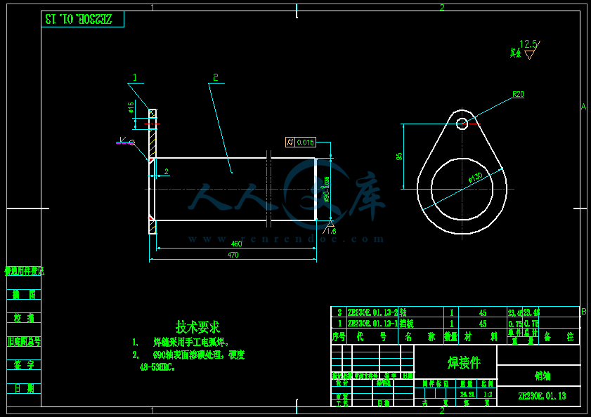


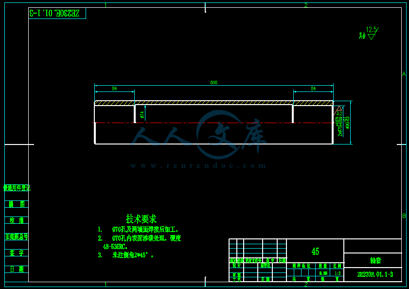

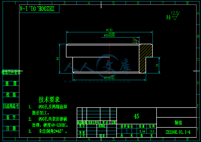


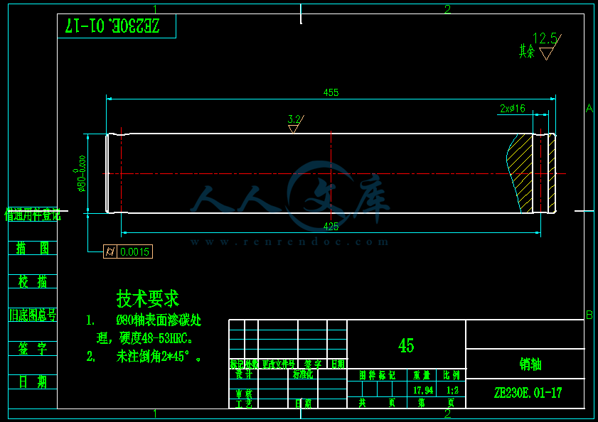
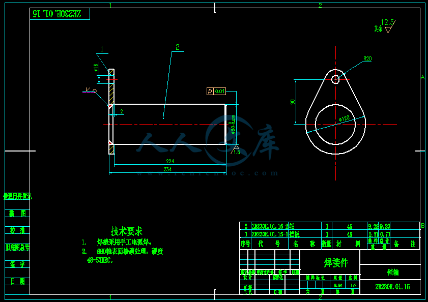
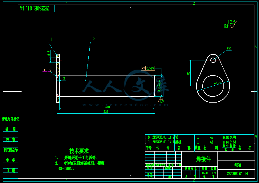


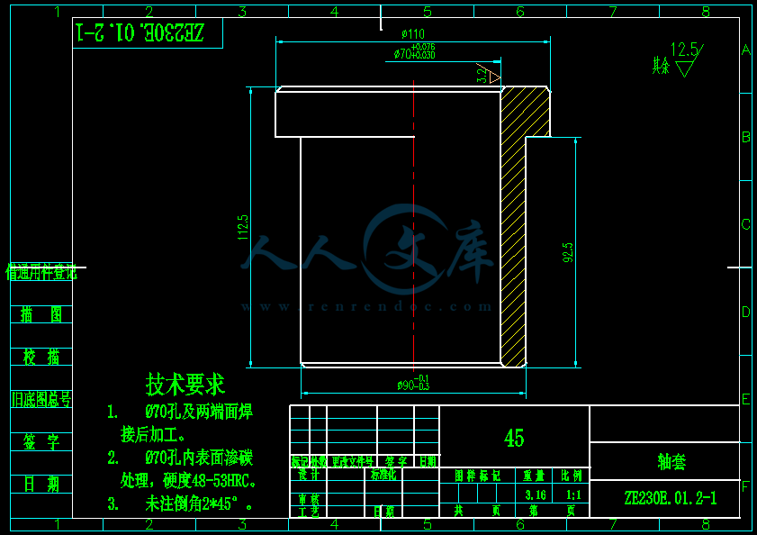


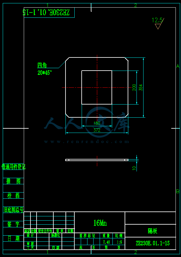
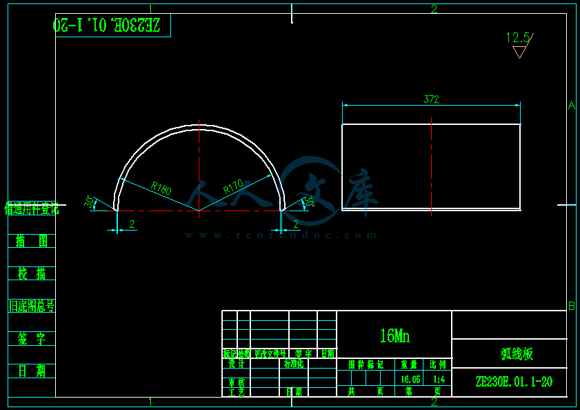

- 内容简介:
-
Control strategies of power system in hybrid hydraulic excavator Qing Xiao a, Qingfeng Wanga, Yanting Zhangb a The State Key Laboratory of Fluid Power Transmission and Control, Zhejiang University, 310027 Hangzhou, China b College of mechanical and electrical engineering, China University of Petroleum, 257061 Dongying, China Accepted 21 May 2007 Abstract Hybrid system, which has been successfully used in vehicles, is introduced to hydraulic excavators nowadays. The primary focus of this study is to investigate the control strategies of hybrid system used in hydraulic excavators. At first, the structure and working conditions of hybrid hydraulic excavators are analyzed. Based on the analyses, a control strategy named the engine constant-work-point is proposed and studied in a simulative experimental system. Then the control strategy named double-work-point is presented to overcome the limitations of the constant- work-point control strategy. The features and experimental results of the double-work-point control strategy show that the engines efficiency and the capacitors state of charge (SOC) cannot be optimized simultaneously. Thus a dynamic-work-point control strategy, which regulates the engines working point dynamically, is developed to make the system work better. Experimental results show that the dynamic-work-point control strategy can improve the distribution of engines working points, restrain the capacitors SOC and has little influence on the performance of the system. 2007 Elsevier B.V. All rights reserved. Keywords: Hybrid system; Excavator; Engine constant-work-point control strategy; Double-work-point control strategy; Dynamic-work-point control strategy 1. Introduction Energy is consuming up and pollution is more and more serious in the world range. So research on the energy saving of construction machinery, especially hydraulic excavators, is very necessary and urgent due to their high energy consumption and bad exhaust. Traditional energy saving methods for hydraulic excavator cannot raise the effect on a large scale if there are no major technology breakthrough 1,2. It can be concluded from different working conditions of a hydraulic excavator (condition data derived from the actual work) that its load power varies periodically in a large range, thus the working condition of the engine also changes periodically and therefore cannot always remain in a high efficiency state. Thats the main cause that hydraulic excavators have low fuel economy. Hybrid system, which consists of an engine and an electric motor, has the potential of improving fuel economy by operating the engine in an optimum efficiency range and it has been successfully applied in vehicles. So equipping hydraulic excavators with the hybrid system provides a new way to achieve energy savings. Recently, research on the structure, control strategy and energy management of hybrid system in hydraulic excavators has been carrying out 39. Among them, the control strategy, which determines the working state of the components in the power system directly and affects the energy consumption of hydraulic excavators ultimately, is one of the major concerns. This paper mainly deals with the control strategies of a hybrid system in hydraulic excavators. We present these control strategies step by step. When a hybrid system is implemented, the fluctuation of load power is absorbed by the accumulator of the power system, making the engine only output the averaged load power. Thus the control strategy of working at a constant high efficiency point can be realized for the engine with the benefit of increasing the efficiency of the engine and system. However, under the control strategy of working at a constant high efficiency point, since the chosen working power of the enginecannot beexactlythesameastheaverage loadpower,the state of charge (SOC) of the accumulator will rise or drop after Automation in Construction 17 (2008) 361367 /locate/autcon Corresponding author. Tel.: +86 571 87951314 6204; fax: +86 571 87951941. E-mail address: (Q. Xiao). 0926-5805/$ - see front matter 2007 Elsevier B.V. All rights reserved. doi:10.1016/j.autcon.2007.05.014 one work cycle. After a long time of work, the SOC will exceed its working range, and the system can work normally no longer. To overcome this limitation, we can employ a double-work- point control strategy, that is, the engine works at one high- powerpointandonelow-powerpointinthehighefficiencyarea. When the SOC of the accumulator exceeds the assigned upper limit, the engine switches to its low-power point; when the SOC comes to the assigned lower limit, the engine switches to its high-power point. In this way the engines efficiency remains relatively high and the SOC of the accumulator wont exceed its working range. Under the double-work-point control strategy, the engine will switch between two working points frequently if the assigned working range of the accumulator is narrow. This is not desirable considering the stability of the system. On the other hand, if the working range of the accumulators SOC is set wide, the efficiency and cycle-life of the accumulator will be deteriorated. Thus a control strategy, which regulates the engines working point dynamically, has been developed to overcome this drawback in our lab. Under this control strategy, the engines working point changes dynamically in a high efficiency range according to the accumulators SOC, and the problems encountered in the double work-point control strategy can be avoided. The paper is organized as follows. Section 2 is devoted to the structure and working conditions of the hybrid system. Section 3 presents the engine constant-work-point control strategy. The engine double-work-point control strategy is demonstrated in section 4. The engine dynamic-work-point control strategy is addressed in section 5 together with experimental results. Finally, conclusions are provided in section 6. 2. Structure and working condition of the power system 2.1. Structure of the power system The structure of the power system is shown in Fig. 1. The engine and electric motor drive the hydraulic pump in a parallel hybrid style. The mechanical power of the engine outputs to the hydraulic pump directly, which reduces energy conversion loss comparing with the serial hybrid system. The electric motor, which can work as a motor orgenerator, outputs energy together with the engine or converts the engines redundant mechanical energy to electrical energy and stores in the capacitor. 2.2. Working condition of the power system Fig. 2 shows the normalized output power (P/Pmax) of the power system, where P is output power of the hydraulic excavator, and Pmaxis the rated power of the engine. The data are derived from the actual digging work cycles of a certain hydraulic excavator. It can be seen from the figure that the output power fluctuates greatly and periodically, and the cycle time is only about 18 s. Hence a capacitor, which has a fast chargedischarge speed and long cycle-life, is used as an accumulator to balance the fast power fluctuation in the power system. 3. Engine constant-work-point control strategy 3.1. Details of the control strategy According to the above analyses, the load power of hydraulic excavator is regular and cyclic. The load power in one cycle can be taken as two constituent parts: the average value plus the fluctuation. So it is reasonable to employ the engine constant- work-point (constant rotational speed and constant torque) control strategy for the hybrid hydraulic excavator, in which the Fig. 1. Schematic of parallel hybrid hydraulic excavator. Fig. 2. Output power of the power system in digging working condition. Fig. 3. Mechanical characteristic curve of electric motor. 362Q. Xiao et al. / Automation in Construction 17 (2008) 361367 engine works at a constant point to supply the load average power, and the fluctuating power is supplied by the electric motor-capacitor. In this way the engine can always work in its high efficiency range with high fuel economy and low emission. Under the control strategy of constant-work-point, the rotational speed of the engine is a preset value. Since the electric motor is connected with the engine coaxially, its rotational speed is the same as the engine. It can be seen from Fig. 1 that the torque of the engine is the difference of the torque of the hydraulic pump and that of the electric motor. When the load changes, we should adjust the torque of the electric motor to maintain the engines torque constant. This can be realized by changing the revolutional slip of the electric motor via regulating its synchronous rotational speed. Fig. 3 shows the mechanical characteristic curve of the electric motor. Notations in the figure are the following: nRotational speed MTorque nmActual rotational speed of the electric motor nRevolutional slip Here nmis a constant. As shown in the figure, the mechanical characteristic curve moves up or down when the synchronous rotational speed of the electric motor changes, and the output torque of the electric motor alternates accordingly. When the synchronous rotational speed is lower than nm, n becomes negative and the torque of the electric motor also becomes negative (the electric motor works as a generator). Otherwise n and the torque of the electric motor are positive. The relationship between n and the torque of the electric motor is decided by the motors mechanical characteristic curve. Fig. 4 presents the block diagram of engine torque in the engine constant-work-point control strategy. Notations used in the figure are the following: MeiTarget torque of the engine nmiTargetsynchronousrotationalspeedoftheelectricmotor nmoActualsynchronousrotationalspeedoftheelectricmotor nmRevolutional slip of the electric motor MmOutput torque of the electric motor MpTorque of the hydraulic pump MeoOutput torque of the engine Givena targettorqueofthe engineMei,thetargetsynchronous rotational speed of the electric motor nmiis calculated by the control algorithm (Here the PID is chosen); the synchronous speed of the electric motor is controlled by one vector controller; the difference between nmoand nmis nmand the electric motor outputs the torqueMmaccording to nm; then the engine outputs torque Meoto drive the hydraulic pump together with the electric motor. 3.2. Experimental system A simulative experimental bench, illustrated in Fig. 5, was established in our lab to study the control strategies for hybrid system. A proportional relief valve was used to simulate the load pressure of hybrid system. The simulation of load flow rate was realized by alternating the displacement of the hydraulic pump. Notations in the figure are the following: ppPressure of the hydraulic pump QFlow rate of the hydraulic pump M1Torque of Mot1 M2Torque of Mot2 UVoltage of the capacitor ICurrent of the capacitor f1Frequency control signal of Inv1 f2Frequency control signal of Inv2 qcDisplacement control signal of the hydraulic pump pcPressure control signal of the proportional relief valve For the convenience of control, we used a 37 kW variable- frequency electric motor Mot1, which was controlled by the inverter Inv1, as the replacement of the engine in Fig. 1. A variable-frequency electric motor, Mot2, with the power of Fig. 4. Control block diagram of engine torque control. Fig. 5. Schematic of the experimental system. 363Q. Xiao et al. / Automation in Construction 17 (2008) 361367 22 kW, was controlled by the inverter Inv2. Mot1 and Mot2 were connected in parallel to drive the hydraulic pump. A set of capacitors, with the capacity of 12.5 F and maximum voltage of 400 V, was used as the accumulator of the experimental system. The main control unit of the system was composed of one industry control computer, one data acquisition card and one data control card. Appropriate sensors were used to measure pp, n, Q, M1, M2, U, I, etc. The controller collected and processed data from the sensors and output the control signals f1, f2, qc, pc to control the rotational speed of the electric motors and flow rate together with the pressure of the hydraulic system. 3.3. Experimental results of the control strategy Based on the analyses, the engine constant-work-point control strategy was studied in the experimental system mentioned above. Fig. 6 shows the normalized flow rate (Q/ Qmax) and pressure (p/pmax) of the hydraulic pump in one work cycle (the data were derived from actual work cycle of a hydraulicexcavator). We converted the flow rate and pressure to the corresponding signals qcand pcfor the hydraulic pump and proportional relief valve in the experiment. Fig. 7 presents the comparison of normalized output power (P/Pmax) of Mot1, Mot2 and the capacitor. It can be seen that the output power of Mot1 fluctuates little during the cycle, indicating the working point of the engine is almost constant, and the output power of Mot2 is fluctuant. Fig. 7 also shows that the output power of Mot2 is always lower than that of the capacitor; the difference between them is the power conversion loss. Fig. 7 shows that the engine constant-work-point control strategy is basically feasible, but the output power of Mot1 is not exactly constant. The reason is that the algorithm of engine torque control is a simple PID and not proper enough. Improving the control algorithm is the emphasis of our next study. 4. Engine double-work-point control strategy Since the chosen working power of the engine cannot be exactly the same as the average of the load power, the SOC of the capacitor will exceed its working range after a long time of work. We further developed a control strategy in which, when the SOC exceeds its upper limit, the engine switches to a low- power working point in the high efficiency range, and, when the SOC comes to its lower limit, the engine switches to a high- power working point in the high efficiency range, and it is named as the engine double-work-point control strategy. The double-work-point control strategy was studied in our experimental system mentioned above. Its control method is the same as the constant-work-point control strategy, that is, the engines torque is stabilized via adjusting the synchronous rotational speed of the electric motor. The experimental curves are shown in Fig. 8, where the engines high-power working Fig. 6. Pressure and flow rate of the hydraulic pump. Fig. 7. Comparison of the output power. Fig. 8. Experimental curves of double-work-point control strategy. Fig. 9. Engines efficiency map. 364Q. Xiao et al. / Automation in Construction 17 (2008) 361367 point is Ph, the low-power working point is Pl, P/Pmaxis the normalized output power of Mot1 and S is the SOC of the capacitor. The figure illustrates working points of Mot1 switching between Pland Phaccording to the capacitors SOC and the switch style is consistent with the above analyses, which indicates the feasibility of this control strategy. As in the engine constant-work-point control strategy, this control strategy cannot stabilize working point Pland Phat exactly constants either. It can be deduced from the experimental results that the engine will switch between the two working points frequently if the working range of the capacitors SOC is narrow; this is not favorable for the systems stable work. If the working range of the capacitors SOC is wide, the efficiency and working life of thecapacitorwillbedeteriorated.Thus,acontrolstrategy,which adjusts the engine working point dynamically, was developed to optimize the engines working state and capacitors SOC. 5. Engine dynamic-work-point control strategy 5.1. Details of the control strategy Under this control strategy, the engines working point is dynamically adjusted according to the capacitors SOC after every work cycle. There are two goals of this control strategy. One is to ensure the distribution of the engines working points in or near its high efficiency range. The other is to restrain the variation range of the capacitors SOC. The control strategy is listed below. Step 1: Calculate the load average power and set the upper and lower limits of the engines power.The overlapping zone between the power limits and the high efficiency area of the engine is set as the engines working area, as shown by the dashed line area H in Fig. 9. The coordinates of Fig. 9 are normalized rotational speed (n/nmax) and the torque (M/Mmax). Step 2: Choose engines initial working point P0(ne,Me) in the area H according to the load average power. Step 3: Set the initial capacitors SOC S0and the sensitivity St. Step 4: After ith (i=1, 2, 3) work cycles, if the current SOC Siand the former SOC Si1meet Eqs. (1) and (2), the system continues to work without any parameter changes; otherwise, the engines working point is adjusted by using Eq. (3). jSi? Si?1jVDSt;1 jSi? S0jVDSt;2 Pi1ne;Me Pine;Me ? KcDS;SiNSi?1Me ? KdDS;SibSi?1 ? 3 where: Pi+1(ne, Me) Engines working point after ith work cycles Pi(ne, Me) Engines working point after (i1)th work cycles KcAdjustment coefficient when engines power is high KdAdjustment coefficient when engines power is low SSOC difference, equal to SiSi1 Step 5: Move the engines working point into or near the H areaalongthepowercontourifnecessary(asshowninFig.9). Step 6: Regulate the control signals of hydraulic system to drive the load according to the changed engines working point. Step 7: As the engines working point is regulated along the power contour, the engines efficiency may be sacrificed to fulfill the need of the load if the adjusted hydraulic control signals are out of the control range. The flowchart of the control strategy is shown in Fig. 10. As the engines working point Pi+1(ne,Me) is regulated toPi+1 (ne,Me) Fig. 10. Flowchart of the control stra
- 温馨提示:
1: 本站所有资源如无特殊说明,都需要本地电脑安装OFFICE2007和PDF阅读器。图纸软件为CAD,CAXA,PROE,UG,SolidWorks等.压缩文件请下载最新的WinRAR软件解压。
2: 本站的文档不包含任何第三方提供的附件图纸等,如果需要附件,请联系上传者。文件的所有权益归上传用户所有。
3.本站RAR压缩包中若带图纸,网页内容里面会有图纸预览,若没有图纸预览就没有图纸。
4. 未经权益所有人同意不得将文件中的内容挪作商业或盈利用途。
5. 人人文库网仅提供信息存储空间,仅对用户上传内容的表现方式做保护处理,对用户上传分享的文档内容本身不做任何修改或编辑,并不能对任何下载内容负责。
6. 下载文件中如有侵权或不适当内容,请与我们联系,我们立即纠正。
7. 本站不保证下载资源的准确性、安全性和完整性, 同时也不承担用户因使用这些下载资源对自己和他人造成任何形式的伤害或损失。

人人文库网所有资源均是用户自行上传分享,仅供网友学习交流,未经上传用户书面授权,请勿作他用。
 川公网安备: 51019002004831号