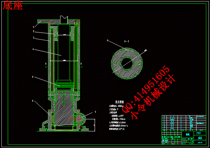
零件平键.dwg
零件平键.dwg

液压机械手的设计【7张CAD图纸+说明书】【含开题报告和翻译】

收藏

压缩包内文档预览:
预览图
编号:271530    类型:共享资源    大小:832.09KB    格式:RAR    上传时间:2014-04-07 上传人:好资料QQ****51605 IP属地:江苏
45
积分
关 键 词:
液压 机械手 设计
资源描述:

【温馨提示】 购买原稿文件请充值后自助下载。

[全部文件] 那张截图中的文件为本资料所有内容,下载后即可获得。


预览截图请勿抄袭,原稿文件完整清晰,无水印,可编辑。

有疑问可以咨询QQ:414951605或1304139763


   液压机械手是模仿人的手部动作,按照给定的程序、轨迹通过液压系统实现抓取和搬运操作的自动装置。
   本次设计的液压传动机械手根据规定的动作顺序,综合运用所学的基本理论、基本知识和相关的机械设计专业知识,完成对机械手的设计,并绘制必要装配图、液压系统图、。机械手的机械结构采用油缸、螺杆、导向筒等机械器件组成;在液压传动机构中,机械手的手臂伸缩采用伸缩油缸,手腕回转采用回转油缸,立柱的转动采用齿条油缸,机械手的升降采用升降油缸,立柱的横移采用横向移动油缸;通过控制电磁阀的开关来控制机械手进行相应的动作循环,当按下连续停止按钮后,机械手在完成一个动作循环后停止运动。
   本设计拟开发的上料机械手可在空间抓放物体,动作灵活多样,可代替人工在高温和危险的作业区进行作业,可抓取重量较大的工件。可以改善劳动条件,避免人身事故。可以减少人力,并便于有节奏的生产。

  关键词: 机械手;液压;控制回路

Abstract
   Hydraulic robot mimic is the hand movements which in accordance with a given program, the path through the hydraulic system to achieve automatic device to capture and handling operations.
   The design of hydraulic drive manipulator movements under the provisions of the order , use the basic theory, basic knowledge and related mechanical design expertise comprehensively to complete the design,and drawing the necessary assembly, hydraulic system map, PLC control system diagram . Manipulator mechanical structure using tanks, screw ,guide tubes and other mechanical device component ;In the hydraulic drive bodies ,manipulator arm stretching using telescopic tank ,rotating column of tanks used rack ,manipulator movements using tank movements ,the column takes the horizontal movement of tanks ; through the control of the solenoid valve to control the switch manipulator corresponding moves cycle ,after press the row stop button , the manipulator complete a cycle of action to stop after the hole campaign.
   The design of the proposed development of the information on the manipulator can grasp up in space objects ,flexible and varied movements ,can replace the artificial heat and dangerous operation conducted operations,and can grasp the larger work pieces . Can improve working conditions, avoid personal accident. Can reduce manpower, and to facilitate the there are-paced the production of.

Keywords: Manipulator ;Hydraulic;Control Loop


目  录
摘  要 III
Abstract IV
目  录 V
1 绪论 1
  1.1 机械手的基本概念的研究内容和意义 1
1.1.1 机械手的基本概念 1
1.1.2 机械手的研究意义 1
  1.2 机械手的发展现状及应用 1
1.2.1  世界机器人发展状况 1
1.2.2 我国工业机器人的发展 2
  1.3  本课题达到的要求 2
2 液压机械手主要结构的机械设计 4
  2.1 臂力的确定 4
  2.2 确定工作范围 4
  2.3 确定运动速度 4
  2.4 手臂的配置形式 4
  2.5 位置检测装置的选择 5
  2.6 驱动与控制方式的选择 5
  2.7 本章小结 5
3 手部结构 7
  3.1 概述 7
  3.2 设计时应考虑的几个问题 7
  3.3 驱动力的计算 8
  3.4 两支点回转式钳爪的定位误差的分析 9
  3.5 本章小结 9
4 腕部的结构 11
  4.1 概述 11
  4.2 腕部的结构形式 11
  4.3 手腕驱动力矩的计算 11
  4.4 本章小结 13
5 臂部的结构 14
  5.1 臂部概述 14
  5.2 手臂直线运动机构 14
5.2.1 手臂伸缩运动 14
5.2.2 导向装置 15
5.2.3 手臂的升降运动 16
  5.3 手臂回转运动 17
  5.4 手臂的横向移动 17
  5.5 臂部运动驱动力计算 17
5.5.1 臂水平伸缩运动驱动力的计算 17
5.5.2 臂垂直升降运动驱动力的计算 18
5.5.3 臂部回转运动驱动力矩的计算 18
6 液压系统的设计 20
  6.1 液压系统简介 20
  6.2 液压系统的组成 20
  6.3 机械手液压系统的控制回路 20
6.3.1 压力控制回路 20
6.3.2 速度控制回路 21
6.3.3 方向控制回路 21
  6.4 机械手的液压传动系统 21
6.4.1 上料机械手的动作顺序 21
6.4.2 自动上料机械手液压系统原理介绍 22
  6.5 机械手液压系统的简单计算 24
  6.6 双作用单杆活塞油缸 24
  6.7 无杆活塞油缸(亦称齿条活塞油缸) 27
6.7.3 单叶片回转油缸 27
6.7.4 油泵的选择 28
6.7.5 确定油泵电动机功率N 29
7 结  论 30
致       谢 31
附  录 33

1 绪论
1.1 机械手的基本概念的研究内容和意义
  1.1.1 机械手的基本概念
   液压机械手,从本质上来说是属于工业机器人的范围的,机器人问题是最近几十年的热门研究课题。它包括了机械工程、计算机科学、电子工程和自动控制以及人工智能等多种学科,体现了机电一体化技术的最新成就,是当代科学技术发展最活跃的范围之一,也是我国科技界跟踪国际高技术发展的重要课题。
   “机械手”(Machanical Hand):大部分是指附属于主机、程序固定的自动抓取、操作装置(我国一般称作机械手或专用机械手)。比如自动生产线、自动机的上下给料系统,加工中心自动化装置[1]。
  1.1.2 机械手的研究意义
   1.可以提高生产过程的自动化程度。
   应用机械手有利于在自动生产线中实现材料的传送、工件的装卸、刀具的更换、以及机器的装配等的自动化程度,从而提高劳动生产率,降低生产成本。
   2.可以改善劳动条件,避免人身事故。
   3.可以减少人力,并便于有节奏的生产。
   4.用液压系统来控制机械手,比一般的机械控制具有更好的稳定性,并且控制的精确度更高。
   5.运用机械手可以实现连续的生产,而大大提高在生产线的工作的时间,从而能大幅提高劳动的生产率。
1.2 机械手的发展现状及应用
   机械手的迅速发展是因为它的积极作用正逐渐被人们所认可;第一,它能部分代替体力人工操作;第二,它可以按照生产工艺的要求,按照一定的程序,时间和位置来完成工作的传送和装卸;第三,它能操作必要的器具进行焊接和装配。从而改善人们的劳动条件,显著的提高劳动生产率,加快实现工业生产机械化和自动化的步伐。因此,各先进工业国家都对此十分重视,投入大量的人力物力进行研究和应用。尤其在高温、高压、粉压、噪音以及带有放射性的污染的场合应用得更为广泛。在我国,近几年来也有较快的发展,并取得一定的效果,受到机械工业和铁路工业部门的重视[2]。
  1.2.1  世界机器人发展状况
   国外机器人领域发展近几年有如下几个趋势:
   (1).  工业机器人性能不断提高(高速度、高精度、高可靠性、便于操作和维修),而单机价格不断下降。
   (2).机械结构向模块化、可重构化发展。例如关节模块中的伺服电机、减速机、检测系统三位一体化;由关节模块、连杆模块用重组方式构造机器人整机;国外已有模块化装配机器人产品问市。
   (3).工业机器人控制系统向基于PC机的开放型控制器方向发展,便于标准化、网络化;大大提高了系统的可靠性、易操作性和可维修性。
7 结  论
   液压机械手是一种模仿人体上肢部分功能,按照预定要求输送工件或者握持工具进行操作的自动化技术设备,它可以代替手的繁重劳动,改善劳动条件,提高劳动生产率和自动化水平。有着广阔的发展前途。本课题通过机械手进行液压传动原理设计,实现机械手代替人力进行工作。设计中,在查阅大量相关文献的基础上,完成了以下工作:根据液压机械手的特殊性对其造型等方面的设计需求进行分析,从整体上把握其设计原则;然后对不同的功能区域进行单独的研究分析,总结出符合工程学要求的设计理论;最后将整体的设计分析和每一部分的设计相结合,寻找有效的结合点并进行统一协调,最终设计出高质量、高档次的产品。完成了对液压系统的各液压元件的设计、计算及选型。对液压机械手相关附件作了简要设计。液压机械手设计理论部分虽然完成了,但还需要进行实际的应用检验,并且找出其中的不足加以修改。


致       谢
   本篇设计是在黄敏副教授和朱启兵副教授的指导下完成的,在此过程中,两位老师给予了我很多帮助。从课题的提出开始,两位老师就对我进行了无私的指导和帮助,不厌其烦的帮助进行论文的修改和改进。特别是在图纸设计的过程中,朱老师给了我很多很多指导,指出多处错误并不断帮助我修改。直到最后的定稿,老师还是多次查看,指导我规范格式。两位老师积极严谨的工作态度,让我在设计过程中少走很多弯路,使我能按时完成各步骤工作,最终完成毕业设计。
   另外,我还要感谢我的班主任马老师,对我学习和生活上的关心。马老师总是能在我遇到困难的时候及时的给予我帮助。在写论文期间,马老师经常督促我们要每天都写论文,不要到最后赶工,直到最后几天看到许多同学都赶工,才知道马老师对我的的督促是对的。
   当然,还要感谢我的同学们,感谢我的同学们在我又不懂的时候放下手头上的论文,来教我,让我感受到同学的友谊。
   毕业在即,再感谢所有支持和帮助过我的领导、老师、同学们。


参考文献
张建民. 工业机器人[M].  北京. 北京理工大学出版社, 1992.
天津大学《工业机械手设计基础》编写组. 工业机械手设计基础 [M]. 天津 天津科学技术出版社, 1981.
索罗门采夫. 工业机器人图册[M]. 北京. 机械工业出版社, 1993.
成大先. 机械设计图册[M]. 山东. 化学工业出版社, 2002.
金茂箐. 我国工业机器人发展现状[J]. 机器人技术与应用, 2001(4)24~28.
王田苗. 工业机器人发展思考[J]. 机器人技术与应用, 2004(2):23~25.
杰克. 机械与机构的设计原理[M]. 北京.机械工业出版社, 1985.
王玉新.  机构创新设计方法学[M]. 天津.天津大学出版社, 1996.
邓星钟. 机电传动控制[M]. 武汉.华中科技大学出版社,  2002.  
马香峰. 机器人结构学[M] . 北京.机械工业出版社, 1991.
李瑞峰.21世纪--中国工业机器人的快速发展时代[J]. 中国科技成果,  2001(18):34~38.
乔东凯 黄崇林.  移动式工业机器人设计的动力学分析[J]. 茂名学院学报, 2003(3):65~76.
B. Riveiro, An innovative method for remote measurement of minimum vertical underclearance  in routine bridge inspection[J], ELSEVIER, 2012(25): 34-40.
Dhananjay E. Upasani,  Development of Remote Control System for Bridge Inspection Using Robot and Digital Image Processing Technology[J],  International Journal of Computer Applications, 2010(1): 18.
Structures Evaluation Services Bureau, Special Issue on Nondestructive Evaluation and Testing for Bridge Inspection and Evaluation, 2012(17): 827-828.
Bedford A, Fowler W. Engineering Mechanics: Vol 2: Dynamics[M]. New York : Addison Wesley Publishing Company Inc, 2006(8):10.


内容简介:
COMBINATION OF ROBOT CONTROL AND ASSEMBLY PLANNING FOR A PRECISION MANIPULATOORAbstractThis paper researches how to realize the automatic assembly operation on a two-finger precision manipulator. A multi-layer assembly support system is proposed. At the task-planning layer, based on the computer-aided design (CAD) model, the assembly sequence is first generated, and the information necessary for skill decomposition is also derived. Then, the assembly sequence is decomposed into robot skills at the skill-decomposition layer. These generated skills are managed and executed at the robot control layer. Experimental resulte show the feasibility and efficiency of the proposed system.Keywords :Manipulator Assembly planning Skill decomposition Automated assembly1IntroductionOwing to the micro-electro-mechanical systems (MEMS) techniques, many products are becoming very small and complex, such as microphones, micro-optical components, and microfluidic biomedical devices, which creates increasing needs for technologies and systems for the automated assembly have been focused on microassembly technologies. However, microassembly techniques of high flexibility, efficiency, and reliability skill open to further research. This paper researches to how to realize the automatic assembly operation on a two-finger micromanipulator. A muli-layer assembly support system is proposed.Automatic assembly is a complex problem which may involve many different issues, such as task planning, assembly sequences generation, execution, and control, etc. It can be simply divided into two phases, the assembly planning and the robot control. At the assembly-planning phase, the information necessary for assembly operation, such as the assembly sequence, is generated. At the robot control phase, the robot is driven based on the information generated at the assembly-planning phase, and the assembly operations are conducted. Skill primitives can work as the interface of assembly planning to robot control. Several robot systems based on skill primitives have been reported. The basic idea behind these systems is the robot programming. .Robot movements are specified as skill primitives, based on which the assembly task is manually coded into programs. With the programs, the robot is control to assembly tasks automatically. A skill-based micromanipulation system has been developed in the authors lab, and it can realize many micromanipulation operations. In the system, the assembly task is manually discomposed into skill sequences and complied into a file. After importing the file into the system, the system can automatically execute the assembly task. This paper attempts to explore a user-friendly, and at the same time easy, sequence-generation method, to relieve the burden of manually programming the skill sequence.It is an effective method to determine the assembly sequence from geometric computer-aided design (CAD) models. Many approaches have been proposed. This paper applies a simple approach to generate the assembly sequence. It is not involved with the low-level data structure of the CAD model, and can be realized with the application programming interface (API) functions graph among different components is first constructed by analyzing the assembly model, and then, possible sequences are searched, based on the graph. According to certain criterion, the optimal sequence is finally obtained.To decompose the assembly sequence into robot skill sequences, some works have been reported. In Nnaji et al.work, the assembly task commands are expanded to more detailed commands, which can be as robot skills, according to a predefined format. The decomposition approach of Mosemann and wahl is based on the analysis of hyperarcs of AND/OR graphs representing the automatically generated assembly plans. This paper proposes a method to guide the skill decomposition .The assembly processes of parts are grouped into different start atate and target of the workflow, the skill generator creates a series of skills that can promote the part to its target state. The hierarchy of the system proposed here, the assembly information on how to assemble a product is transferred to the robot through multiple layers. Te top layer is for the assembly-task planning. The information needed for the task planning and skill generation are extracted from the CAD model and are saved in the database. Base on the CAD model, the assembly task squences are generated. At the skill-decomposition layer, tasks are decomposed into skill sequences. The generated skills are managed and executed at the robot control layer.2 Task planningSkills are not used directly at the assembly-planning phase, the concept of a task is used. A task can fulfill a series of assembly operations, for example, from locating a part, through moving the part, to fixing it with another part. In other words, one task includes many functions that may be fulfilled by several different skills. A task is defined as:T = (Base Part; Assembly Part; Operation)Based-part and Assembly-Part are two parts that are assembled together. Base-part is fixed on the worktable, while Assembly-Part is handled by robots end- effector and assembled onto the Base-Part. Operation describes how the Assembly-Part is assembled with the Base-Part; Operation=Intertion-T,serew-T,align-T,.The structure of microparts is usually uncomplicated, and they can be modeled by the constructive solid geometry (CAG) method. Currently, many commercial CAD software packages can support 3D CSG modeling. The assembly model is represented as an object that consists of two parts with certain assembly relations that define how the parts are to be assembled. In the CAD model, the relations are defined by geometric constraints. The geometric information cannot be used directly to guide the assembly operation-we have to derive the information necessary for assembly operations from the CAD model.Through searching the assembly tree and geometric relations (mates relations) defined in the assemblys CAD model, we can generate a relation graph among parts, for example, In the graph, the nodes represent the parts. If nodes are connected, it means that there are assembly relations among these connected nodes (parts).2.1 Mating directionIn CSG, the relations of two parts, geometric constraints, are finally represented as relations between planes and lines, such as collinear, coplanar, tangential, perpendicular, etc. For example, a shaft is assembled in a hole. The assembly relations between the two parts may consist of such two constraints as collinear between the centerline of shaft Lc-shaft and the centerline of hole Lc-hole and coplanar between the P-Shaft and the plane P-Hole. The mating direction is a key issue, for an assembly operation. This paper applies the following approach to compute the possible mating direction based on the geometric constraints (the shaft-in-hole operation of Fig. 3 is taken as an example):For a part in the relation graph, calculate its remaining degrees of freedom, also called degrees of separation, of each geometric constraint.For the conplanar constraint, the remaining degrees of freedom are R1= x,y,Rotz . For the collinear constraint, the remaining degrees of freedom are R2= z,Rotz. R1 and R2 can also be represented as R1= 1,1,0,0,0,1 and R20,0,1,0,0,1. Here, 1 means that there is a degree of separation between the two parts. R1R2= 0,0,0,0,1,and so, the degree of freedom around the z axis will be ignored in the following steps.In the ease that there is loop in the relation graph, such as parts Part5,Part6, and Part 7 in Fig. 2,the loop has to be broken before the mating direction is calculated. Under the assumption that all parts in the CAD model are fully constrained and not over-constrained, the following simple approach is adopted. For the part t in the loop, calculate the number of is in Nin=Ri1Ri2.Rin; where R is the remaining degrees of freedom of constraint k by part i. For example, in Fig. 2, given that the number of 1s in U is larger than U, then it can be regarded that the position of part 7 is determined by constraints between part 5 and part 6,while Part5 and Part6 can be fully constrained by constraints between Part 5 and Part 6. we can unite Part 5 and Part 6 as one node will be regarded as a single, but it is obvious that the composite node implies an assembly sequence.Calculate mating directions for all nodes in the relation graph. Again, beginning at the state that the shaft and the hole are assembled, separate the part in one degree of separation by a certain distance (larger than the maximum tolerance), and than check if interference occurs. Separation in both x axis and y axis of R1 causes the interference between the shaft and the hole. Separation in the +z direction raises on interference. Then, select the +z direction as the mating direction, which is represented as a vector M measured in the coordinate system of the assembly. It should be noted that , in some case, there may be several possible mating directions for a part. The condition for assembly operation in the mating direction at the assembled state, which can be checked simply with geometric constraints, the end condition is measured by force sensory information, whereas position information is used as an end condition.Calculate the grasping position. In this paper, parts are handled and manipulated with two separate probes, which will be discussed in the Sect.4, and planes or edges are considered for grasping. In the case that there are several mating directions, the grasping plans are selected as G1G2Gi, where Gi is possible grasping plane/edge set for the ith mating direction when the part is at its free state. For example, in Fig. 4, the pair planes P1/P1, P2/P2, and P3/P3 can serve as possible grasping planes, and then the grasping planes are P1/P1, P2/P2, P3/P3/P1/P1, P3/P3/P1/P1,P2/P2=P1/P1The approaching direction of the end-effector is selected as the normal vector of the grasping planes. It is obvious that not all points on the grasping plane can be grsped. The following method is used to determine the grasping area. The end-effector, which is modeled as a cuboid, is first added in the CAD model, with the constraint of coplanar or tangential with the grasping plane. Beginning at the edge that is far away from the Bae-Part in the mating direction, move the end-effector in the mating direction along the grasping plane until the end-effector is fully in contact with the part, the grasping plane is fully in contact with the end-effector, or a collision occurs. Record the edge and the distance, both of which are measured in the parts coordinate system.Separate gradually the two parts along the mating direction, which checking interference in the other degrees of separation, until no interference occurs in all of the other degrees of separation. There is obviously a separation distance that assures interference not to occur in every degree of separation. It is called the safe length in that direction. This length is used for the collision-free path calculation, which will be discussed in the following section.2.2 Assembly sequenceSome criteria can be used to search the optimal assembly sequence, such as the mechanical stability of subassemblies, the degree of parallel execution, types of fixtures, etc. But for microassembly, we should pay more attention to one of its most important features, the limited workspace, when selecting the assembly sequence. Microassembly operations are usually conducted and monitored under microscopy, and the workspace for microassembly is very small. The assembly sequence brings much influence on the assembly efficiency. For example, a simple assembly with three parts. In sequence a, part A is first fixed onto part B. In the case that part C cannot be mounted in the workspace at the same time with component AB because of the small workspace, in order to assemble part C with AB, component AB has to unmounted from the workspace. Then, component C is transported and fixed into the workspace. After that, component AB is transported back into the workspace again. In sequence b, there is no need to unmount pay part. Sequence a is obviously inefficient and may cause much uncertainty by an assembly sequence , the more inefficient the assembly sequence. In this paper, due to the small-workspace feature of microassembly, the number of times necessary for mounting of parts is selected as the search criteria to find the assembly sequence that has a few a number of times for the mounting of parts as possible. This paper proposes the following approach to search the assembly sequence. The relation graph of the assembly is used to search the optimal assembly sequence. Heuristic approaches are adopted in order to reduce the search times: Check nodes connected with more than two nodes. If the mating directions of its connected nodes are different, mark them as inactive nodes, whereas mark the same mating directions as active mating direction.Select a node that is not an inactive node. Mark the current node as the base node (part). The first base part is fixed on the workspace with the mating direction upside (this is done in the CAD model).Compare the size (e.g., weight or volume) of the base part with its connected parts, which can be done easily by reading the bill of materials (BOM) of the assembly. If the base part is much smaller, then mark it as an inactive node.Select a node connected with the base node as an assembly node (part). Check the mating direction if the base node needs to be unmounted from the workspace. If needed, update a variable In the CAD model, move the assembly part to the base part in the possiblemting direction, which checking if interference (collision) occurs. If interference occurs, mark the base node as an inactive node and go to step 2, whereas select the Operation type according to parts geometric features. In this step, an Obstacle Box is also computed. The box, which is modeled as a cuboid , includes all parts in the workspace. It is used to calculate the collicion-free path to move the assembly part, which will be introduced in the following section. The Obstacle Box is described by a position vector and its width, height, and length.Record the assembly sequence with Operation type, the mating direction, and the grasping position.If all nodes have been searched, then mark the first base node as an inactive node and go to step 2. If not, select a node connected with the assembly node. Mark it as an assembly node, and the assembly node that is same as the mating direction of the former assembly node. If there is, use the former mating direction in the following steps. Go to step 3. After searching the entire graph , we may have search assembly sequence s. Comparing the values of mount , the more efficient one can be selected. If there are N nodes in the relation graph of Fig. 2b , all of which are not classed as inactive node, and each node may have M mating directions, then it needs M computations to find all assembly sequences. But because, usually, one part only has one mating direction, and there are some inactive nodes, the computation should be less than Mn.It should be noted that, in the above computation, several coordinate systems are involved, such as the coordinates of the assembly sequences, the coordinates of the base part, and the coordinates, of the assembly. The relations among the coordinates are represented by a 4*4 transformation matrix , which is calculated based on the assembly CAD model when creating the relations graph. These matrixes are stored with all o the related parts in the database. They are also used in skill decomposition.3 Skill decomposition and execution3.1 Definition of skill primitiveSkill primitives are the interface between the assembly planning and robot control. There have been some definitions on skill primitives. The basic difference among these definitions is the skills complexity and functions that one skill can fulfill. From the point of view of assembly planning, it is obviously better that one skill can fulfill more functions. However, the control of a skill with many functions may become complicated. In the paper, two separate probes, rather than a single probe or process is not easy. In addition, for example, moving a part may involve not only the manipulator but also the worktable. Therefore, to simplify the control process, sills defined in the paper do not include many functions.More importantly, the skills should be easily applied to various assembly tasks, that is, the set of skill should have generality to express specific tasks. There should not be overlap among skill. In the paper, a skill primitive for robot control is defined as: Attribute -I, Action -i(Attribute -i), Si= Start -i(Attribute -i), End -i(Attribute -i) Condition -i(Attribute -i).Attribute I Information necessary for Si to be executed. They can be classified as required attributes and option attributes, or sensory attributes and CAD-model-driven attributes. The attributes are represented by global variables used in different layers.Action_I Robots action, which is the basic sensormotion. Many actions are defined in the system, such as Move_Worktable, Move_Probes, Rotation_Worktable, Rotation_Probes, Touch, Insert, Screw, Grasp, ect. For one skill, there is only one Action. Due to the limited space, the details of actions will not be discussed in the paper.Start_i The start state of Action_i, which is measured by sensor values.End_i The end state of Action_i, which is measured by sensor values.Condition_i The condition under which Action_i is executed.From the above definitions, we may find that skill primitives in the paper bobot motions with start state and end state, and that they are executed under specific conditions. Assembly planning in the paper is to generate a sequence of robot actions and to assign values to attributes pf thede actions.3.2 Skill decompositionSome approaches have been proposed for skill decomposition. This paper presents a novel approach to guide the skill decomposition. As discussed above, in the present paper, a task is to assemble the Assembly_Part with the Base_part. We define the process from the state that Assembly_Part is at a free state to the state it is fixed with Bese_Part as the assembly lifestyle of the Assembly_Part. In its assembly lifecycle, the Assembly_Part may be at different assembly states. Here shows a shafts sates show as blocks and associated workflows of an insertion task. A workflow consisting of group of skills pushes forward the Assembly_Part from one state to another state. A workflow is associated with a specific skill generator that is in charge of generating skills. For different assembly tasks, the same workflows may be uded, though specific skills generated for different tasks may be different.The system provides default task templates, in which default states are defined. These templates are imported into the system and instantiated after they are associated with the corresponding Assembly_Part. In some cases, some states defined by the default template may be not needed. For example, determined by the fixture, then the Free and In_WS states can be removed from the shafts assembly lifecycle. The system provides a tool for users to modify thede templates or generate their own templates. The tools user interface is displayed in.For a workflow, the start state is measured by sensory values, which the target state is calculated based on the CAD model and sensory attributes. According to the start state and target state, the generator generates a series of skills. Here, we use the Move workflow in as an example to show how skills are generated.After the assembly task (assembly lifecycle) is initiated, the template is read into the Coordinator. For the workflow Move, its start is Grasped, which implies that the Assembly_Part is grasped by the robots end-effector and, obviously, the position of the Assembly_Part is also obtained Its target state is Adjusted, which is the state immedictely before it is to be fixed with the Base_Part. At the Adjusted atate, the orientation of the Assembly_Part is determinedby the mating direction, which the position is determined by the Safe Length. These values have been caluated in the task planning layer and are stored in a database. When the task template is imported, these valued are read into the memory at Coordinate and transformed into the coordinated of the workspace.There is an important and necessary step that hasto be performed in the skill decomposition phase-the generation of a collision-free path. Here, we use a straight-line path, which is simple and easy calculated. Assume that P3 is the position of the Assembly-part at the Adjusted state and P0 is the position at the Grasped state. The following approach is applied to generate the path:Based on the orientation of the Assembly-Part and mating direction, select skills (Rotate-Table or Rotate-Probes) to adjust the orientation of the part and assign values to the attributes of these skills.Based on the Obstacle Box, mating direction, real position/orientation of the Assembly-Part, the intermediate positions P1 and P2 need to be calculated.For each segment path, verify whether the Move-Table skill (for a large range) or the Move-Probe skill (for a small range) should be used.Generate skill lists for each segment and assign values to these skills.3.3 Execution of skillsAfter a group of skills which can promote the part a specific state are generated, these skills are transferred to the Skill Management model. The system promotesone or several skills into the On Work Skill list and simultaneously dispatches them to the micromanipulator. Once the skill has been completed by the robot, the system removes it from the On Work Task list and places it into the Completed Task list. After all of these skills have been completed, the state of the part is updated. For some states, skill execution and skill generation can be conducted in parallel. For example, for the Insertion lifestyle, if the parts position information is obtained, skills for the move workflow can be generated parallel with the execution of skills generated for the Grasp workflow.The assembly process id not closed to user. With the proposed skills management list structure, user can monitor and control the assembly process easily. For example, for the adjustment or the error recovery, users can suspend the ongoing skill to input commands directly or move the robot in a manual mode.4 Experiment4.1 Experimental platformThe experimental platform used in the paper. For microassembly operations, the precision and workspace are tradeoffs. In order to acquire both a large workspace and high precision, the two-stage control approach is usually used. These systems usually consist of two different sets of actuators; the coarse one, which is of large workspace but lower precision, and the fine one, which is of small workspace but higher precision. In our system, the large-range coarse motion is provided by a planar motion unit, with a repeatability of 2m in the x and y directions, which is driven by two linear sliders made by NSK Ltd. The worktable can also provide a rotation motion around the axis, which is driven by a stepper motor with a maximum resolution of 0.1 step.In the manipulator, two separate probes, rather than a single probe or parallel jaw gripers, are used to manipulate the miniature parts. The two probes are fixed onto stepper motors with a maximum resolution of 0.05 step. The two motors are then fixed onto the parallel motion meachanism respectively. It is a serial connection of a parallel-hexahedron link and a parallelogram link. When the 1,2 and 3 are small enough, the motion of the end-effector can be considered as linear motion.The magnetic actuator to drive the parallel meachanism consists of an air-core coil is fixed onto the base frame. The magnetic is attached to the parallel link , which the coil is fixed onto the base frame. The magnetic levitation is inherently unstable, because it is weak to external disturbances due to its non-contact operation in nature. To minimize the effect of external disturbances, a disturbance-observer-based method is used to control our micromanipulator.Laser displacement sensors are used to directly measure the probes position. The reflector is attached to the endeffector. Nano-force sensors produced by the BL AUTOTEC company are used to measure the forces. The position resolution of the micromanipulator is 1 um. The maximal resolution of the force is 0.8 gf, and the maximal resolution of the torque is 0.5 gfcm. A more detailed explanation on the mechanism of the mainpulatoe can be found. All assembly operations are conducted under a microscope SZCTV BO61 made by the Olympus Company. The image information is captured by a Sharp GPB-K PCI frame grabber, which works at 25 MHz.An assembly with three components is assembled with the proposed manipulator. It is a wheel of a micromobile robot developed in the authorslab. The following geometric constraints are defined in the CAD model; collinear between CL-cup and CL-axis, collinear between CL-gear and CL-axis, conplanar between Plane-cup and Plane-gear-l, coplanar between Plane-gear-l and Plane-axis. According to the above geometric constraints, the three parts construct a loop in the relation graph. The CAD model is created with the commercial software Solidworks 2005, and its API functions are used to develop the assembly planning model. The assembly Information database is develop with Oracle 9.2. Model involved with skill generation are developed with Visual Basic6.0. The skill-generation model are run with Windows 2000 on an HP workstation with a CPU of 2.0G Hz and memory of 1.0 GB. Assuming that the positions of parts are available beforehand, it took about 7 min to generate the skill sequence. The generated assembly sequence is to assemble the gear onto the axis, and then assemble the cup onto the axis and the gear. In the assembly operation, the parts are placed on the worktable with special fixture and then transported into the workspace, so that their initial position and orientation can be assured. Therefore, in the experiment, all of the skill sequences for the different parts can be generated and then transferred to the Skill Management unit. The skill instransmitted to the micromanipulator through TCP/IP communication. Because the controller of the micromanipulator is run on DOS, the WTTCP tools kit are adopet to develop the TCP/IP communication protocol.Because, currently, the automanted control of the fixtures is not realized yet, the parts have to be fixed manually onto the worktable. The promotion between different tasks (assembly lifecycle of different parts) is conducted manually. Here shows some screenshots of the assembly process. In a, the axis is fixed in the workspace; in b, the gear is fixed in the workspace; from c to e, the gear is grasped, moved, and fixed onto the axis by the probes; in f , the cup is fixed in the workspace; from g to I, the cup is fixed with the gear and the axis. It can be found that the proposed system can perform the assembly successfully.5 ConclusionThis paper has introduced a skill-based manipulation system. The skill sequence are generated based on a computer-aided design (CAD) model. By searching the assembly tree and mate trees, an assembly graph is constructed. The paperproposes the approach to calculate the mating directions and grasping position based on geometric constraints that define relations between different parts. Because the workspace of the micromanipulator is very small, the assembly sequence brings much influence on the assembly sequence. In the present paper, the number of required times of mounting parts in the workspace is selected as the criterion to select the optimal skill sequence.This paper presents a method to guide the skill decomposition. The assembly process is divided into different phases. In one phase, the part is at an assembly state. A specific workflow pushes the part forwards to its target state, which is the next desired state of the part in the assembly lifecycle and is calculated based on CAD model information and sensory information. A special skill generator is associated with the workflow to generate skills that promote the part to the target state. After the skill sequence is generated, the system dispatched them to the controller of the manipulator to drive the manipulator.An experiment has been performed to verify the proposed approaches. An assembly of three components is assembled. The experimental results prove the feasibility of the proposed system. The system is ready to be used for automated assembly operations. However, there are still many open issues to be solved in order to achieve fully automated assembly. For example, currently, the position of parts is assured by a special fixture on the worktable. Now a CAD-based image processing model is underdevelopment. It is expected that, with the aid of image-processing model, the system can deal with parts with random positions and orientations 机器人控制和装配结合的机密机械手摘要这篇文章研究了怎样实现两个手指精密机械手进行自动装配。提出架设了一个多层次的装配支持系统。在任务规划层的基础上,计算机辅助设计(CAD)模型,装配序列最先产生,必要的技能信息也从此分析而得到。装配顺序为在技能分解层的机器人技能。 这些技能,在机器人控制层进行管理和执行。实验结果表明了该系统的可行性和有效性。关键词:机械手、装配计划、程序分解、自动装配1 简介由于微电子机械系统(MEMS)技术,许多产品都变得小儿很复杂的,比如麦克风,微光学元件,微流体生物医学方面的设备,创造增加了对微型零件的自动化精密装配技术和系统的需求。在半自动化或自动化装配中,许多努力都是以微型组装技术为重点。但是,高灵活性,高效率和可靠性好的微组装技术,还是有带深入研究。 这篇文章研究了如何实现对于两个手指的机械手的自动装配操作。提出了一个多层次的装配支持系统。自动装配是一个很复杂的问题,可能涉及到许多不同的问题,比如任务计划,装配顺序的产生,运行和控制等等。它可以简单的分成两个阶段:装配计划和机器人控制。 在装配计划阶段,生成装配所需的信息,如装配顺序。在机器人阶段由装配计划阶段产生的信息控制机器人,并且控制装配作业。程序可以作为装配计划到机器人控制的接口。由于程序上的几个机器人系统已经有报道了,这些系统后面的基本理论是机器人编程。机器人的动作被指定为技术单元,在此基础上,装配的任务是手动编写程序。通过这些程序,机器人被控制去自动完成组装任务。一个以程序为基础的微型操作系统已经在作者的实验室完成了,它可以实现许多微型操作。在这个系统中,装配任务被手动分成技能顺序,并且翻译成一个文件。再加入文件到这个系统中,系统可一自行执行装配任务。本文尝试探讨一个好用,而且简单的顺序方法,来减轻手工编程的负担。它是一种有效的方法,从几何级算计机辅助设备(CAD)模型确定装配顺序。很多方法已经被提了出来。这篇文章采用一种简单的方法来生成装配顺序 。她和低层次的CAD数据模型结构无关,并且可以和许多商业CAD软件包来提供应用程序编程接口(API)相连接。在提出的方法中,不同的组件之间的关系图是首先通过分析装配而建立,但是,在图的基础上搜索可能的顺序。根据某些标准,最终得到最先顺序。把装配顺序分解成机器人技术顺序,有些做品被报道。在Nnaji et al.的作品中,按照事先确定的格式,装配任务命令被扩展到更详细的命令,它可以作为机器人技术实现。Mosemann 和 Wahl 的分解方式是基于自动生成装配计划的图表AND/OR 的分析。本文提出了一种方法来指导程序分解。零件的装配过程分成不同的阶段,并且不见处于不同的状态。具体的工作流程使部件从一个状态到另一个状态,每个工作流程与一个程序发生器相连接。根据工作流程不同有开始状态和目标状态,程序生成器产生一系列的命令,是不见进一步达到他的最终状态。这里提出了系统的层次结构,如图1所示。关羽怎么样通过多个层次来利用机器人组装产品的转配信息。最上面是装配任务计划。任务计划和命令生成所需要的信息从CAD模型中提取,并且保存在数据库里面,在CAD模型的基础上,装配任务按顺序完成。在明令分解层,任务分解为程序序列。生成的程序在机器人控制层管理和执行。2 任务计划程序是不能直接使用在装配阶段的,而是使用任务。一个任务可以完成了装配的一系列操作,比如,从通过移动部件来定位一个部件,到和另一个部件进行组装。换一句话说就是,一个任务包括许多的功能,它们可能通过几个不同的程序来完成。一个任务定义为: T=(基础部件,组装部件,操作)Base-Part 和 Assembly-Part 是两个部件组装在一起。Base-part固定在工作平台上,而Assembly-Part是通过机器人的抓取,组装到Base-Part上。操作描述了Assembly-Part与Base-Part如何组装。 操作Insertion-T,screw,align-T,.对于微细机构通常是简单的,他们可以通过实体几何(CSG)来建立模型。目前,许多商业CAD软件包支持3D CSG建模。装配模型包含两个部件,具有一定的装配关系定义怎么样将这两个部件进行组合。在CAD模型中,这种关系被几何约束条件限定。几何信息不能直接用于知道装配操作,我们能够从CAD模型装配操作所需要的必要信息。通过搜索装配CAD模型定义的装配和几何关系(配偶关系),我们可以生成一个零件之间的关系图。在图中,节点表示零件。如果节点连接,这意味着在连接的节点(零件)有装配关系。2.1装配方向在CSG中,两个零件之间的关系,几何约束,最终表示为平面与线条之间的关系,比如共线、共面、相切、垂直等。轴与孔的装配,两个零件之间的装配关系包含两个约束:轴Lc-shaft的中心线与孔Lc-hole的中心线共线,平面P-Hole与平面P-Shaft共面。装配方向是一个装配操作的关键问题。本文采用以下方法在几何约束的基础上计算可能的装配方向(以图3所示的轴孔操作作为例子):对关系图中的一个零件,计算其每一个几何约束的剩余自由度,也称分离度。对于共面,剩余的自由度为R1=x,y,Rotz。对于共线,剩余的自由度为R2=z,Rotz。R1,R2也可以表示为R1=.0.1 R2=.0.1。在这里,1表示是两个部分之间有一个分离度。R1R2=.0.1,因此,绕Z轴旋转的自由度在下面的步骤被忽略。还会出现一种循环关系在关系图中,例如part5,part6和part7,在计算装配配方向之前,循环关系必须打破。假设在CAD模型的各个部分都完全约束,而不是过度约束,采用下面简单的办法。循环中的part t,利用公式计算个数 Nii=Ri1Ri2Rin,这里1s的个数分别大于Upart5,part6 和Upart6,part5,那么就可以认为零件part7的位置是由part5和part6两个部分约束确定的,并且零件part5和零件part6可以通过它们之间的约束来完全约束。在图中我们可以把零件part5和part6结合到一起,也叫复合节点。复合节点将被看作一个独立的部分,但很明显,复合节点意味着装配顺序。在关系图中为所有节点的计算装配方向。再次,举个例子轴孔装配的起始状态,在一个分离度中以一定的距离分离零件(大于最大公差),然后检查是否发生干扰。在R1的x轴与y轴的分离造成轴与孔的干扰。Z轴正方向的分离不会造成干扰。因此,选择z轴正方向作为装配方向,就是矢量M在装配坐标系统的检测。应该指出的是,在某些情况下,对于一个零件可能有几个可能的装配方向。对于装配方向即将结束的装配操作应该放在首位。装配状态,在装配方向上,零件之间发生接触,可以通过几何约束很简单的检查出来,最后位置通过压力传感器测量,而位置信息作为最终条件。计算抓的位置。在本文中,是通过两个独立探针来抓取操作零件,这将在第四部分进行讨论,而且抓取考虑零件的面或者边缘。在这种情况下会有几个装配方向,通过G1G2Gi寻找抓取平面,这里的Gi指当零件处于自由状态时第i个装配方向上可能的抓取面或者边。比如,在中间,对于面P1/P1,P2/P2和P3/P3都可以作为抓取面,抓取平面为末端执行器接近的方向作为抓取平面的法向矢矢量。很明显,并非所有平面上所有点都可以抓取。下面的方法用来确定抓面积。末端执行,器用长方体作为模型,首先添加到CAD模型中,预抓取平面共面或者相切。一开始在装配方向上抓取的边远离Base-Part,在装配方向上沿着抓取平面移动末端执行器知道末端执行器完全抓取零件,抓取平面与末端执行器完全接触,或者发生碰撞。几下这条边和移动的距离,两者都在零件的坐标系统中测量来得到。沿着装配方向逐步分离两个零件,同时检测在其他自由度的干扰,知道在其他自由度上没有干扰发生。显然一定的分离距离能保证每一个 不发生干扰。这就是所谓的调配方向上的完全长度。这个长度是用于无碰撞路径计算,这将在下一节讨论2.2装配顺序有些依据可用于寻找最佳的装配顺序,比如组件的机械稳定性,并联执行的精准度,固定装置等等。但对于微型装配,在选择装配顺序时,我们应该注意他的一个重要特征有限的用作空间。装配通常在显微镜下进行和监测,并且装配工作空间非常小。装配顺序给装配效率带来很大的影响。比如,一个简单的三个零件的组合。在方案a中间,零件A首先装配到B上,在这种情况下,因为空间小零件C不能与组件AB装配。为了将零件C和组件AB组装,组件AB不得不从工作区卸载。然后再把C转移和固定到工作区。之后,组件AB重新转移到工作区。在方案B中,没有任何卸载部件的必要。方案a显然效率低下而且可能带来许多不确定性。换句话说,在一个装配顺序中间,组件的卸载次数越多,装配效率越低。在本文中,由于微型装配小型工作区,部件的卸载次数选择经可能卸载次数少的。本文提出以下办法来寻求装配顺序。装配关系图是用来寻找最佳的装配顺序。采用试探的方法,减少搜索时间:1.检查与两个以上节点连接的节点。如果它连接节点的装配方向不同,把它们标记为非活动节点,而标记相同装配方向为活动装配方向。2.选择一个不是非活动节点的节点。标记当前节点为基本节点(零件)。第一个零件固定在与装配方向相反的工作区域(这是在CAD模型进行)。把基础件的尺寸(例如重量或者体积)与它的连接件相比较。这些尺寸可以通过组装材料清单(BOM)很容易得到。如果基础件相对非常小,就标记为非活动节点。3.选择一个与基本节点相连接的节点作为装配节点(零件)。如果基本节点需要从工作区域卸载就检查装配方向。如果需要,跟新一个变量,比如mount+,重新放置元件(注意,不仅有工作区中基础零件;也可能有已经组装的其他零件),以便装配方向保持向上。4.在CAD模型,在可能的装配方向上,将装配件移动到基础件上,同时检查是否有干扰(碰撞)发生。如果发生干扰,标记这个节点为非活动节点,接着进入第二步,根据零件的集合特性选择操作方式。在这一步中,也计算一个Obstacle Box。这个盒子,模拟一个长方体,包括工作区的所有部件。它是用来计算移动装配件时的无碰撞路径,这将在下一节介绍。这个Obstacle Box用一个位置矢量和它的宽度,高度和长度来描述。5.记录装配顺序,包括操作类型,装配方向,抓取定位。6.如果搜索所有节点之后,没有发现非活动节点,就标记第一基本节点为非活动节点,转到步骤2.如果还没有,选择与装配节点连接的节点。标记为一个装配节点,把这个装配节点作为一个基本节点。检查这个装配节点是否有一个装配方向与之前的装配方向之相同。如果有,在下面的步骤中使用之前的装配方向,然后转到步骤3.整个图形搜索完成之后,我们可能有几个装配顺序。比如mount值,选择一个效率更高的方案。如果一个顺序都没有反馈,用户可能不得不认为选择一个。如果在图2所示的关系图中有N个节点。所有这些都不是非活动节点,每个节点可能有M个装配方向,则需要MN次计算找出所有装配顺序。但是,因为通常情况下,一个零件只有一个装配方向和一些非活动节点,计算应该少于MN次。应该指出的是,在上述计算中,涉及几个坐标系统,比如装配顺序坐标,基础零件坐标和装配坐标。坐标之间由一个4*4变换矩阵来表示,这些都是在我们创建关系图时在装配CAD模型的基础上计算得来的。在数据库中矩阵和所有相关零部件储存在一起。他们还被用在程序分解。3程序分将和执行3.1原始程序的定义原始程序使装配计划和机器人控制之间得以连接。已经有一些对于原始程序的定义。这些定义之间的根本区别是技能的复杂性以及它可以实现的功能。从装配计划的角度看,一个程序可以实现更多的功能显然较好。然而,对于能实现许多功能的程序的控制可能就会变得复杂。在论文中,用来操作的部分是两个不同的探讨,而不是一个探头或者平行颚爪。即使是抓取工作,控制过程也是不容易的。此外,像移动一个零件可能不仅设计机械手,还有工作平台。因此,为了简化控制过程,在论文中定义的程序不包括许多功能。更重要的是,技能应该很容易的应用到各种组装任务,即一套 程序应该一般表达具体的任务。在程序之间不应该有重叠。在论文中,对机
温馨提示:
1: 本站所有资源如无特殊说明,都需要本地电脑安装OFFICE2007和PDF阅读器。图纸软件为CAD,CAXA,PROE,UG,SolidWorks等.压缩文件请下载最新的WinRAR软件解压。
2: 本站的文档不包含任何第三方提供的附件图纸等,如果需要附件,请联系上传者。文件的所有权益归上传用户所有。
3.本站RAR压缩包中若带图纸,网页内容里面会有图纸预览,若没有图纸预览就没有图纸。
4. 未经权益所有人同意不得将文件中的内容挪作商业或盈利用途。
5. 人人文库网仅提供信息存储空间,仅对用户上传内容的表现方式做保护处理,对用户上传分享的文档内容本身不做任何修改或编辑,并不能对任何下载内容负责。
6. 下载文件中如有侵权或不适当内容,请与我们联系,我们立即纠正。
7. 本站不保证下载资源的准确性、安全性和完整性, 同时也不承担用户因使用这些下载资源对自己和他人造成任何形式的伤害或损失。
提示  人人文库网所有资源均是用户自行上传分享,仅供网友学习交流,未经上传用户书面授权,请勿作他用。
关于本文
本文标题:液压机械手的设计【7张CAD图纸+说明书】【含开题报告和翻译】
链接地址:https://www.renrendoc.com/p-271530.html

官方联系方式

2:不支持迅雷下载,请使用浏览器下载   
3:不支持QQ浏览器下载,请用其他浏览器   
4:下载后的文档和图纸-无水印   
5:文档经过压缩,下载后原文更清晰   
关于我们 - 网站声明 - 网站地图 - 资源地图 - 友情链接 - 网站客服 - 联系我们

网站客服QQ:2881952447     

copyright@ 2020-2024  renrendoc.com 人人文库版权所有   联系电话:400-852-1180

备案号:蜀ICP备2022000484号-2       经营许可证: 川B2-20220663       公网安备川公网安备: 51019002004831号

本站为文档C2C交易模式,即用户上传的文档直接被用户下载,本站只是中间服务平台,本站所有文档下载所得的收益归上传人(含作者)所有。人人文库网仅提供信息存储空间,仅对用户上传内容的表现方式做保护处理,对上载内容本身不做任何修改或编辑。若文档所含内容侵犯了您的版权或隐私,请立即通知人人文库网,我们立即给予删除!