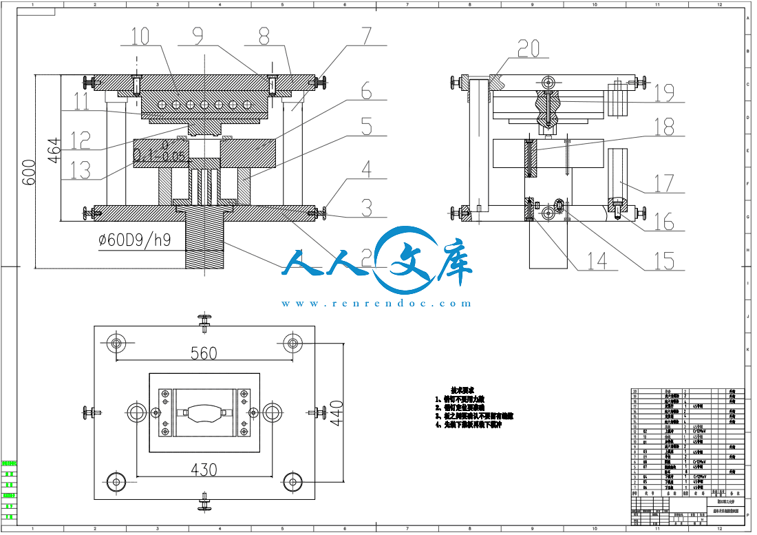
阴模固定块-Model.dwg
阴模固定块-Model.dwg

汽车刹车片模具设计【任务+开题+文献综述】【11张CAD图纸】【优秀】

收藏

资源目录
跳过导航链接。
汽车刹车片模具设计【任务+开题+文献综述】【11张CAD图纸】【优秀】.rar
压缩包内文档预览:
预览图
编号:275457    类型:共享资源    大小:12.83MB    格式:RAR    上传时间:2014-05-13 上传人:上*** IP属地:江苏
49
积分
关 键 词:
汽车 刹车片 模具设计 任务 开题 文献 综述 cad图纸
资源描述:

汽车刹车片模具设计

33页 15000字数+说明书+任务书+开题报告+文献综述+11张CAD图纸

A0装配图-Modeldwg

PDF图纸版

PDF资料

上模冲-Modeldwg

上模座-Modeldwg

下推板-Modeldwg

下模冲-Modeldwg

下模座-Modeldwg

任务书doc

加热板-Modeldwg

垫板-Modeldwg

导柱-A4dwg

文献综述doc

汽车刹车片模具设计开题报告doc

汽车刹车片模具设计论文doc

电子表格

阴模1-Modeldwg

阴模固定块-Modeldwg


摘要

粉末冶金是一种不需要将材料融化的冶金方法,是冶金和材料科学的一个分

支。而随着经济的发展,粉末冶金工艺具有生产效率高、质量稳定、成本低以及

可加工复杂形状工件等一系列优点,使其在现代工业中的地位也越来越高。相应

的,粉末冶金模具作为现代高速成型技术在工艺装备中起到越来越大的作用。特

别是在汽车行业中应用的比例越来越重,是现代汽车行业发展的重要支柱之一,

现代工业发展的一个方向

本次设计了一套汽车刹车片的压制模。本课题主要是查找刹车片的压坯到模

具模架的选择准则,了解各个零件的具体要求。从对零件压坯的尺寸,密度,质

量和高度等计算,来确定阴模与模冲的类型,再通过对压机的选择设计所需要的

模具,顶出方式的选择,加热方式的选择,加热元件规格的计算与选择,对模具的

材料进行选择,强度校核,粗糙度的确定,最后画出零件图和装配图。

关键字:粉末冶金;压制成形;刹车片模具Powder metallurgy is a branch of metallurgy

and materials science who is aneconomy,Because of powder metallurgy process with high efficiency, stable quality,

low cost and can be processed with complicated shapes advantages,so that it’s

position in modern industry are more and more important Accordingly, powder

metallurgy die as a modern high-speed molding technology play an increasingly

important tole in the process equipmentEspecially in the automotive industry, an

increasing proportion of re-application,is one of the important pillars of the modern

automobile industry and also is a direction of Modern industrial development

This design is a press die of brake padsThe project must basis on part’s size,

densit, height and mass to design the mild’s stamping typeThen basis on press

machine to choice mold’s type Then I choice the best way for pushing-out and

boiling Next step are Selecting the material of the mold and Strength check The last

way, I must determine the roughness and draw the parts and assembly drawings

finally

摘要

Abstract

第 1 章 绪论 1

11 粉末冶金概述 1

12 模具工业在现代工业国民经济中的地位 4

13 粉末冶金模具的现状 4

第 2 章 粉末冶金模具设计的原则 5

21 通用粉末成形压机的选择原则 5

22 压坯的选用原则 5

23 压制成形模具设计准则 6

第 3 章 模具的设计和材料选择 6

31 压坯的要求和压制方式的选择 6

311 压制方式的选择 9

312 顶出方式的决定 11

313 加热管的排布方案与选择 12

32 阴模的设计 13

33 上下模冲的设计 13

331 下模冲长度的设计 13

332 上模冲的设计 14

34 其它模架零件的设计 14

35 连接方式的设计 15

351 上下模座与固定板之间的连接 15

352 下模座与阴模固定板之间的连接 15

36 阴模材料的选择 15

37 模冲材料的选择 16

38 模架的材料选择 16

第 4 章 强度的校核 17

41 压机的选择 17

42 模冲强度校核 17

第 5 章 模具间的余量的计算 18

51 下模冲的弹性变形余量 18

52 阴模与下模冲的间隙 18

53 压坯烧结率与回弹率的总收缩率计算 19

531 压坯的回弹率 19

532 回弹率的影响因素 20

533 烧结收缩率 20

第 6 章 主要零件加工后应达到的要求21

61 阴模21

62 模冲22

63 其他零件 22

汽车刹车片模具设计

总结与展望 24

参考文献27

致谢 29

压坯密度的均匀性,是大压模设计要解决的主要压制质量指标。

在压制过程中,影响压坯密度分布均匀的因素较多,除了粉末成分、性能及模

具表面质量外,主要有两个方面:一是由于模壁之间的摩擦所引起的压坯密度不

均匀分布,他于压制方式有关。二是当模腔中的粉末同时受到压缩式,粉末体产

生柱式流动,几乎不产生明显的横向流动,所以压坯密度分布均匀性还与模腔内

各部分粉末填装高度、压缩比、压缩速率或最后压缩速度有关,这些都可以通过

压制工艺参数来控制。

由于粉末与模壁之间的摩擦,所引起压坯密度无论是在高度还是横截面的分布

都是不均匀的,特别是随着压坯高径比的增大引起的压坯密度沿高度方向的不均

匀越来越大。但是压制方式的不同,压坯密度分布有很大差别。

单向压制时,压坯密度分布很不均匀,如果采用双向压制中的非同时双向压制

或摩擦芯杆压制,可以显著改善压坯密度分布的不均匀性。

明确了压坯密度分布与压制方式之间的关系后,要解决压模设计中压坯密度分

布的均匀性,必须根据压坯的形状、高径比、生产批量和压机选择压制方式和压

模结构类型。

内容简介:
1附件二:浙江理工大学本科毕业设计(论文)任务书赵天星同学(专业 / 班级:09 机械设计制造及其自动化(4)班)现下达毕业设计(论文)课题任务书,望能保质保量地认真按时完成。课题名称课题名称汽车刹车片模具设计主要任务主要任务与与目标目标1)汽车刹车片成形方案设计分析汽车刹车片的结构特点、尺寸精度,利用 CAD 和 Pro/E绘制二维图、三维图,最终确定汽车刹车片的工艺成型方案和模具结构设计;2)根据汽车刹车片的工艺方案,结合汽车刹车片的公差等级、制作模具的成本、精度要求和生产效率等因素,确定模具总体结构形式,完成模具的结构设计。3)零件设计和相关计算;目标:得出相关二维零件图,装配图,三维零件,装配图,仿真相关动画及相关分析图,写出设计论文。主要内容主要内容与基本要与基本要求求主要设计内容有:1)测绘模型零件,并绘制零件的二维图和三维造型;2)用 pro/e 软件对制件进行成形工艺性分析,确定最佳成形工艺方案;3)冲压模具设计,完成三维、二维图纸;基本要求:零件三维造型结构合理,连接位置的形状和尺寸正确,能够进行装配,完成注塑模具的总体结构方案,完成三维、二维装配图和零件图,总计不少于 5 张图纸;完成毕业设计要求的各种文档,包括文献综述、开题报告、外文翻译及毕业设计论文等。严格按照进度安排,保质保量完成所承担的任务;遵守实验室规定。2主要参考主要参考资料及文资料及文献阅读任献阅读任务务1 牟红霞模具材料的发展与动向现代制造技术与装备,2006,4:83842刘全坤,王成勇,刘传经模具技术的现状与未来发展重点模具工业,2011,37(5)143马超,浅谈我国冲压模具的发展趋势,2012,35;4孔炎,梁辰。赵蒙,聂爱琴,汽车端盖零件的冲压模具设计,文章编号:16746457(2012)060129035 洪慎章,曾振鹏密封盖落料拉伸冲孔切边复合模设计J模具工业,2OOl(11):23266 郝滨海冲压模具简明设计手册(第 2 版)M北京:化学工业出社,2009:1944,1651827 朱家诚机械设计课程设计M合肥:合肥工业大学出版社,2005:2502518 周淑容冲裁间隙对冲裁件质量的影响及其选择方法J科技信息,2009(12):22259崔令江.汽车覆盖件冲压成形技术M.机械工业出版社,2003.10刘绪功.基于特征的汽车覆盖件冲压成形性研究D. 南京:南京航空航天大学,2005.11朱东波,王伊卿等.电弧喷涂汽车覆盖件冲压模具快速制造方法P.中国专利:03134500,2004.4.12程应潮,范国辉.国内外桥车覆盖件冲压模具设计概括.1672-0121(2004)04-0026-0413李体彬.冲压成型工艺. 化学工业出版社. 2008. 023458 号:119814李德群,肖祥芷.模具 CAD/CAE/CAM 的发展概况及趋势J.模具工业,2005(7) :9-1215中国模具工业协会.模具行业“十一五”规划J.模具工业,2005(7) :3-816李大鑫,张秀锦.模具技术现状与发展趋势综述J.模具制造,2005 (2) :1-417张春水. 国内外冷冲模技术现状及发展趋势,1991,第 1 期18Richard W.Sorenson . Push button switch with compound contac lever action.Ameica:4640998,1987-02-03.19王华,尚振国.Solid Works 在冲压模具设计中的应用,中国科技信息 2008 年,第 15期:141-142.20聂兰启,聂伯扬. 薄壁深锥零件的拉伸成形.模具制造 ,2008 年,第 8 期,29-32.21邓明,吕琳.冲压成形工艺及模具.第 1 版.北京:化学工业出版社,2006 年:117-125.322 ZHOU Li-Qun,LI Yu-Ping,ZHOU Yi-Chun.A Mechanics Model for Stamping a Sheeton Elastic Die with Large Deformation.Journal of Shanghai Uniwersity(EnglishEdition),2002,6(2):130-135.23彭建声.冷冲压技术问答(上册).第 3 版.北京:机械工业出版社,2006 年:336-340.外文外文翻译任务翻译任务阅读 10000 字符以上的外文文献, 并至少翻译 5000 汉字的两篇外文文献, 若一篇篇幅较长,则另一篇只需翻译开头部分。计划进度:计划进度:起止时间内容2013.2.12013.2.25前期资料准备、毕业设计任务书、文献综述、外文翻译布置。2013.2.252013.3.3查阅资料(包括外文资料),撰写文献综述、开题报告及外文资料翻译。2013.3.32013.3.8完成开题报告。开题报告答辩。2013.3.92013.4.5总体方案设计,分析计算,结构设计。2013.4.52013.4.12方案设计,分析计算,结构设计,图纸绘制,撰写说明书。2013.4.132013.4.18毕业设计中期检查完成情况及表格与记录的填写。2013.4.182013.5.10完成图纸绘制,说明书撰写。提交毕业设计(论文) 。2013.5.112013.5.18毕业设计(论文)的审阅;评议小组分组审阅。2013.5.192013.5.30毕业设计答辩。实习地实习地点点指导教师指导教师签签名名年月日系系 意意见见系主任签名:年月日学院学院盖章盖章主管院长签名:年月日AFew Pointers for Picking a Best Stamping DieIt makes sense to stamp parts instead of machine them whenproduction volumes are high and machining the parts would requiremultiple secondary operations.Good candidates for stamping includeparts such as ball-bearing retainers,grid cups for cathode-ray tubes,andpotentiometer and circuit-breaker components.These can be made frommaterials including aluminum,exotic metals,cold rolled and stainlesssteel,and red metals such as copper,brass,beryllium copper,phosphorbronze.Process options involve traditional power presses with progressivedies,multislidepressesrunningmultislidetooling,orindependent-cam-operatedplungerpresseswitheyelet-transfertooling.Selecting the correct process is criticalfor balancing economy andpart quality.Here are a fewconsiderations to help select a stampingmethod.Progressive dies produce finished flat,formed,anddrawn parts bycombining several operations in one die.A strip of flat metal enters the dieand is fed through one station at a time.Each station forms or cuts aparticular feature such as a bend,notch,or hole.When the strip reaches thelast station,the parts are complete and the tool cuts them free from thestrip.One drawback:remaining scrap can reach up to 50%.Anycombinationofoperationssuchasnotching,forming,coining,tapping,and assembly can be designed into a progressive die aslong as the part configurations and tolerances remain acceptable.Ourcompany stamps materials asthick as 0.1875-in.with this method. But keep in mind its sometimesnecessary to perform acritical dimension that would otherwise be difficultto control in a die.And for low production quantities,it often makes senseto exclude a station because of tooling complexity.In these cases,finishingparts in a secondary operation makes sense,even though it involves morelabor.It may also be necessary to exclude stations such as complexcam-actuated stations or those performing in-die tapping that require a lotof space because the die might become too long for the available presses.Multislide tooling is a good choice for complex parts with extensivebending operations that would be difficult to perform in a progressivedie.Multislide tooling is also good when parts are too costly to produce insingle-station hand-fed tooling,or call for cam-actuated stations.Themultislideprocessinvolvesformingtoolsmovingfrommultipledirections.Multislide tooling is less expensive and it produces parts withlittle or no scrap,a significant factor with high volumes and special metals.Multislide machines can accommodate progressive dies to pierceholes,notches,or perform other operations before reaching the formingtools.Production pricing is about the same for complex parts that couldtypicallybemadecompleteineitherprogressiveormultislidetooling.Variables include material usage and run rate.Our companyprocesses material up to 0.125-in.thick and 2-in.wide with a multislidemethod. Eyelet-transfer tooling is primarily for deep-drawn parts.Theseare transferred from station to station byfingers, instead of a carrierstrip as with progressive dies.This saves considerable raw material.Also,process control is greaterbecause each station is independent.Its even possible to account forsubtle changes in material properties to better maintain tolerances.Punches in an eyelet machine are independently adjustable, whileprogressive-die punches are more difficult to adjust because they aremounted to a common holder. Depending on the part complexity and thenumber of stations required,the eyelet-transfer method produces afinished part that requires no secondary operations.In fact,features such as side-pierced holes or notches, knife-edges,andcoined edges or surfaces that would normally have required secondarypress operations can be incorporated into the tooling.The only limitationsare part size and complexity,material thickness,and the number of stationsavailable in the press. Eyelet tooling shines in adaptability.Toolingmodifications from a revised part are less costly than with the othermethods.This is particularly true when parts have the same shapes,butvary in size.Its easier to share tooling and produce only the necessaryadditional tooling.The eyelettransfer method lets our company produceparts having a maximum depth and O.D.of 1.5 in.对于选取一个最好的冲压模具的一些指点当零件产量过高时有效的减少辅助操作的步骤是非常有意义的。 一个好的冲压模具的选择连零件也包含在内, 比如球轴承保持架,用于阴极射线管,和电位器和断路器组件的网格杯。制作的材料包括铝,特殊金属,冷轧和不锈钢,和红色的金属,如铜,黄铜,铍铜,磷青铜等。工序的选择包括传统的动力压力机进模,多边滑落压力机运行的多边滑落工具,或拥有独立的孔传输工具的凸轮式柱塞压力机。选择正确的流程是关键为平衡经济和零件质量。 这里有几个考虑到帮助选择冲压的方法。渐进式模具生产平收,形成和拉深部件将多个操作组合在一个模具中。进料和到达的站点是在同一时间。 每个站形成或削减特定工艺,如一个弯曲,凹口或孔。当带材达到的最后一站,零件是完整的和工具切割它们摆脱带材。有一个缺点就是边角料的剩余可能达到50%。任意组合的操作,如开槽,形成压印,攻丝和组件可以设计成一个只要进模的配置和公差仍然可以接受。 用这种方法我们的公司印章材料厚为0.1875。但请记住,有时需要执行大概的尺寸,否则在模具中将难以控制。低生产量时,因为模具的复杂性,往往由于错我的感应而排除一站。在这些情况下,在二次操作整理零件的意义上说, 将使它涉及更多的劳动。 它也可能是需要排除站,如复杂的凸轮驱动站或需要模具内部攻丝的特定的空间, 因为可能会变得太长为可用的压力机。 多边滑落工具是一个不错的选择复杂的零件具有丰富的弯曲操作性,这将困难的进模执行程序变得可行。多边滑落工具也是良好的选择,当零件的成本太高,生产用单站式人工式送料工具,或拨打凸轮驱动站。从多个方面来说,多边落料过程涉及的成型工具,更加便宜,而且废料很少或根本没有废料,大批量生产和特种的材料应用就是一个明显的因素。 多边落料机可以在模具中加工穿孔,缺口或执行其他操作之前完成工具成型,在进行复杂的零件加工时完成渐进式或需要多边落料的工具时, 它的生产价格也是一样的。可控的变量包括材料的使用和运行速度。我们公司流程材料厚0.125,宽2。圆头传输工具主要作为深冲部件。 这种一站接一站的 “手指”,用来代替进模的一种载体带钢。这种方法极大地节省了原料的损耗。除此之外,在每个过程中的控制都是独立的。更加完美的是,它甚至为了更好的维护公差而考虑到了材料性能的微妙变化。 凸模在小孔机器上式独立可调的,而渐进式多模冲头的调整却是很困难的,因为它们被安装在同一个支架上。 由此根据零件的复杂性和必须的工作站数量, 圆孔传输的生产方法是它已经完成的一部分, 并不需要二次操作。事实上,该机器的功能特点,比如在侧面钻孔或者凹口,在车刀的边缘制作一种边缘或者表面,通常需要二次操作,从而制造出一种合适的工具。唯一的局限就是零件的大小和复杂性,材料的厚度,以及有限的压力机。圆头工具让人眼前一亮的地方就是它的超强的适应性。模具修改的零件部分与其它方法相比成本是很低的。 当在加工相同的部件时,形状是完全一样的,指引大小的不同而有所差异。再加工模具和生产时,它更容易装载其他额外的配套工具。该圆头传输的加工方法可以使该公司生产的零件的最大加工深度到O.D.1.5英寸。Hot Stamping Die Design for Vehicle Door Beams using Ultra-HighStrength SteelChao Jiang, Zhongde Shan, Bailiang Zhuang, Milan Zhang, andYing XuKEYWORDS: :Hotforming,Ultra-highstrengthsteel,Mechanicalcharacteristics,Automobile lightweightThe energy saving and safety is the eternal theme of development ofautomobile industry. Ultra-high strength steel automotive body structuresof hot stamping have been widely used with these dual advantages thatreducing vehicle weight while enhancing safety performance at the sametime. The forming and quenching integration die was investigated in thispaper with a vehicle door beam as an example, especially the whole diestructure and hot stamping process were optimized through numericalsimulation of die strength, cooling pipe arrangement and other relatedfactors, and beam samples with tensile strength 1550Mpa, elongation rate6.5% and shape accuracy of 0.3mm were produced by this die.Moreover, the stiffness increased by 2.2 times than the original tube beamand 3.8 times of the intensity, which led to full score in C-NCAP CrashTest. By reducing the thickness cross section and the depth of drawingcomparing with the original tubular beam, door beam weight could bereducedby9.32%,whichhadeffectiveenergy-savingandemission-reduction effect.1. IntroductionLight weight auto-body and passive safety of passengers become trendof automotive industry, while energy saving and environment protectingdeeply wised. Application ofultra-high strengthsteel with dualadvantages of weight-light and safety improvement performance growsrapidly, also with characteristics of both high-strength and high-precision,has become a industry hotspot.On one hand, the forming process parameters are the key points of hotstamping technology, on the other hand, hot stamping die needs to setcooling system to ensure the die function of stamping and quenching,which is quite different from the common stamping mold. The mainparameters including heating temperature, holding time, forming speed,impulse pressure, holding time, open mold temperature, flow velocity andetc., should be optimized during hot stamping process primarily forguaranteed high-intensity and highprecision of forming parts. Taking aChinese independent brand car door beam as an example, ultra-highstrength steel hot stamping technology and lightweight design werestudied in this paper.1-32. Development of hot stamping die for ultra-highstrength steel door beam2.1 Material optimization of hot stamping dieDuring hot stamping process, phase transformation strengthening ofparts after forming is completed through the dies, so the dies requirecreation of cooling pipes inside to realize a cooling quenchingfunction.4,5 From the point of view for material properties, die materialmust have high thermal conductivity coefficient in order to achieve rapidand uniform cooling effect, better thermal fatigue performance and highheat strength to work under long-term alternation of heating and coolingstate, strong wear-resistance to bear thermal friction of high temperatureblank and its oxidation skin.6-8Hot working die steel material of HHD containing high chromium inthe composition (shown in Table 1) to enhance its corrosion-resistancewas used. Under normal temperature, the Table 1 Composition of HHD(wt-%)CCrMoNiVWSiMn0.20.358.013.01.02.01.00.31.01.0hardness of HHD was above HRC48, which could keep as HV 498.2 at600, showing high strength and good thermal stability at hightemperature. And the material sh ows excellent wear-resistance at hightemperature, which is less than a third of that ofASSAB8407.2.2 Development of ultra-high strength steel door beam andstamping die cooling systemTubular beam including seamless tube and seam is a kind of door beam,among which the seam welded pipes with a maximum tensile strength ofabout 400MPa were manufactured by welding steel plates after beingbent into pipes, and seamless steel pipes manufactured by drawingprocess had the tensile strength up to 600MPa, rare hardened tube got atensile strength of 1400MPa. These door beams had simple structure andlow manufacture cost, but relatively poor protection performance.Another kind of anticollision door beam known as hat-shape beam wasmainly divided into single-cap shape (U-type) and double-hat shape(W-type), whose tensile strength could reach above 1500MPa and gethigher safety performance through hot stamping process, more widelyused in European andAmerican cars.Adoor beam was optimized from seamless pipe to two-hatshape (thickness of 2mm, length of 1071mm, and width of 99.9mm)with the following shape shown in Fig. 1.Cooling pipes were arranged in even distribution to maintaingood cooling efficiency, as shown in Fig. 2, bolt seal methodWas used on the end of die and O-shape sealing rings were used at thebottom to prevent leakage of high-speed cooling water circulation.Thecooling rate was guaranteed by water velocity regulated according toproduction cycle, and the appropriate temperature of cooling water wasselected.9,102.3 Design of cooling parametersCooling system of hot stamping die influences not only the completionof forming and quenching but also final properties of the parts. Theparameters include such three aspects as depth from die surface tocooling pipe, spacing between pipes (pipe center distance) and thediameter of cooling pipe, that is, location, arrangement and pipe shape.Pre-condition for a numerical simulation as initial die temperature of20, initial blank temperature of 890, cooling water flow rate of 1m/s,and other cooling parameters are given in Table 2. The simulation resultswere shown in Fig. 3.As shown in Fig. 3, with increasing of depth from die surface tocooling pipe and space between pipes, the average cooling rate decreases;with increasing of pipe diameter, the average cooling rate linearlyincreases. And the greatest influence factor on cooling effectiveness isdepth of pipe from the surface, followed by pipe spacing, and finally pipediameter, that is, calculative determination of depth from die surface tocooling pipe should be considered first during design of die coolingsystem, and it is also the basis of the reasonable design of pipe spacingand pipe diameter. The depth from die surface to cooling pipe of 10mm,pipe spacing of 15mm and pipe diameter of 10mm was the optimizedresult of the Simulation. The design of cooling pipe should make sure thatthe die could keep ensuring sufficient strength during hot stampingprocess, so the overall strength intensity of the die needs to be checkedfirstly. The next numerical simulation boundary conditions were asfriction coefficient of 0.03, forming speed of 50mm/s, the stress field andforce were shown in Fig. 4.The results showed that there was no damage on die because themaximum deformation was only 0.027mm, which was in the elasticdeformation range. The stress simulation results showed that the stress isfar less than that of the blank mechanical strength, cracking phenomenawould not happen. The corresponding door beam die entities was shownin Fig. 5.超高强度钢在车辆门梁热冲压模具设计中的应用关键字:热成型,超高强度钢,机械特性,汽车轻量化纵观汽车的发展,节能和安全可靠性是它永恒的主题。由于超高强度钢既可以降低车身的重量并且大大的提高安全可靠性这双重优点,它已经被广泛的应用在热冲压车身结构中。在这些研究中, 以汽车门梁的热冲压模具作为一个例子, 特别是通过数值模拟模具的强度来对整个模具结构和热冲压工艺进行优化。 而冷却管和其他相关的因素,以及梁的平均抗拉强度为 1550MP,伸长率 6.5%和+-0.3mm 的形状精度,以此来确定该如何生产该模具。除此之外,该零件的刚度比原来材料的管梁强度提高了 2.2 倍和 3.8 倍,这是在 C-NCPA 碰撞试验中得来的。通过减少横截面的厚度和深度的比较,试验样本比原来的管状梁的重量可以减少 9.32%,其中节能减排的效果显著。1.导论汽车车身轻量化, 更加注重乘客的被动安全性已经成为了汽车行业发展的趋势,而与此同时节约能源和环
温馨提示:
1: 本站所有资源如无特殊说明,都需要本地电脑安装OFFICE2007和PDF阅读器。图纸软件为CAD,CAXA,PROE,UG,SolidWorks等.压缩文件请下载最新的WinRAR软件解压。
2: 本站的文档不包含任何第三方提供的附件图纸等,如果需要附件,请联系上传者。文件的所有权益归上传用户所有。
3.本站RAR压缩包中若带图纸,网页内容里面会有图纸预览,若没有图纸预览就没有图纸。
4. 未经权益所有人同意不得将文件中的内容挪作商业或盈利用途。
5. 人人文库网仅提供信息存储空间,仅对用户上传内容的表现方式做保护处理,对用户上传分享的文档内容本身不做任何修改或编辑,并不能对任何下载内容负责。
6. 下载文件中如有侵权或不适当内容,请与我们联系,我们立即纠正。
7. 本站不保证下载资源的准确性、安全性和完整性, 同时也不承担用户因使用这些下载资源对自己和他人造成任何形式的伤害或损失。
提示  人人文库网所有资源均是用户自行上传分享,仅供网友学习交流,未经上传用户书面授权,请勿作他用。
关于本文
本文标题:汽车刹车片模具设计【任务+开题+文献综述】【11张CAD图纸】【优秀】
链接地址:https://www.renrendoc.com/p-275457.html

官方联系方式

2:不支持迅雷下载,请使用浏览器下载   
3:不支持QQ浏览器下载,请用其他浏览器   
4:下载后的文档和图纸-无水印   
5:文档经过压缩,下载后原文更清晰   
关于我们 - 网站声明 - 网站地图 - 资源地图 - 友情链接 - 网站客服 - 联系我们

网站客服QQ:2881952447     

copyright@ 2020-2024  renrendoc.com 人人文库版权所有   联系电话:400-852-1180

备案号:蜀ICP备2022000484号-2       经营许可证: 川B2-20220663       公网安备川公网安备: 51019002004831号

本站为文档C2C交易模式,即用户上传的文档直接被用户下载,本站只是中间服务平台,本站所有文档下载所得的收益归上传人(含作者)所有。人人文库网仅提供信息存储空间,仅对用户上传内容的表现方式做保护处理,对上载内容本身不做任何修改或编辑。若文档所含内容侵犯了您的版权或隐私,请立即通知人人文库网,我们立即给予删除!