镗套图.dwg
镗套图.dwg

车床尾架体加工方案与镗床Φ75孔夹具设计【卡片】【29张CAD图纸】

收藏

资源目录
跳过导航链接。
车床尾架体加工方案与镗床Φ75孔夹具设计【卡片】【29张CAD图纸】.rar
镗套图.dwg---(点击预览)
车床尾架体加工方案与镗床Φ75孔夹具设计说明书.doc---(点击预览)
机械加工工序卡片 - 90.dwg---(点击预览)
机械加工工序卡片 - 80.dwg---(点击预览)
机械加工工序卡片 - 70.dwg---(点击预览)
机械加工工序卡片 - 60.dwg---(点击预览)
机械加工工序卡片 - 50.dwg---(点击预览)
机械加工工序卡片 - 160.dwg---(点击预览)
机械加工工序卡片 - 150.dwg---(点击预览)
机械加工工序卡片 - 140.dwg---(点击预览)
机械加工工序卡片 - 120.dwg---(点击预览)
机械加工工序卡片 - 110.dwg---(点击预览)
机械加工工序卡片 - 100.dwg---(点击预览)
支架图零件图.dwg---(点击预览)
底座零件图.dwg---(点击预览)
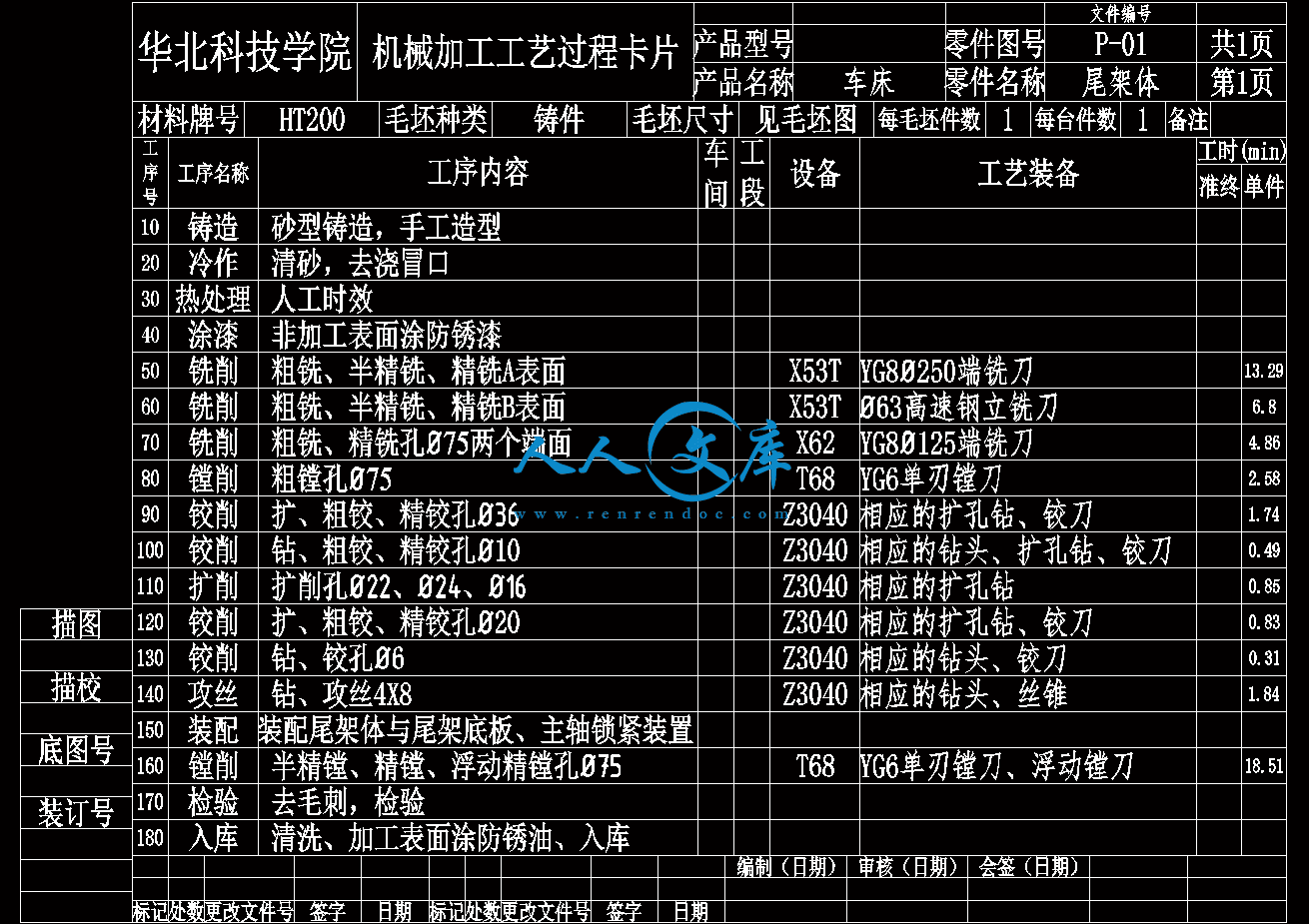
工艺过程卡.dwg---(点击预览)
山型定位板零件图.dwg---(点击预览)
夹具装配图.dwg---(点击预览)
外文翻译--机械设计.doc---(点击预览)
吊环螺栓三视图.dwg---(点击预览)
2机械加工工序卡片 - 90.dwg---(点击预览)
2机械加工工序卡片 - 80.dwg---(点击预览)
2机械加工工序卡片 - 70.dwg---(点击预览)
2机械加工工序卡片 - 60.dwg---(点击预览)
2机械加工工序卡片 - 50.dwg---(点击预览)
2机械加工工序卡片 - 160.dwg---(点击预览)
2机械加工工序卡片 - 150.dwg---(点击预览)
2机械加工工序卡片 - 140.dwg---(点击预览)
2机械加工工序卡片 - 120.dwg---(点击预览)
2机械加工工序卡片 - 110.dwg---(点击预览)
2机械加工工序卡片 - 100.dwg---(点击预览)
压缩包内文档预览:
预览图
编号:283173    类型:共享资源    大小:1.42MB    格式:RAR    上传时间:2014-05-17 上传人:上*** IP属地:江苏
40
积分
关 键 词:
车床 尾架体 加工方案 镗床Φ75孔 夹具 设计卡片 cad图纸
资源描述:

车床尾架体加工方案与镗床Φ75孔夹具设计

79页 31000字数+说明书+工艺过程卡+机械加工工序卡片+29张CAD图纸

吊环螺栓三视图.dwg

外文翻译--机械设计.doc

夹具装配图.dwg

山型定位板零件图.dwg

工艺过程卡.dwg

底座零件图.dwg

支架图零件图.dwg

机械加工工序卡片 - 100.dwg

机械加工工序卡片 - 110.dwg

机械加工工序卡片 - 120.dwg

机械加工工序卡片 - 140.dwg

机械加工工序卡片 - 150.dwg

机械加工工序卡片 - 160.dwg

机械加工工序卡片 - 50.dwg

机械加工工序卡片 - 60.dwg

机械加工工序卡片 - 70.dwg

机械加工工序卡片 - 80.dwg

机械加工工序卡片 - 90.dwg

车床尾架体加工方案与镗床Φ75孔夹具设计说明书.doc

镗套图.dwg

车床尾架体加工方案与镗床Φ75孔夹具设计

2机械加工工序卡片 - 100.dwg

2机械加工工序卡片 - 110.dwg

2机械加工工序卡片 - 120.dwg

2机械加工工序卡片 - 140.dwg

2机械加工工序卡片 - 150.dwg

2机械加工工序卡片 - 160.dwg

2机械加工工序卡片 - 50.dwg

2机械加工工序卡片 - 60.dwg

2机械加工工序卡片 - 70.dwg

2机械加工工序卡片 - 80.dwg

2机械加工工序卡片 - 90.dwg

目录

摘要1

Abstract2

1 绪论3

2 零件分析4

2.1 零件的作用4

2.2 零件外形的特点4

2.3 零件的主要技术特点4

2.4 零件的工艺分析4

2.5 确定零件的主要加工表面5

3 机械加工工艺规程的设计6

3.1零件毛坯的确定6

3.1.1 毛坯种类选择6

3.1.2 确定毛坯的加工余量6

3.2 机械加工路线的拟定7

3.2.1 选择零件表面的加工方法7

3.2.2 工序定位基准的选择9

3.2.3 工序数目和顺序的确定9

3.2.4 确定工序间的加工余量和工序尺寸及其公差12

3.3 机床和工艺装备的选择和设计18

3.3.1机床的选择18

3.3.2刀具的选择18

3.3.3量具的选择18

3.3.4夹具的选择和设计19

3.4 切削用量的选择19

3.4.1背吃刀量的选择19

3.4.2进给量f的选择19

3.4.3切削速度的选择20

3.4.5各加工表面的切削用量的选择20

3.5工时定额的估算57

3.5.1 工时定额57

3.5.2 工时定额的组成57

3.5.3各工序单件时间的计算58

3.6填写机械加工工艺文件63

3.6.1机械加工工艺过程卡片63

3.6.2机械加工工序卡片63

3.6.3检验卡片63

4 专用夹具的设计64

4.1 定位基准和定位元件的选定64

4.1.1 合理定位基准的选择64

4.1.2定位元件的选择65

4.2 镗套的选择和设计66

4.2.1 导向装置的形式与特点66

4.2.2镗套的材料66

4.3镗杆的设计67

4.3.1镗杆的结构67

4.3.2镗杆端部导向结构形式67

4.4.3 镗刀与镗刀孔的结构67

4.3.4 镗杆的尺寸68

4.3.5镗杆的材料69

4.3.6镗杆与机床主轴的连接方法69

4.3.7镗套结构的修正69

4.4夹紧装置的设计71

4.4.1夹紧装置的组成71

4.4.2对夹紧装置的要求72

4.5夹紧力的确定73

4. 6夹具体的设计77

5 结论79

参考文献80

致谢81

外文科技资料翻译82

英文原文82

中文译文88

摘要

本课题主要是某机床尾架体的加工工艺及夹具的设计,在设计中先设计该尾架体的加工工艺,再根据加工工艺来设计镗床夹具。由于孔75的精度要求高和定位尺寸误差小,为保证孔的位置和加工准确性我们在加工底面的时候通过画线找正的方法确定底面的加工余量,这样就可以更好的保证孔75的位置精度。加工孔75的时候为保证相对于A面和B面的平行度和垂直度公差,我们就得要准确地设计出以A和B面为定位基准的夹具。还考虑到工件的圆度和圆柱度的误差小,设计夹具要考虑加工时候的震动,为减少震动,那就得在孔75的附近找个夹紧点。2 零件分析

在进行零件加工工艺设计前,必须认真研究被加工零件图样,从加工制造的角度分析研究零件的结构、尺寸、形状、硬度、质量、尺寸精度、形位精度、表面粗糙度和材料及热处理方面的技术要求,明确技术条件的制订依据,从而为制订合理的工艺规程与专用设备设计作好必要的准备。

2.1 零件的作用

题目所给的零件是车床尾架体,尾架安装在车床的右端导轨上,尾架上的套筒可以安装顶尖,以支承较长的工件的右端(即顶持工件的中心孔)、安装钻头、铰刀,进行孔加工,也可以安装丝锥攻螺纹工具、圆析牙套螺纹工具加工内、外螺纹。尾架可以沿尾架导轨作纵向调整移动,然后压下尾架紧固手轮将尾架夹紧在所需位置,摇动尾架手轮可以实现对工件的顶紧、松开或对工件进行切削的纵向进给。

2.2 零件外形的特点

该零件属于异形零件,加工过程中主要考虑工件的装夹定位与加工变形的问题。

2.3 零件的主要技术特点

(1)零件的材料是HT200,该材料为灰铸铁,具有较高的强度,耐磨性,耐热性及减振性,适用于承受较大应力和要求耐磨的零件。由于HT200的铸造应力比较大,故铸件需进行人工时效处理;

(2)孔75H6要求圆度为0.015;

(3)孔75H6要求圆柱度为0.015;

(4)孔75H6与A表面的平行度要求为0.04;

(5)孔75H6与B表面的垂直度要求为0.03;

(6)A表面要求平面度为0.025;

(7)各加工表面达到尺寸精度和表面粗糙度的要求。

2.4 零件的工艺分析

(1)零件的材料是灰铸铁,具有良好的金属切削加工性;

(2)零件主要进行孔加工和平面加工,钻孔及攻丝;

(3)零件的A、B两基准平面精度要求较高,与尾架主轴孔之间的相互位置精度要求也较高;

(4)零件主轴孔有两处按装配要求进行加工:一是应与尾架底板装配后再镗孔,二是应与尾架主轴锁紧装置装配后再镗孔;

(5)尾架主轴孔有较高的尺寸精度和形状位置精度要求,加工难度大。毛坯制造是零件生产过程的一部分,零件所用的毛坯选择是否合适,将影响工艺过程是否优质、高产和低消耗。正确选择毛坯主要应考虑以下几个因素:

(1)零件的材料及力学性能;

(2)零件的结构形状和尺寸大小;

(3)零件的生产批量和精度要求;

(4)工厂毛坯车间的现有设备和技术水平。

由于零件外形比较复杂,只能采用铸造的方法生产毛坯。生产批量为中批生产,采用砂型铸造,手工造型。铸造后,铸件需要消除毛刺和砂粒,并作退火处理。

3.1.2 确定毛坯的加工余量

合理的加工余量,对确保加工质量、提高生产率和降低成本都有重要的意义。加工余量过小,不能完全切除上工序留在加工表面上的缺陷层和各种误差,也不能补偿本工序加工时工件的装夹误差;加工余量过大,不仅增加了机械加工量,降低了生产效率,而且浪费原材料和能源,增加刀具的损耗,使加工成本升高。

确定毛坯加工余量的基本原则是:在保证加工精度的前提下,尽量减少加工余量,以提高生产率。目前一般采用经验估计法和查表法来具体确定余量值,并就考虑下列几条原则:

(1)零件尺寸精度或表面粗糙度要求高的加工表面,应有较大的加工余量;

(2)加工面积大的表面加工余量应加大;

距基准较远的加工表面,加工余量就加大;

(4)出现缺陷或开设浇冒口的位置应留工艺余量。

下面采用查表法确定各加工表面的加工余量:

查表2-1 大中批量生产的毛坯铸件的公差等级和表2-5 毛坯铸件典型的机械加工余量(邹[ 见参考文献2])等级得,对于铸件材料为灰铸铁,采用砂型铸造的铸件,其尺寸公差等级CT为8~10级,加工加工余量等级RMA为E~G级,故取CT=10,RMA=G。

查表2-3 铸件尺寸公差和表2-4 要求的铸件机械加工余量(RMA)(邹)确定各加工表面的总余量下表:


内容简介:
华北科技学院毕业设计(论文)外文科技资料翻译英文原文LATHES The basic machines that are designed primarily to do turning, facing and boring are called lathes. Very little turning is done on other types of machine tools, and nine can do it with equal facility. Because lathe can do boring, facing, drilling, and reaming in addition to turning, their versatility permits several operations to be performed with a single setup of the workpiece. This accounts for the fact that lathes of various types are more widely used in manufacturing than any other machine tool. Lathes in various forms have existed for more than two thousand years. Modem lathes date from about 1797, when Henry Maudsley developed one with a leadscrew. It provided controlled, mechanical feed of the tool. This ingenious Englishman also developed a change-gear system that could connect the motions of the spindle and leadscrew and thus enable threads to be cut. The essential components of a lathe are are the bed, headstock assembly, tailstock assembly, carriage assembly, quick-change gear box, and the leadscrew and feed rod. The bed is the backbone of a lathe. It is usually made of well-normalized or aged gray or nodular cast iron and provides a heavy, rigid frame on which all the other basic components are mounted. Two sets of parallel, longitudinal ways, inner and outer, are contained on the bed, usually on the upper side. Some makers use an inverted V-shape for all four ways, whereas others utilize one inverted V and one flat way in one or both sets. Because several other components are mounted and/or move on the ways they must be made with precision to assure accuracy of alignment. Similarly, proper precaution should be taken in operating a lathe to assure that the ways are not damaged. Any inaccuracy in them usually means that the accuracy of the entire lathe is destroyed. The ways on most modern lathes are surface hardened to offer greater resistance to wear and abrasion. The headstock is mounted in a fixed position on the inner ways at one end of the lathe bed. It provides a powered means of rotating the work at various speeds. It consists, essentially, of a hollow spindle, mounted in accurate bearings, and a set of transmission gearssimilar to a truck transmissionthrough which the spindle can be rotated at a number of speeds. Most lathes provide from eight to eighteen speeds, usually in a geometric ratio, and on modern lathes all the speeds can be obtained merely by moving from two to four levers. An increasing trend is to provide a continuously variable speed range through electrical or mechanical drives. Because the accuracy of a lathe is greatly dependent on the spindle, it is of heavy construction and mounted in heavy bearings, usually preloaded tapered roller or ball types. A longitudinal hole extends through the spindle so that long bar stock can be fed through it. The size of this hole is an important size dimension of a lathe because it determines the maximum size of bar stock that can be machined when the material must be fed through the spindle. The inner end of the spindle protrudes from the gear box and contains a means for mounting various types of chucks, face plates, and dog plates on it. Whereas small lathes often employ a threaded section to which the chucks are screwed, most large lathes utilize either cam-lock or key-drive taper noses. These provide a large-diameter taper that assures the accurate alignment of the chuck, and a mechanism that permits the chuck or face plate to be locked or unlocked in position without the necessity of having to rotate these heavy attachments. Power is supplied to the spindle by means of an electric motor through a V-belt or silent-chain drive. Most modern lathes have motors of from 5 to 15 horsepower to provide adequate power for carbide and ceramic tools at their high cutting speeds. The tailstock assembly consists, essentially, of three parts. A lower casting fits on the inner ways of the bed and can slide longitudinally thereon, with a means for clamping the entire assembly in any desired location. An upper casting fits on the lower one and can be moved transversely upon it on some type of keyed ways. This transverse motion permits aligning the tailstock and headstock spindles and provides a method of turning tapers. The third major component of the assembly is the tailstock quill. This is a hollow steel cylinder, usually about 2 to 3 inches in diameter, that can be moved several inches longitudinally in and out of the upper casting by means of a handwheel and screw. The open end of the quill hole terminates in a Morse taper in which a lathe center, or various tools such as drills, can be held. A graduated scale, several inches in length, usually is engraved on the outside of the quill to aid in controlling its motion in and out of the upper casting. A locking device permits clamping the quill in any desired position. The carriage assembly provides the means for mounting and moving cutting tools. The carriage is a relatively flat H-shaped casting that rests and moves on the outer set of ways on the bed. The transverse bar of the carriage contains ways on which the cross slide is mounted and can be moved by means of a feed screw that is controlled by a small handwheel and a graduated dial. Through the cross slide a means is provided for moving the lathe tool in the direction normal to the axis of rotation of the work. On most lathes the tool post actually is mounted on a compound rest. This consists of a base, which is mounted on the cross slide so that it can be pivoted about a vertical axis, and an upper casting. The upper casting is mounted on ways on this base so that it can be moved back and forth and controlled by means of a short lead screw operated by a handwheel and a calibrated dial. Manual and powered motion for the carriage, and powered motion for the cross slide, is provided by mechanisms within the apron, attached to the front of the carriage. Manual movement of the carriage along the bed is effected by turning a handwheel on the front of the apron, which is geared to a pinion on the back side. This pinion engages a rack that is attached beneath the upper front edge of the bed in an inverted position. To impart powered movement to the carriage and cross slide, a rotating feed rod is provided. The feed rod, which contains a keyway throughout most of its length, passes through the two reversing bevel pinions and is keyed to them. Either pinion can be brought into mesh with a mating bevel gear by means of the reversing lever on the front of the apron and thus provide “forward” or “reverse” power to the carriage. Suitable clutches connect either the rack pinion or the cross-slide screw to provide longitudinal motion of the carriage or transverse motion of cross slide. For cutting threads, a second means of longitudinal drive is provided by a lead screw. Whereas motion of the carriage when driven by the feed-rod mechanism takes place through a friction clutch in which slippage is possible, motion through the lead screw is by a direct, mechanical connection between the apron and the lead screw. This is achieved by a split nut. By means of a clamping lever on the front of the apron, the split nut can be closed around the lead screw. With the split nut closed, the carriage is moved along the lead screw by direct drive without possibility of slippage. Modern lathes have a quick-change gear box. The input end of this gear box is driven from the lathe spindle by means of suitable gearing. The output end of the gear box is connected to the feed rod and lead screw. Thus, through this gear train, leading from the spindle to the quick-change gear box, thence to the lead screw and feed rod, and then to the carriage, the cutting tool can be made to move a specific distance, either longitudinally or transversely, for each revolution of the spindle. A typical lathe provides, through the feed rod, forty-eight feeds ranging from 0.002 inch to 0.118 inch per revolution of the spindle, and, through the lead screw, leads for cutting forty-eight different threads from 1.5 to 92 per inch. On some older and some cheaper lathes, one or two gears in the gear train between the spindle and the change gear box must be changed in order to obtain a full range of threads and feeds.CUTTING TOOL Shape of cutting tools, particularly the angles, and tool material are very important factors. The purpose of this unit is to introduce the cutting tool geometry and tool materials.Cutting Tool Geometry Angles determine greatly not only tool life but finish quality as well. General principles upon which cutting tool angles are based do not depend on the particular tool. Basically, grinding wheel are being designed. Since, however, the lathe (turning) tool, depicted in Fig.14-1, might be easiest to visualize, its geometry is discussed. Tool features have been identified by many names. The technical literature is full of confusing terminology. Thus in the attempt to clear up existing disorganized conceptions and nomenclature, the American Society of Mechanical Engineers published ASA Standard B5-22-1950. what follows is based on it. A single-point tool is a cutting tool having one face and one continuous cutting edge. Tool angles identified in Fig. 14-2 are as follows: (1) Back-rake angle, (2) Side-rake angle, (3) End-relief angle (4) End-relief angle (5) Side-relief angle (6) End-cutting-edge angle, (7) Side-cutting-edge angle, (8) Nose angle, (9) Nose radius. Tool angle 1, on front view, is the back-rake angle. It is the angle between the tool face and a line parallel to the base of the shank in a longitudinal plane perpendicular to the tool base. Then this angle is downward from front to rear of the cutting edge, the rake id positive; when upward from front to back, the rake is negative. This angle is most significant in the machining process, because it directly affects the cutting force, finish, and tool life. The side-rake angle, numbered 2, measures the slope of the face in a cross plane perpendicular to the tool base. It, also, is an important angle, because it directs chip flow to the side of the tool post and permits the tool to feed more easily into the work. The end-relief angle is measured between a line perpendicular to the base and the end flank immediately below the end cutting edge; it is numbered 3 in the figure. It provides clearance between work and tool so that its cut surface can flow by with minimum rubbing against the tool. To save time, a portion of the end flank of the tool may sometimes be left unground, having been previously forged to size. In such case, this end-clearance angle, numbered 4, measured to the end flank surface below the ground portion, would be larger than the relief angle. Often the end cutting edge is oblique to the flank. The relief angle is then best measured in a plane normal to the end cutting edge perpendicular to the base of the tool. This clearance permits the tool to advance more smoothly into the work. The side-relief angle, indicated as 5, is measured between the side flank, just below the cutting edge, and a line through the cutting edge perpendicular to the base of the tool. This clearance permits the tool to advance more smoothly into the work. Angle 6 is the end-cutting-edge angle measured between the end cutting edge and a line perpendicular to the side of the tool shank. This angle prevents rubbing of the cut surface and permits longer tool life. The side-cutting-edge angle, numbered 7, is the angle between the side cutting edge and the side of the tool shank. The true length of cut is along this edge. Thus the angle determines the distribution of the cutting force. The greater the angle, the longer the tool life; but the possibility of chatter increases. A compromise must, as usual, be reached. The nose angle, number 8, is the angle between the two component cutting edges. If the corner is rounded off, the arc size is defined by the nose radius 9. the radius size influences finish and chatter.Cutting Tool Materials A large number of cutting tool materials have been developed to meet the demands of high metal-removal rates. The most important of these materials and their influence on cutter design, are described below. High Carbon Steel. Historically, high carbon steel was the earliest cutting material used industrially, but it has now been almost entirely superseded since it starts to temper at about 220 and this irreversible softening process continues as temperature increases. Cutting speeds with carbon steel tools are therefore limited to about 0.15m/s (30ft/min) when cutting mild steel, and even at these speeds a copious supply of coolant is required. High-speed Steel. To overcome the low cutting speed restriction imposed by plain carbon steels, a range of alloy steels, known as high-speed steels, began to be introduced during the early years of this century. The chemical composition of these steels varies greatly, but they basically contain about 0.7% carbon and 4% chromium, with addition of tungsten, vanadium, molybdenum and cobalt in varying percentages. They maintain their hardness at temperatures up to about 600, but soften rapidly at cutting speeds in excess of 1.8m/s (350ft/min), and many cannot successfully cut mild steel faster than 0.75m/s (150ft/min). Sintered Carbides. Carbide cutting tools, which were developed in Germany in the late 1920s, usually consist of tungsten carbide or mixtures of tungsten carbide and titanium or tantalum carbide in powder form, sintered in a matrix of cobalt or nickel. Because of the comparatively high cost of this tool material and its low rupture strength, it is normally produced in the form of tips which are either brazed to a steel shank or mechanically clamped in a specially designed holder. Mechanically clamped tool tips are frequently made as throwaway inserts. When all the cutting edges have been used the inserts are discarded, ad regrinding would cost more than a new tip. The high hardness of carbide tools at elevated temperatures enables them to be used at much faster cutting speeds than high-speed steel (of 3-4m/s(600-800ft/min)when cutting mild steel). They are manufactured in several grades, enabling them to be used for most machining applications. Their earlier brittleness has been largely overcome by the introduction of tougher grades, which are frequently used for interrupted cuts including many arduous face-milling operations. Recently, improvements have been claimed by using tungsten carbide tools coated with titanium carbide or titanium nitride (about 0.0005mm coating thickness). These tools are more resistant to wear than conventional tungsten carbide tools, and the reduction in interface friction using titanium nitride results in a reduction in cutting forces and in tool temperatures. Hence, higher metal removal rates are possible without detriment to tool life or alternatively longer tool lives could be achieved at unchanged metal removal rates. The uses of other forms of coating with aluminum oxide and polycrystalline cubic boron nitride are still in an experimental stage, but it is likely that they will have important applications when machining cast iron, hardened steels and high melting point alloys. Ceramics. The so-called ceramic group of cutting tools represents the most recent development in cutting tool materials. They consist mainly of sintered oxides, usually aluminum oxide, and are almost invariably in the form of clamped tips. Because of the comparative cheapness of ceramic tips and the difficulty of grinding them without causing thermal cracking, they are made as throw-away inserts. Ceramic tools are a post-war introduction and are mot yet in general factory use. Their most likely application is in cutting metal at very high speeds, beyond the limits possible with carbide tools. Cramics resist the formation of a built-up edge and in consequence produce good surface finishes. Since the present generation of machine tools is designed with only sufficient power to exploit carbide tooling, it is likely that, for the time being, ceramics will be restricted to high-speed finish machining where is sufficient power available for the light cuts taken. The extreme brittleness of ceramic tools has largely limited their use to continuous cuts, although their use in milling is now possible. As they are poorer conductors of heat than carbides, temperatures at the rake face are higher than in carbide tools, although the friction force is usually lower. To strengthen the cutting edge, and consequently improve the life of the ceramic tool, a small chamfer or radius is often stoned on the cutting edge, although this increases the power consumption. Diamonds. For producing very fine finishes of 0.05-0.08um(2-3um) on non-ferrous metals such as copper and aluminum, diamond tools are often used. The diamond is brazed to a steel shank. Diamond turning and boring are essentially finishing operations, as the forces imposed by any but the smallest cuts cause the diamond to fracture or be torn from its mounting. Under suitable conditions diamonds have exceptionally long cutting lives. Synthetic polycrystalline diamonds are now available as mechanically clamped cutting tips. Due to their high cost they have very limited applications, but are sometimes used for machining abrasive aluminum-silicon alloys, fused silica and reinforced plastics. The random orientation of their crystals gives them improved impact resistance, making them suitable for interrupted cutting.中文译文机械设计查尔斯.比尔兹利摘要:机器是机构与其他零件的组合,为了有益的用途而转换、传递或利用能量、力或者运动实例有发动机、涡轮、车辆、卷扬机、印刷机、洗衣机和电影摄影机.许多适用于机器设计的原理和力法也适用于不是真正机器的制成品,从轮毂盖和档案橱柜到仪表和核压力容器。“机械设计”这一术语比“机器设计”更为广义,它包括机器设计。而对于某些仪器,如用以确定热、流动线路和体积的热力以及流体方面的问题要单独考虑。但是,在机械设计时要考虑运动和结构方面的问题以及保存和封装的规定。在机械工程领域以及其他工程领域应用机械设计,都需要诸如开关、凸轮、阀门、容器和搅拌器等机械装置。关键字:机械设计、机构设计,工程工差设计过程设计开始于一种真实的或想像的需要。现有的仪器需要在耐用性、效率、重量、速度或成本上有所改善。 新的工具也许要用来做那些以前需要人来完成的工作,例如计算、汇编或服务。 整体宗旨或部分定义,设计的下一个步骤是机制的构想和一些必要职能的安排。 对于此,徒手画图是很重要的,不仅作为一个人的想法而纪录,而且可以在与别人的讨论中作为一种援助,但是最重要的是与自己的思想交流,充当一种创造性思维的兴奋剂。并且,由于一种新的机器通常包含一些知名的构件类型的新的组装或替代,也或许是在大小上和材料上有所改变,因此,丰富的组件知识是十分有用的。无论是在设计的过程中或之后,设计师都要做快速或粗略的计算与分析,以确定此项设计的整体大小和可行性。当获得一些所需要的或可用的相关空间量时,规模布局图就可以做了。当机器的几个组成部分的基本形状和一些尺寸规格都确定时,认真分析就可以开始了。分析将主要围绕该机器的客观满意度和性能优越性展开,并要增加安全性和保证耐用性的同时降低机器重量,还要研究确定每个受重载的构件的尺寸,连同这些构件之间的受力平衡。材料和加工工艺也要选择。 这些重要目标的实现必须依靠基于力学原理的分析,例如那些静态反作用力和摩擦力的最佳利用,动力学中的惯性力、加速度和功,弹性材料的强度、应力和挠度,材料的物理特性,水力驱动器的润滑和流体力学。分析也许由设想机制安排的同一位工程师做,或者,在一家大公司中,他们也许由一个独立的分析部门或研究小组做。 作为分析的结果,新的组装和新的尺寸是必须得出的。设计是一个反复和合作的过程,不论正式或非正式的做,分析师都能提交不同于他自己的阶段性计划。最后,基于功能和可靠性的设计将完成,并且开始建立模型。如果它的测试是令人满意的,并且将要批量生产,最初的设计还要进行一些修改,使该机器在生产过程中消耗更低的成本。在随后的制造和维护期间,设计可能进行变动,因为设计师会构想出新的想法或基于反复试验的进一步分析表明要改造。对销售商的吸引程度、用户的满意度和制造费用,都与设计有关,并且设计的水平与工程企业的成功密切相关。一些设计准则在此阶段表明,持有创造性的态度,分析就可以实现重大的改进和设计理念的完美替换,也许会设计出更实用,更经济,更耐用的产品。创新阶段不必只是一个初步的和独立的过程。虽然它可能不会对整个设计负责,一个分析师可以对那些他所要求回答的诸如应力值、尺寸规格,操作限制等问题贡献出难以用数字来描述的精确答案。他可以从更广的角度规范或安排可能的改善。由于在分析该设备的过程当中或之前逐渐的对设备熟悉,他在设想新方案的时候就处于一个很好的位置。更好的是他还能提出一些形状优化,从而消除一些应力集中,而不是一种让结构重型节和承受过的动态负载的机制。最好是他现在报废的只是他的精细分析,而不是他后来看到报废的机器。为了激发创造性思维,以下规则建议设计师和分析员注意。 前六个规则对分析员是特别适合的,虽然他也许适合全部十个规则。1. 运用聪明才智来利用有利的物理性质并控制那些不利的物理性质。2. 认清负载功能和他们的重要性。3. 非故意负荷预测。4. 设计更加有利的负荷状态。5. 提供有利的应力分布和最小重量下的硬度。6. 使用基本的等式均衡和优化尺寸。7. 选择各属性组合的材料。8. 要在原料和组成元件之间仔细的选择。9. 修改功能设计以适合制造过程和减少费用。10. 提供准确的定位并使零件装配不发生干涉。机械设计机器的完全设计是一个复杂过程。设计师必须在静力学、运动学、动力学、材料强度等领域内有良好的学术背景,并且此外,还要熟悉原料的制造和加工工艺流程。设计师必须能够收集所有相关的事实,并且要通过演算、剪影和绘图等方法把制造信息传递到工厂。在任何产品设计的第一步是选择每个部分要使用的材料。对于现在的设计师,有许多材料可以使用。产品的功能、外观,材料的费用和制造的费用在做选择过程中都是很重要的。必须在所有计算之前对这种材料做出仔细的鉴定。为了保证设计的正确性,仔细的演算是必须的。 演算在绘图中从未出现,但是由于一些原因被归档。 为了防止某部分失败,知道在原始设计中哪些组件有缺陷是十分有必要的。并且,经验文件可以从过去项目的演算中得出。当需要一个相似的设计时,过去的纪录是有很大帮助的。检查演算(和图纸尺寸)是最重要的。一个小数点的误放就可能破坏一个可接受的项目。例如,如果一个托架的设计,要求支持1000 lb,而你按100 lb计算时,失败将是肯定的。设计工作的所有方面都应该检查和校验。计算机是一种工具,帮助机械设计师减轻繁琐的计算,并且提供对现有数据的扩展分析。基于计算机本身能力的交互式系统,使得计算机辅助设计(CAD)和计算机辅助生产(CAM) 的概念成为可能。通过这种系统,它就可能将一概念性的想法传输给数值控制器,而不必是正式的施工图。实验室试验、模型和原型在机器设计过程中十分有帮助。实验室提供了许多建立基本概念的资料。 然而,他们也可能用于获取关于产品怎样在领域中执行的某些想法。最终,一位成功的设计师,要不断的努力以跟的上时代的发展。新的材料和新的生产方法日新月异。起草和设计人员可以在不失去现代方法和材料的前提下熟悉它们的用处。 一位好设计师经常读技术期刊以跟上新的发展。工程公差引言固体是由它的表面边界定义的。设计师通常指定一个组件的公称尺寸,使其满足要求。实际上,由于工件表面和内部的缺陷,零件尺寸不可能每次都加工的那么精确。必须允许一定的误差存在以保证加工的可能性。然而,误差绝不能太大,否则会使零件安装后性能受损。对个别元件尺寸的允许误差称为公差。标准公差不仅适用于因制造技术而产生的误差,而且还适用于因机器精度或工艺流程而引起的产品误差。例如,内燃机的一种特定类
温馨提示:
1: 本站所有资源如无特殊说明,都需要本地电脑安装OFFICE2007和PDF阅读器。图纸软件为CAD,CAXA,PROE,UG,SolidWorks等.压缩文件请下载最新的WinRAR软件解压。
2: 本站的文档不包含任何第三方提供的附件图纸等,如果需要附件,请联系上传者。文件的所有权益归上传用户所有。
3.本站RAR压缩包中若带图纸,网页内容里面会有图纸预览,若没有图纸预览就没有图纸。
4. 未经权益所有人同意不得将文件中的内容挪作商业或盈利用途。
5. 人人文库网仅提供信息存储空间,仅对用户上传内容的表现方式做保护处理,对用户上传分享的文档内容本身不做任何修改或编辑,并不能对任何下载内容负责。
6. 下载文件中如有侵权或不适当内容,请与我们联系,我们立即纠正。
7. 本站不保证下载资源的准确性、安全性和完整性, 同时也不承担用户因使用这些下载资源对自己和他人造成任何形式的伤害或损失。
提示  人人文库网所有资源均是用户自行上传分享,仅供网友学习交流,未经上传用户书面授权,请勿作他用。
关于本文
本文标题:车床尾架体加工方案与镗床Φ75孔夹具设计【卡片】【29张CAD图纸】
链接地址:https://www.renrendoc.com/p-283173.html

官方联系方式

2:不支持迅雷下载,请使用浏览器下载   
3:不支持QQ浏览器下载,请用其他浏览器   
4:下载后的文档和图纸-无水印   
5:文档经过压缩,下载后原文更清晰   
关于我们 - 网站声明 - 网站地图 - 资源地图 - 友情链接 - 网站客服 - 联系我们

网站客服QQ:2881952447     

copyright@ 2020-2024  renrendoc.com 人人文库版权所有   联系电话:400-852-1180

备案号:蜀ICP备2022000484号-2       经营许可证: 川B2-20220663       公网安备川公网安备: 51019002004831号

本站为文档C2C交易模式,即用户上传的文档直接被用户下载,本站只是中间服务平台,本站所有文档下载所得的收益归上传人(含作者)所有。人人文库网仅提供信息存储空间,仅对用户上传内容的表现方式做保护处理,对上载内容本身不做任何修改或编辑。若文档所含内容侵犯了您的版权或隐私,请立即通知人人文库网,我们立即给予删除!