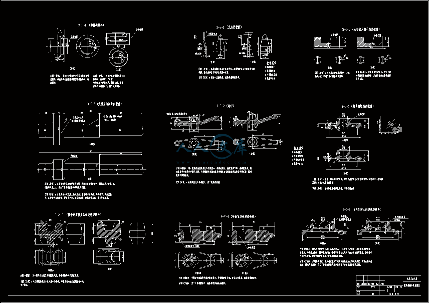
锻件的结构设计及工艺性分析设计【开题+答辩稿+外文翻译】【3张图纸】【优秀】

锻件的结构设计及工艺性分析设计【开题+答辩稿+外文翻译】【3张图纸】【优秀】

收藏

压缩包内文档预览:

资源预览需要最新版本的Flash Player支持。
您尚未安装或版本过低,建议您

锻件的结构设计与工艺性分析59页 19000字数+说明书+开题报告+论文+答辩稿+外文翻译+3张CAD图纸【详情如下】内封皮.doc外文翻译-金刚石刀具磨损的评价.doc封皮.doc答辩成绩评定.doc结构分析图(1).dwg结构分析图(2).dwg结构分析图(补充2).dwg锻件的结构设计与工艺性分析开题报告.doc锻件的结构设计与工艺性分析答辩稿.ppt锻件的结构设计与工艺性分析论文.doc目   录摘    要IAbstractII前    言1第1章 绪论31.1 目前锻件的应用31.2 目前国内外发展概况和发展趋势4第2章 锻件的结构设计及工艺性分析52.1 对锻造零件结构工艺性的要求52.2 锻件组织特点52.3 锻件的结构工艺性52.3.1自由锻件的结构工艺性52.3.2 模锻件的结构工艺性9第3章 锻件的结构设计错误示例及其改进123.1 模锻件的分模位置问题123.1.1 上下对称锻件的分模位置不应选在上平面或下平面123.1.2 倾斜锻件不宜采用折线分模133.1.3 左右对称的锻件,分模面不宜选在过度截面上143.1.4 高度小于或者等于台阶直径的圆饼类锻件,不宜轴向分模153.1.5 头部较大的轴类锻件不宜直线分模163.2 模锻件的模锻斜度问题173.2.1 模膛内侧不能与分模面垂直173.2.2 同一锻件的内模斜度不应比外模斜度小183.2.3 同一锻件上不宜出现多种模锻斜度203.2.4 分模面两侧的模锻斜度不能相互错开213.3 零件上过于复杂的部分不要锻出,应合理设计余块213.3.1 对于有凸缘的锻件223.3.2对于有难成形的复杂形状的锻件233.3.3 对于零件相邻台阶直径相差不大的锻件253.4 需增设定位块的锤上模锻件263.5 模锻件连皮的问题273.5.1 冲孔连皮不能太薄,也不宜太厚273.5.2 锻件内孔较大时,不宜用平底连皮283.5.3 锻件上的小孔不宜锻出连皮, 只进行压凹293.6 对于法兰较薄的锻件,在锻件两侧各增加一块工艺凸台敷料313.7 合理确定锻件的分合323.7.1 单拐曲线两件合锻323.7.2 轴套类零件两件合锻333.7.3 复杂模锻件的分锻343.7.4 有骤变横截面模锻件的分锻353.8 合理确定锻件的凸肩363.8.1 凸肩与锻件直径相差不大时不宜锻出凸肩363.8.2 高度过小的凸肩不要锻出373.9 自由锻件结构应力求简单383.9.1 自由锻件应尽量避免有锥形和斜度平面383.9.2 自由锻件应避免两曲面或曲面与棱柱面交接403.9.3 自由锻件应避免加强筋413.9.4 自由锻件不允许在基体上或在叉件内侧有凸台423.9.5 大型锻件台阶余面的重量不能忽视,锻造设备不能选择过大,也不能选择太小433.10 孔径小于30mm的孔,不宜锻出453.11 模锻件应尽可能直接模锻成形463.12 加大连接板的厚度473.13 复杂锻件应成对称形状,可使模具和夹具通用483.14 合理选择锻件上的倒圆半径493.15 不能忽视预锻成型503.16 平锻机上终锻成形时的冲孔芯料不能太薄513.17 合理安排毛刺、飞边的位置52第4章 结论54参 考 文 献55致    谢56摘    要目前国内外的锻造方法主要的仍然是自由锻和模锻,工业发达国家的模锻大大超过自由锻。因为模锻生产率高,锻件尺寸精度高,材料利用率高,纤维组织沿锻件轮廓分布,故力学性能好,故强度高,耐冲击抗疲劳。如果能结合胎膜锻、型砧锻,其经济效益会显著提高,“锻压”是人类发明的最古老的生产技术之一,也是机械制造业中重要的技术之一。它包含了锻造和冲压技术,以及与之相关的塑性变形技术。锻造作为金属加工的主要方法和手段,因此锻造工艺是发展趋势,锻造加工能保证金属纤维组织的连续性,使锻件的纤维组织与锻件外形保持一致,金属流线完整,可保证零件具有良好的力学性能与长的使用寿命,锻件是机器中负重载荷的零件,特别适合结构尺寸小而载荷大或受疲劳载荷的零件。不懂锻件设计就有可能违反锻造原理和锻造结构工艺性,轻则延长零件的生产周期锻造加工能保证金属纤维组织的连续性,使锻件的纤维组织与锻件的外形保持一致,金属流线完整,可保证零件具有良好的力学性能与长的使用寿命,增加制造困难,增加成本;重则可能无法把您设计的零件锻造出来。本设计将通过对各种锻件的具体案例的结构设计及其工艺性进行分析,把握锻件的结构设计及其工艺性的制造规律,并通过其规律的把握,达到灵活运用制造技术,合理设计零件结构及其工艺的目的。关键词:自由锻;模锻;锻造工艺;胎膜锻;结构AbstractCurrently,forging method at home and abroad,mainly remains Free forging and Roll forging,Model Forging of Industrial developed countries easily outnumbered Free forging. Beca mechanical property. High strength, impact fatigue resistance. "Forge" is one of the oldest use of high production rate of Roll forging,high dimension precision of forging,high utilization ratio of material and fibrous tissue distributes the outlines of forging,so it has good production technology of human invention, is one of the important technology in mechanical manufacturing industry. It includes the forging and stamping technology, and the plastic deformation associated with technology. Forging as main methods and means of metal processing . Forging ps histiocytomarocess can ensure the continuity of metallic fibrou , consistent with appearance of fibrous tissue and forgings forging, metal flow line complete, guaranteed parts with good mechanical properties and long service life, Forging is the weight-bearing loads in the machine parts, particularly suited to the structure of small size and loading large or subject to fatigue loading parts,If we can combine The fetal membrane hammers and the swage block hammers,the Economic efficiency will obviously enhances,so Forging craft is the trend of development, we will disobey Forging principle and Forging structure technology capability if we can not understand Forging design, the result range from not forging the components to protracting the production cycle, increasing manufacturing difficulties and costing this Graduation Project, we can grasp the law of the manufacture of structural design and forging structure technology capability by analysising the structural design of a wide range of forging and the technology capability, also nimbly use the technique of manufacture, reasonably design the structural and the craft by grasping the law.                Keywords:Free forging;Roll forging;Forging craft;The fetal membrane hammers;structural
编号:420521    类型:共享资源    大小:1.36MB    格式:RAR    上传时间:2015-03-29 上传人:上*** IP属地:江苏
35
积分
关 键 词:
锻件 结构设计 工艺分析 设计 开题 答辩 外文翻译 图纸 锻件的结构设计
资源描述:

锻件的结构设计与工艺性分析

59页 19000字数+说明书+开题报告+论文+答辩稿+外文翻译+3张CAD图纸【详情如下】

内封皮.doc

外文翻译--金刚石刀具磨损的评价.doc

封皮.doc

答辩成绩评定.doc

结构分析图(1).dwg

结构分析图(2).dwg

结构分析图(补充2).dwg

锻件的结构设计与工艺性分析开题报告.doc

锻件的结构设计与工艺性分析答辩稿.ppt

锻件的结构设计与工艺性分析论文.doc

目   录

摘    要I

AbstractII

前    言1

第1章 绪论3

1.1 目前锻件的应用3

1.2 目前国内外发展概况和发展趋势4

第2章 锻件的结构设计及工艺性分析5

2.1 对锻造零件结构工艺性的要求5

2.2 锻件组织特点5

2.3 锻件的结构工艺性5

2.3.1自由锻件的结构工艺性5

2.3.2 模锻件的结构工艺性9

第3章 锻件的结构设计错误示例及其改进12

3.1 模锻件的分模位置问题12

3.1.1 上下对称锻件的分模位置不应选在上平面或下平面12

3.1.2 倾斜锻件不宜采用折线分模13

3.1.3 左右对称的锻件,分模面不宜选在过度截面上14

3.1.4 高度小于或者等于台阶直径的圆饼类锻件,不宜轴向分模15

3.1.5 头部较大的轴类锻件不宜直线分模16

3.2 模锻件的模锻斜度问题17

3.2.1 模膛内侧不能与分模面垂直17

3.2.2 同一锻件的内模斜度不应比外模斜度小18

3.2.3 同一锻件上不宜出现多种模锻斜度20

3.2.4 分模面两侧的模锻斜度不能相互错开21

3.3 零件上过于复杂的部分不要锻出,应合理设计余块21

3.3.1 对于有凸缘的锻件22

3.3.2对于有难成形的复杂形状的锻件23

3.3.3 对于零件相邻台阶直径相差不大的锻件25

3.4 需增设定位块的锤上模锻件26

3.5 模锻件连皮的问题27

3.5.1 冲孔连皮不能太薄,也不宜太厚27

3.5.2 锻件内孔较大时,不宜用平底连皮28

3.5.3 锻件上的小孔不宜锻出连皮, 只进行压凹29

3.6 对于法兰较薄的锻件,在锻件两侧各增加一块工艺凸台敷料31

3.7 合理确定锻件的分合32

3.7.1 单拐曲线两件合锻32

3.7.2 轴套类零件两件合锻33

3.7.3 复杂模锻件的分锻34

3.7.4 有骤变横截面模锻件的分锻35

3.8 合理确定锻件的凸肩36

3.8.1 凸肩与锻件直径相差不大时不宜锻出凸肩36

3.8.2 高度过小的凸肩不要锻出37

3.9 自由锻件结构应力求简单38

3.9.1 自由锻件应尽量避免有锥形和斜度平面38

3.9.2 自由锻件应避免两曲面或曲面与棱柱面交接40

3.9.3 自由锻件应避免加强筋41

3.9.4 自由锻件不允许在基体上或在叉件内侧有凸台42

3.9.5 大型锻件台阶余面的重量不能忽视,锻造设备不能选择过大,也不能选择太小43

3.10 孔径小于30mm的孔,不宜锻出45

3.11 模锻件应尽可能直接模锻成形46

3.12 加大连接板的厚度47

3.13 复杂锻件应成对称形状,可使模具和夹具通用48

3.14 合理选择锻件上的倒圆半径49

3.15 不能忽视预锻成型50

3.16 平锻机上终锻成形时的冲孔芯料不能太薄51

3.17 合理安排毛刺、飞边的位置52

第4章 结论54

参 考 文 献55

致    谢56

摘    要

目前国内外的锻造方法主要的仍然是自由锻和模锻,工业发达国家的模锻大大超过自由锻。因为模锻生产率高,锻件尺寸精度高,材料利用率高,纤维组织沿锻件轮廓分布,故力学性能好,故强度高,耐冲击抗疲劳。如果能结合胎膜锻、型砧锻,其经济效益会显著提高,“锻压”是人类发明的最古老的生产技术之一,也是机械制造业中重要的技术之一。它包含了锻造和冲压技术,以及与之相关的塑性变形技术。锻造作为金属加工的主要方法和手段,因此锻造工艺是发展趋势,锻造加工能保证金属纤维组织的连续性,使锻件的纤维组织与锻件外形保持一致,金属流线完整,可保证零件具有良好的力学性能与长的使用寿命,锻件是机器中负重载荷的零件,特别适合结构尺寸小而载荷大或受疲劳载荷的零件。不懂锻件设计就有可能违反锻造原理和锻造结构工艺性,轻则延长零件的生产周期锻造加工能保证金属纤维组织的连续性,使锻件的纤维组织与锻件的外形保持一致,金属流线完整,可保证零件具有良好的力学性能与长的使用寿命,增加制造困难,增加成本;重则可能无法把您设计的零件锻造出来。本设计将通过对各种锻件的具体案例的结构设计及其工艺性进行分析,把握锻件的结构设计及其工艺性的制造规律,并通过其规律的把握,达到灵活运用制造技术,合理设计零件结构及其工艺的目的。

关键词:自由锻;模锻;锻造工艺;胎膜锻;结构

Abstract

Currently,forging method at home and abroad,mainly remains Free forging and Roll forging,Model Forging of Industrial developed countries easily outnumbered Free forging. Beca mechanical property. High strength, impact fatigue resistance. "Forge" is one of the oldest use of high production rate of Roll forging,high dimension precision of forging,high utilization ratio of material and fibrous tissue distributes the outlines of forging,so it has good production technology of human invention, is one of the important technology in mechanical manufacturing industry. It includes the forging and stamping technology, and the plastic deformation associated with technology. Forging as main methods and means of metal processing . Forging ps histiocytomarocess can ensure the continuity of metallic fibrou , consistent with appearance of fibrous tissue and forgings forging, metal flow line complete, guaranteed parts with good mechanical properties and long service life, Forging is the weight-bearing loads in the machine parts, particularly suited to the structure of small size and loading large or subject to fatigue loading parts,If we can combine The fetal membrane hammers and the swage block hammers,the Economic efficiency will obviously enhances,so Forging craft is the trend of development, we will disobey Forging principle and Forging structure technology capability if we can not understand Forging design, the result range from not forging the components to protracting the production cycle, increasing manufacturing difficulties and costing this Graduation Project, we can grasp the law of the manufacture of structural design and forging structure technology capability by analysising the structural design of a wide range of forging and the technology capability, also nimbly use the technique of manufacture, reasonably design the structural and the craft by grasping the law.                Keywords:Free forging;Roll forging;Forging craft;The fetal membrane hammers;structural

内容简介:
密级:内部锻件的结构设计与工艺性分析Forgings Structural Design And Technological Analysis院 系:机械系专 业/班 级:机械设计制造及其自动化0702班学 号:220072607学 生 姓 名:方隽潇指 导 教 师:尚洪光 (工程师)2011 年 6 月毕业设计(论文)指导教师审阅意见题目: 锻件的结构设计与工艺性分析评语:指导教师: (签字) 时 间:毕业设计(论文)评阅教师审阅意见评语:评阅教师: (签字)时 间: 题目:锻件的结构设计与工艺性分析Evaluation of diamond tool wearW.PoliniS.TurchettaReceived:28 May 2003/Accepted:9 January 2004/Published online:19 May 2004?Springer-Verlag London Limited 2004W.PoliniS.Turchetta(u)Dipartimento di Ingegneria Industriale,Universitdi Cassino,via G.di Biasio 43,03043 Cassino,Italy E-mail:turchettaunicas.itTel.:+39-0776-2994013Fax+39-0776-2993886AbstractThe present study proposes a test protocol regarding the wear of sintered diamond tools.A set of parameters which characterise the grade of wear,and its relationship with the cutting ability of the examined tools,are established.The proposed protocol establishes the procedure and the equipment for carrying out the tests,the features of the materials to use and the format of the report to present the results obtained.The developed test protocol indicates an universally applicable way for measurement of the wear of the diamond tool.It is an indispensable instrument for correctly carrying out the wear tests and for reliably interpreting the results.The protocol developed so far mainly regards laboratory tests,considering the slowness and precision of the measurements involved.Given the total absence of norms,this protocol could be absorbed by national and international norm establishing organisations.This protocol has also been applied to two types of tools and the results obtained have appeared reliable and replicable.The test protocol proposed in this study makes it possible to overcome the difficulties connected to the scarcity of technical data regarding the properties of the tool,which is typical in this field since the recipes for tool manufacturing are patented.Keywords Cutting toolDiamond sintered millMacro-geometric wear parametersTest protocolWear1 IntroductionThe increasing demand both in the industrial field and in urban furnishing for elements in natural stone with increasingly complex geometry makes it necessary to use increasingly flexibleand automatic machines,such as numerically controlled machining centres.These centres make it possible to carry out large numbers of operations by means of diamond mills.No studies on optimisation of the cutting process have been carried out for these jobs.Therefore,until now,a sometimes imperfect solution has been accepted1,2.Optimisation means reducing machining costs and/or times and/or improving the quality of the products obtained by working on different factors,such as cutting strengths,tool properties,process temperatures and vibrations35.A critical point is the actual tool.Optimisation of the tool properties in relation to the wear process leads to optimisation of the whole process.The present study aims at understanding the diamond tool wear process.This behaviour has a direct influence on energy consumption and on tool life. In particular,diamond tool wear necessitates appropriate definitions and measurements.In other words,it is necessary to establish,in a clear and unequivocal way,the parameters that characterise the wear process and their measurement by means of a reliable and replicable procedure.The aim of the present study is to define a test protocol regarding wear of sintered diamond tools.The total absence of bibliographic references or norms regarding the procedures for conducting wear tests on sintered diamond tools has made it imperative to prepare an adaptable test protocol that offers a universally valid mode for carrying out the macro-geometric wear test with the aim of obtaining replicable and comparable results.It is an indispensable instrument for correctly carrying out tests and for reliably interpreting the results.It offers stone machining companies the possibility of comparing tools that producers sell as being similar,but during machining present extremely differing performances.In fact,at the present state,diamond tools available on the market are characterised solely by the specification of the material they can process,while other technical features are subject to industrial patent and,therefore,are unknown to marble and granite machining firms.This protocol could be used by tool manufacturers to evaluate the performance of their tools compared to those of competitors and at the same time to equip their sup- plies with information on the useful life of the tools offered.This last aspect represents a service that transformers are requesting with increasing insistence.The guide lines forming this protocol have been taken from existing norms for single-cut tools6.The protocol developed so far regards tests to be carried out in the lab,given the precision and thus the slowness of the tests involved.The protocol has allowed the development of knowledge of the wear process of diamonds,which constitute tools for machining natural stones,which in turn constitutes the basis for machining optimisation.The following paragraphs describe the properties of diamond tools used in cutting natural stones and their relationship with wear.The test protocol and its application to two types of tools are described in the following sections.2 Wear of sintered diamond tools for machiningnatural stoneDiamond tools used for natural stone machining can be classified in cutting tools,such as wires,blades,disks and mills, and tools for machining surfaces,such as grinders and mills of different shapes and profiles.In both cases the tool consists of a support,a super-abrasive grit and a bound.The support is the part of the tool upon which the abrasive grit is fixed.It gives the tool the appropriate form,transmits kinetic energy from the machine rollers to the abrasive grit and absorbs the strengths created during the machining process.The super-abrasive grit has the task of removing the material.Its properties are granulometry,shape and bound matrix concentration.The granulometry expresses the measurement of the super-abrasive grit size.Theform of the grit may be regular or irregular according to the quality of the actual grain.Concentration is the quantity,in weight,of the diamond grit for sector unit volume.The bound is that alloy which blocks the super-abrasive to the tool support so that it can carry out the cutting,milling,sharpening,smoothing and profiling economically and in a technically correct manner.The bound must guarantee two contrasting requisites:cutting capacity and long tool life.Finally,the bound must have wear resistance suited to the type of tool super-abrasive,such as allowing the correct protrusion in relation to the process to be carried out and the features of the material being machined,but above all it must allow the loss of worn grit to encourage replacement by new grit existing within the matrix.The metals making up the bound mixture are iron,copper,tungsten,cobalt and nickel.The diamond tool wear is the result of the wear progression of both diamond grit and tool binding.It is characterised by a sequence of steps7,8. Firstly,there is a progressive increase of grit protrusion with respect to binding surface,due to binding erosion,that makes the grit come into contact with the workpiece.An emergent crystal appears on the tool surface:its cutting ability is scarce because of its small height of protrusion.A binding that is too hard would make the abrasive grit exposition so difficult the tool sector results polished before the diamond grits are completely emerged by binding.The progressive erosion of the binding makes the whole crystal appear on the surface of the tool sector.A whole crystal is a diamond grit that has a large height of protrusion and a minimum surface damage.It has the best cutting performances.Once the workpiece is contacted,the grit is rounded off so much that a plateau is generated on the grit top.It generates mechanical friction and thermal effects that polish the diamond grits.An high percentage of polished grits makes the surface of the tool sector so vitreous,to cause a less efficient cutting ability.The intermittent contact with the workpiece,caused by the tool rotation,leads to a cyclic load on the diamond grit,which dete- riorates the grit ability to contrast the cutting forces and,finally, the grit breakage.This phenomenon is enlarged by the heterogeneous nature of the workpiece and by the machining vibrations. The diamond grits result is characterised by microfractures and microcracks that increase the number of cut edges on the grit surface,even if they reduce the penetration depth.Wear progression leads to a completely fragmentary particle or to a worn matrix in such a way that the diamond grit is released.The pull-out is the phenomenon due to the release of a diamond grit from binding, and to the consequent formation of a cleavage.It may accelerate tool wear,when a diamond grit is removed from the metallic binding before its useful life is completed.In this case the resulting cleavage will be very big and it will involve a considerable binding wear before a new abrasive grit emerges.Conversely, if the grit is removed from the metallic binding after its useful life is consumed,the cleavage will be less deep and less volume of binding will be consumed in order to remove a new grit.The pull-out is due to an increase either of the cutting efforts or of the cohesion power to keep fixed diamonds.New grits will emerge on the tool cutting surface and the wear cycle will begin again.The progression of diamond tool wear consumes the diamond and the binding constituting the tool.This implies the decrease of both the weight and the diameter of the whole tool and the change of the cylindrical shape of the diamond tool.The tool moves away from its original cylindrical boundary surface.We have evaluated the consumption of a diamond mill by means of four variables that depend on the whole tool:the decrease of the tool weight,the decrease of the tool diameter,the variation in the cylindricity of the tool shape and the grinding ratio.Cylindricity is a condition of a surface of revolution where all the points of the surface are equidistant from a common axis. These three macro-geometrical variables are directly connected with wear progression and,at the same time,they are simple to measure.They have been used to monitor the mill wear during stone machining.They have been called macro-geometric wear variables.3 Test protocol for the macro-geometric wear of sintered diamond toolsThe protocol regarding macro-geometric wear specifies the material to be machined,standard conditions of the workpiece,tool properties,the cooling fluid to be used and the cut conditions to be applied during the test.The machine that carries out the test must be of rigid structure and not tend to vibrate or bend anomalously during the test.The machine-tool for the test must have a command for continuous speed variation covering the whole range of speeds used during the actual machining.The method to be followed to achieve the test regarding tool life is the same as that used for achieving the cut operation with observations to be noted and measurements to be made.The macro-geometric wear test consists of carrying out various cutting operations in succession and interposing the measurement of the macro-geometric wear parameters between one cut and the next.The test report will contain the graph regarding the trend of the macro-geometric wear parameters in relation to the volume of removed material.Below we have the full text of the protocol.3.1 Material to machineGiven the large number of materials used in the natural stone machining field it is not advisable to compare tests carried out on differing materials or on materials having similar properties.For this reason the properties of the materials used must be specified in a test summary according to the details given in Table 2 for the two considered granites:black Africa and Sardinian granites. 3.2 Standard conditions of the workpiece The cutting test must involve the whole surface of the tool(i.e.,the radial depth of cut must be equal to the diameter of the tool). It must be carried out on slabs having dimensions that will minimise vibrations of the work-piece during the test.The spindle and the table where the workpiece will be fixed must be stable and well-balanced.During positioning of the workpiece on the table bending of the work-piece must be carefully avoided.3.3 ToolTool wear strongly depends on the materials constituting the actual tool.In the test resume,characteristics of the tool used during the test must be specified according to indications given in the Table 3 for the two considered tools.3.4 Cutting fluidAll cutting tests in which the cutting fluid is not a variable must be achieved using water as the cutting fluid.The cutting fluid jet must be directed onto the face of the tool and completely hit the active part of the tool.If possible,indicate jet capacity and pressure in the test resume.3.5 Cut conditionsFor all cutting tests in which feed rate f,axial depth of cut a,and cutting speed vt do not constitute the main test variables,cutting conditions must have the reference values shown in Table 4. If the aim of the study is to evaluate the relationship among tool wear and cutting parameters,cutting conditions must be planned on many different levels,inside the range of interest from an industrial point of view,through design of experiment techniques (DOE)techniques.3.6 Macro-geometric wear test procedure3.6.1 IntroductionThe aim of the tool life test is to establish by means of experimental tests how one or more parameters influence the life of the cutting tools.The reason for deciding that the life of a particular cutting material is over is often different for different machining operations.The simplest case that can occur is when the tool becomes completely unusable.In the majority of cases the tool wears progressively and the machining carried out becomes less satisfactory,for instance,cut strengths increase and produce in tolerable bending and vibrations.Determining the end of tool life is thus fixed for reasons of comparability. The diamond tool wear is the result of progressive consumption of both diamond and binding.The diamond grit wear is strongly connected with the grit properties,while the binding consumption is a function of binding hardness.The microgeometric effect is both the progressive rounding and breakage of the diamond grits,constituting the sectors layer by layer, and the erosion of binding.The macro-geometric result is the decrease of both the diameter and the weight of the tool together with the possible change of the tool cylindrical shape in time.The wear progression of a diamond tool strongly influences the tool performances and,therefore,the effectiveness and the efficiency of the stone machining.In fact,a worn tool increases the loss of the cutting ability,the amount of vibrations produced during the cutting process,the probability to have a discontinuous process and,therefore,the presence of chippings and undulations on the resulting stone product.The tool performance is a critical element for the optimisation of the stone machining.3.6.2 Machine-toolThe machine used for the test must be of rigid structure and not tend to vibrate or bend anomalously during the test.The machine-tool must have a command for continuous speed variation covering the whole range of speeds used.Furthermore, a variable speed command allows the exact predetermination of cutting speeds and reduces the time necessary for obtaining the tool life curve.3.6.3 InstrumentationThe following instruments are necessary for carrying out the necessary measurements and must be accurately constructed in order to be able to verify the tolerances indicated in the present instructions: A stopwatch to register cutting times An optical microscope equipped with a micrometric device for measuring the tool size ?An electronic balance with a sensitivity of 0.01 g An instrument for measuring cutting liquid flow(may be obtained by measuring the time necessary to empty a container having a known volume)3.7 Procedure for tool macro-geometric wear testThe conditions vary in each single case and,therefore,the test procedure regarding tool life can only be described in general terms.The method to be followed to achieve the tool life test is the same one used to achieve good cut operations with,in addition,the necessary precautions to be taken,observations to be noted and measurements to be made. Before beginning the test,make sure that the machine-tool,the work-piece and the tool correspond to the instructions of thepresent protocol. 3.8 Resume of the test and expression of the results In the test resume the following results must be given:Changes in tool diameter with increasing volume of the removed stoneChanges in tool weight with increasing volume of the removed stoneChanges in tool cylindricity with increasing volume of the removed stone4 Application exampleThe protocol developed has been applied to study the wear of two types of tools put on the market by a well-known producer for the machining of two types of granites(see Table 1).The cut tests have been carried out on African black granite and Sardinian granite,whose properties that must be reported according to the test protocol are given in Table 2.Linear cuts have been carried out on slabs whose dimensions are 1000 mm500 mm in order to allow a proper fixture on machine tool table,and with a thickness of about 30 mm for the M9Z3 mill and of about 40 mm for the M9BN.Cuts have been put at a distance assuring a complete independence among the following cuts.The parameters characterising the two types of tools are given in Table 3.Water,the cooling fluid commonly used in the machining of natural stones, has been used,directed onto the cutting zone in question by means of an appropriately positioned nozzle system and a duct inside the actual mill.The test conditions are given in Table 5. A NC 3-axis machining centre was used.It has been equipped with a continuous control chuck rotation speed and feed rate.At the end of each cut,the tool has been put off the spindle,it has been cleaned in order to remove the machining tailings,then,its diameter,weight and its cylindricity have been evaluated.The weight of the mill has been measured by an electronic balance with a sensitivity of 0.01 g.The diameter has been measured by a Leica optical microscope in six positions uniformly distributed along the tool boundary surface.The mill diameter has been considered the average value of the six realised measurements. The microscope has a resolution of 0.5m and a measuring uncertainty of about 2.6m.The diameter measurements have been used to evaluate the cylindricity,too.A couple of coaxial cylinders within which the values of the measured diameters lie has been identified.The radial distance between the two coaxial cylinders is equal to the cylindricity control tolerance value.Table 1.Example of test protocol.Test protocolMaterial to machineBlack Africa granite Properties shown in Table 2Sardinian granite Properties shown in Table 2Standard conditions of the work-piece slabs Dimensions 1000 mm500 mm30 mmDimensions 1000 mm500 mm40mmToolsM9Z3 Properties shown in Table 3M9BN Properties shown in Table 3Cutting fluidwater pressure 0.2 MPa flow 10 l/minCut conditionsFeed rate f See Table 4Cutting depth vt See Table 4Cutting speed a See Table 4Macro-geometric wear test procedureMachine-toolNC 3-axes machining centreInstrumentationLeica optical microscope Sensitivity 0.5mElectronic balance Sensitivity 0.01 gStop-watch Sensitivity 0.1 sProcedure for tool-wear test6 measurements of diameter uniformly distributed along the tool lengthweigh tool three times after each machining stepResults resumeTool diameter change vs.volume of removed stoneTool weight change vs.volume of removed stoneTool cylindricity change vs.volume of removed stoneTable 2.Properties of the material to machineMaterial properties Sardinian granite African black graniteDensitykg/m3 2608 3010Water absorption% 0.25 0.05Compressive strengthMPa 145 180Abrasion resistanceHa 40 65Impact resistancecm 90 90Knoop hardnessMPa 5000 30004.1 Results and discussionThe study has allowed the determination of the change of the previously defined macro-geometrical variables as a function of the removed stone volume.This means to monitor the macro geometric wear variables in time.Figure 1 shows the trend of the mill diameter for two kinds of tools.The curves connected with the M9Z3 mill extend as far as about 90 000 cm3 of removed material and they have a linear trend.The curves to the M9BN mill arrive up to 50 000 cm3 of the removed material and they have a curvilinear trend.The overall decrease of the mill diameter is the same for the two considered tools:it is about 6 mm.This means that the M9BN mill machines one half the amount of stone that M9Z3 removes be- fore it breaks out.A linear trend involves a constant wear rate in time and,therefore,a progressive wear of the mill that may be easily foreseen.Figure 2 presents the reduction in weight for the two kinds of mill.A comparison between the curves is carried out to the same considerations previously emerged by the analysis of the diameter decrease.The weight decrease of the M9Z3 mill is linear,thus implying a linear wear rate and,therefore,a uniformly decreasing cutting ability.Figure 3 reports the tool cylindricity for the two kinds of mills as a function of the removed stone volume.The curves connected with the M9Z3 mill show a random and damped oscillation around the initial value of about 0.02 mm.The curves related to the M9BN mill increases strongly from 0.01 mm to 0.1 mm.This means that the cylindrical profile of the M9Z3 mill is unchanged with wear progression,whereas the M9BN mill changes its cylindrical shape very quickly due to diamond and binding consumption.The profile of the generatrix of the M9BN cylindrical boundary surface appears rounded for about 0.10 mm at the end of the wear progression(75%of the weight decrease).The trace,impressed by the mill on the stone during the machining,changes so much with the wear progression that the surface bounding the cutting groove assumes a convex profile that has difficulty coupling with the other components of a paving decoration.Therefore,a high value of cylindricity involves the need of further finishing operations to reduce or to eliminate the rounded profile impressed by the worn cutting mill.Finally,all three of the considered macro-geometric variables show that the M9Z3 mill has cutting performances higher than those of the M9BN mill.It may machine a high amount of stone before breaking out.The decrease of its weight and its diameter is linear with the volume of removed granite.Therefore,it is easy to calculate the change of the mill diameter with the wear progression that is commonly used to correct the path of the mill axis for NC machining.Moreover, the cylindrical shape of the mill is unchanged with the wear progression.On the whole we can say that the protocol developed allows us to achieve results in line with the properties of the tool and allows us to compare tools having different characteristics.Fig.1.Changes in tool diameter with increasing volume of removed stoneFig.2.Changes in tool weight with increasing volume of removed stoneTable 3.Tool propertiesTool properties M9Z3 M9BNChemical composition of binder Co-Cu-Al-Fe-Si Co-Cu-Al-Fe-SiCu/Co=0.285 Cu/Co=0.51Diamond mesh# 45/50 45/50Diamond concentrationKts/cm3 0.9 1.0Tool weightg 238 177Tool diametermm 23 20Sectors number 5 6Depth of sectormm 35 44Table 4.“Standard”conditions of cuttingStone Axial depth of cut Cutting speed Feed ratemm rpm mm/minGranite 20 mm 5000 300Marble 20 mm 5000 400Granite 30 mm 4500 200Marble 30 mm 5000 400Granite 40 mm 4500 200Marble 40 mm 4500 400Table 5.Experimental planTest Mill type Process variablesCutting speed Feed rate Axial depth of cutrpm mm/min mmI M9Z3 4500 200 30II M9BN 4500 200 405 ConclusionsThe present study proposes a test protocol for the measuremen of macro-geometric wear of diamond tools.In this way it is possible to obtain comparable and replicable results to characterize the wear of sintered diamond tools.The protocol specifies the material to be machined,standard conditions of the work-piece, tool properties,the cooling fluid to use and cut conditions to be applied during the test.The test report will contain the graph regarding the trend of the macro-geometric wear parameters in relation to the volume of material machined.The protocol developed has been applied to study the wear of two types of tools put on the market by a well-known producer for the machining of two types of granites.Acknowledgement This work was carried out with funds received from the Italian M.I.U.R.(Ministry of Instruction,University and Research)within the project entitled“Stone manufacturing technologies”(COFIN01).The authors wish to thank CO.MARMI s.n.c in Cassino for supplying the stone for experimental tests. References1.Tonshoff HK,Warnecke G(1982)Research on stone sawing.In:P.Daniel(ed)Advances in ultrahard materials application technology.DeBeers Industrial Diamond Division,pp 36492.Asche J,Tonshoff HK,Friemuh T(1999)Cutting principles,wear and applications of diamond tools in the stone and civil engineering industry.Proceedings Int Workshop on Diamond Tool Production,pp 1511573.Luo SY,Liao YS(1995)Study of the behaviour of diamond saw-blades in stone processing.J Mater Process Technol 51:2963084.Luo SY,Liao YS(1992)Wear characteristics of sintered diamond composite during circular sawing.Wear 157:3253375.Wrigt DN,Wapler H(1986)Investigations and prediction of diamond wear when sawing.Ann CIRP 35:2392446.International Standard Organization(1977)ISO 3685,Tool-life testing with single point turning tool7.Jahanmir S,Ramulu M,Koshy P(1999)Machining of ceramics and composites.Dekker,New York8.Carrino L,Polini W,Turchetta S(2002)Wear progression of diamond mills:a micro-geometric study.Proceedings Euro PM2002 European Conference on Hard Materials and Diamond Tooling,Lausanne,Switzerland,79 October 2002,pp 156161金刚石刀具磨损的评价W .Polini S .Turchetta收到:5月28日2003/接受:1月9日2004/出版:2004年5月19,斯普林格伦敦有限公司2004年摘要目前的研究提出了一个关于烧结而成的金刚石刀具磨损的测试议定书。用来描述刀具磨损等级的参数设置及其被测刀具切屑能力的表达式被建立起来。已拟的议定书制定了即将要进行测试的过程、需要的仪器 、所用材料的性质特征以及提交测得实验结果的报告的格式。此先进的测试议定书表明了一种普遍可用的测量金刚石刀具磨损的方法。这也是正确地进行磨损试验与可靠地解释试验结果的依据。议定书发展到迄今主要是应用于实验室试验, 分析所得测量值的迟缓性和精确性。假使缺少全部标准,这个议定书能够吸引国内和国外的标准制定机构的关注。此议定书也已经应用于两种类型的刀具,所测定的结果显示很可靠并且可以应用。研究中拟定的测试议定书使克服有关刀具性能技术数据不足的难题成为可能,由于刀具的生产具有专利性质,所以,该议定书在这个领域是个很典型的提议。关键词 :切屑刀具;烧结金刚石磨削;宏几何学磨损参数;测试议定书;磨损1 引言在工业领域中和城市建设中,由于不断增加对拥有复杂几何形状的天然石材元件提供的强烈需求,这就必须要使用日益增加的自动柔性机床,例如数字控制组合加工中心。这些加工中心能够通过金刚石磨削来实现大量的操作指令。现在还没有对这样的作业实行切屑过程优化的研究,所以,一种时而不完美的解决方法已经被接受。优化就意味着降低加工成本切屑时间改进不同的影响因素所得到的产品质量,例如切屑力、刀具的性质、过程温度和振动。决定性的一点就是现行的刀具。与磨损过程相关的刀具性质的优化会带来整个过程的优化。现在的研究目的是理解金刚石刀具的磨损过程。这种研究对能量损耗和刀具寿命有很大的影响。特殊地,金刚石刀具磨损需要适当的界定和测量。总而言之,以清晰明确的方式建立相关参数是非常必要的,这些参数可以通过可靠并且可利用的程序来描述磨损过程和测量方法。目前研究的目的是确定一个关于金刚石烧结刀具磨损的测试议定书。由于缺少用来指导有关金刚石烧结刀具磨损试验方法的书目参考和标准,而且还要进行可获得应用性和比较性较好的试验结果的宏几何学磨损试验,这使得制定一个可提供普遍正确样式的适应性好的测试议定书变得紧迫。此议定书是正确地进行试验和可靠地解释试验结果必不可少的工具。它为石料切削公司比较生产商所卖相似刀具的性能提供了可行性。但是,在切削过程中,存在的性能还是有所不同。实际上,从目前的状况看,现在市场上的金刚石刀具完全通过它们所拥有的材料的性能来描述,而其他的技术特性都受限于产业专利,所以,云石和花岗岩加工公司却全然不知。这个议定书能够让刀具生产商通过和其他竞争者比较来评价他们的刀具性能,与此同时,还可以利用卖方刀具的有效期信息来配备他们的供应。这最后的方面代表一种服务,即变换器要求增加持续的强迫动作。对于单刃刀具来说,组成这个议定书的指标已经从现存的标准中去除。发展到迄今的议定书认为试验是在实验室中进行的,指定试验涉及的精度和迟缓性。此议定书容许金刚石过程磨损知识的发展,这种金刚石是构成加工天然石材的刀具,也是构成加工优化方法的基本。下面的段落用来描述加工天然石材的金刚石刀具的性能,以及它们自身与磨损的关系。测试议定书及其在两种刀具上的应用将在接下来的段落里描述。2 加工天然石材的金刚石烧结刀具的磨损 应用于天然石材加工的金刚石刀具可以根据刀削工具来分类:如线状刀具、片状刀具、盘状刀具和磨削刀具,还有加工平面的机床,例如具有不同类型和轮廓的磨床和铣床。两个例子中的刀具都由支承、超级-金刚研磨料颗粒和结合体组成。支承是研磨料颗粒固定在刀具的那部分,它赋予刀具适当的形式,它把机械能从机床辊子传递到研磨料颗粒,同时吸收加工过程中产生的力。超级-金刚研磨料颗粒担负着去除材料的任务,它的性能是粒度测量、造型和限制基体密集度。粒度测量表示对超级-金刚研磨料颗粒尺寸的测量,根据实际存在的晶粒性质判断,研磨料颗粒的形式可能是规则的,也可能是不规则的。密集度是扇形单位容量的重量值。结合体是用研磨料颗粒来阻塞刀具支承的硅铝合金,利用工业上正确的技术方法,它能够更加经济地用来实现切屑加工、铣削加工、磨削加工、精加工以及仿形加工等。此结合体必须保证两个相反的要素:提高切屑能力和延长刀具寿命。最后,结合体必须具有适用于超级-金刚研磨类型刀具磨损的抵抗力,例如允许试验过程中出现与之相关的隆起以及被加工材料的性征,但最重要的是此结合体必须要允许存在于母体内部新的晶粒积极的弥补已磨损晶体的损失。配制此结合体混合物的金属有铁、铜、钨、钴、以及镍。金刚石刀具磨损是金刚石晶粒和刀具材料结合物磨损发展的结果。它可以用下面的步骤顺序来描述首先,由于结合面的腐蚀,结合体表面的晶体隆起不断增加使晶粒和工件相接触。一种突起的结晶物出现在刀具表面。这种微小高度的隆起导致刀具切屑能力的下降。这种坚硬的结合体将会使超级-金刚研磨料颗粒曝光变得很困难,以至于在金刚石晶粒完全出现在结合体上之前,刀具区段就产生了研磨。结合体的逐渐腐蚀使全部的结晶物出现在刀具区段的表面上所有的结晶体是具有较大高度隆起和微小表面破坏的金刚石颗粒。它具有很好的切屑性能。一旦工件被接触,晶粒便大量地环绕形成,以至于在晶粒顶部好似形成一个小高原,它可以产生磨光晶粒的机械摩擦和热作用。部分晶粒的高百分率使刀具区段的表面变得透明,这会导致效率较低的切屑能力。刀具旋转所带来与工件的间歇性接触,导致金刚石晶粒产生周期性载荷。由于工件的不同特性和机械振动,这种现象会被扩大。金刚石晶粒的产物可以通过增加晶体表面的切屑边缘数量的微裂缝和微裂纹来描述,尽管他们会减小渗透深度。磨损的逐渐加剧会导致完全破碎的微粒或者母体的破损,这种磨损会使金刚石晶粒被释放。由于结合体金刚石晶粒的释放以及产生的组织分裂,使得这种脱落成为一种现象。当金刚石晶粒在其有效期结束前从金属粘合物上脱落,这会加速刀具的磨损。在这个例子中,最终的分裂将会很大,它将包括在金刚研磨料颗粒出现前所考虑到的结合体磨损。相反地,如果晶粒在它的使用寿命结束后从金属结合体上脱落,分裂将不会很深,移动新的晶粒也不需要消耗太多的结合体体积。脱落现象归结为切屑力或保持固定金刚石结构的凝聚力的增加。新的晶粒将会出现在刀具加工表面,此时,磨损周期将再一次开始。金刚石刀具磨损的进程消耗组成刀具的金刚石和结合物质。这就意味着整个刀具的重量和直径尺寸的减少以及金刚石刀具圆柱形状的改变。刀具从它原始的圆柱边界线处开始移动我们通过决定于整个刀具的四个变量对金刚石磨头的耗损进行评价:刀具重量的减少;刀具直径的减小;刀具外形圆柱度和磨削率的变化。圆柱度是旋转表面上所有的点与公共轴线等距离的状态。这三个宏几何学变量都与磨损进程直接相关,同时,它们的测量都很容易。可以用来监视石料加工过程中的磨头磨损。它们被叫做宏几何学磨损变量。3烧结金刚石刀具的宏几何学磨损测试议定书关于宏几何学磨损的议定书明确了测试过程中的待加工材料,工件的标准条件,工件的性质;使用的冷却液和应用的切削条件。在进行试验的过程中,机床必须具有刚性的结构,不能有振动的倾向和不规则的变形。试验用的机床要有控制速度持续变化的指令,来补偿现行加工过程中应用的整个速度范围。实现有关刀具寿命试验所采用的方法与完成有关注释观测结果和测量的方法相同。宏几何学磨损试验由顺次进行的各种切削过程和插入介于两切口之间的宏几何学磨损参数测量值组成。试验报告要由关于去除材料体积的红几何学磨损参数相关趋势的图表,下面是我们议定书的全部正文。3.1 机床材料使用在天然石材加工领域的材料有很大的数目,利用不同性质的材料或者性质相似的材料进行对比性试验是不可取的。由于此原因,所用机床材料的性能必须规定在试验一览表中根据表2所列出了两种论述的花岗岩的具体细节,这两种花岗石是:黑色非洲花岗岩和撒丁岛花岗岩。3.2 工件的标准条件切屑试验必须包含整个刀具的表面(例如,切屑径向深度必须要等于刀具的直径)。在试验过程中,必须要在能够减小工件的振动且具有一定面积的板坯上进行试验。固定工件的转轴和平台必须要保持良好稳定性和平衡性。必须要避免工件定位在工作台时产生的变形。3.3 刀具刀具的剧烈磨损决定于现行刀具的组成材料。在继续的试验过程中,所使用的刀具的特性必须根据表3中论述的两种刀具的指示信息进行规定。3.4 切削液所有切削液不变的切屑试验都必须利用水作为切削液,这样才能完成。切削液必需直接喷溅在刀具表面上并且完全作用在刀具的工作部分,如果可能的话,最好显示后续试验过程的喷溅能力和喷流压力。 3.5 切削条件所有切削试验中的进给速度f、轴向切削深度a和切削速度vt不能组成主要的试验变量切削条件必须要用到表4中所示的参考值。如果研究的目的是评价刀具磨损和切削参数之间的关系,那么切削条件必须通过实验技术方法(DOE)的设计制定许多不同的等级,使其包含在来自产业观点兴趣的范围内。3.6 宏几何学磨损试验法3 .6 .1 引言刀具耐用度试验的目的是通过实验性检验确定一个或几个参数如何产生对切削刀具寿命的影响。由于加工方法的不同,决定特殊材料切削刀具寿命结束的原因也常常是不同的。最简单的例子就是发生在刀具完全报废的时候。在大量的实例中,刀具的逐渐磨损和所实行的切削操作都令人感到很不满意,例如,切削力的增加和加工过程中的变形和振动。固定比较性的因素决定刀具寿命的终止。金刚石刀具磨损是金刚石和结合体逐渐消耗的结果。金刚石晶粒的磨损与晶粒的性质的关系紧密相关,粘结体的消耗是粘结硬化的函数,宏几何作用就是组成区段层的金刚石晶粒消失和损坏以及结合体的腐蚀。宏几何作用的结果会导致刀具直径和重量随着刀具柱状形状的适时变化而减小。金刚石刀具磨损的发展强烈地影响刀具的性能,而且还会影响到石材加工的效果和效率。实际上,一个磨损的刀具会加快切屑能力的损失,增加制造切屑过程中的振动的数目以及产生断续切屑过程的可能性。所以,最终的石材制品上就会出现片状或波浪形误差。因此,刀具的性能是石材加工的关键因素。3 .6 .2 机床在测试过程中,应用于试验的机床一定要具备刚性结构,而且不能具有不规则振动和弯曲变形的趋势。试验用的机床要有控制速度持续变化的指令,来补偿现行加工过程中应用的整个速度范围。此外,变化的速度指令容许切屑速度的精确设定,还可以减少获得刀具寿命曲线所需要的时间。3 .6 .3 仪器设备为了能够验证显示在当时指示仪器上的误差,必须要准备好实行必要测量并且制造准确的下列仪器:l 记录切屑时间的秒表l 测量刀具尺寸的具有测微装置的光学显微镜l 灵敏度为0.01g的电子秤l 测量切屑液流速的仪器(可以通过测量已知容积容器的排空时间来获得)3.7 宏几何磨损试验的过程由于每个具体例子的情况是变化的,所以,刀具寿命的试验过程只能泛泛地描述。完成刀具寿命试验采用的方法与完成良好加工过程所用的方法相同,此加工过程包括采用必要的预防措施,记录观测值以及进行必要的测量。在开始试验之前,必须保证机床、工件和刀具与当时议定书中的指示相一致。3.8 试验的概况总结与试验结果的表达由此试验,可以得出以下结论:l 刀具直径随石材减少体积不断
温馨提示:
1: 本站所有资源如无特殊说明,都需要本地电脑安装OFFICE2007和PDF阅读器。图纸软件为CAD,CAXA,PROE,UG,SolidWorks等.压缩文件请下载最新的WinRAR软件解压。
2: 本站的文档不包含任何第三方提供的附件图纸等,如果需要附件,请联系上传者。文件的所有权益归上传用户所有。
3.本站RAR压缩包中若带图纸,网页内容里面会有图纸预览,若没有图纸预览就没有图纸。
4. 未经权益所有人同意不得将文件中的内容挪作商业或盈利用途。
5. 人人文库网仅提供信息存储空间,仅对用户上传内容的表现方式做保护处理,对用户上传分享的文档内容本身不做任何修改或编辑,并不能对任何下载内容负责。
6. 下载文件中如有侵权或不适当内容,请与我们联系,我们立即纠正。
7. 本站不保证下载资源的准确性、安全性和完整性, 同时也不承担用户因使用这些下载资源对自己和他人造成任何形式的伤害或损失。
提示  人人文库网所有资源均是用户自行上传分享,仅供网友学习交流,未经上传用户书面授权,请勿作他用。
关于本文
本文标题:锻件的结构设计及工艺性分析设计【开题+答辩稿+外文翻译】【3张图纸】【优秀】
链接地址:https://www.renrendoc.com/p-420521.html

官方联系方式

2:不支持迅雷下载,请使用浏览器下载   
3:不支持QQ浏览器下载,请用其他浏览器   
4:下载后的文档和图纸-无水印   
5:文档经过压缩,下载后原文更清晰   
关于我们 - 网站声明 - 网站地图 - 资源地图 - 友情链接 - 网站客服 - 联系我们

网站客服QQ:2881952447     

copyright@ 2020-2024  renrendoc.com 人人文库版权所有   联系电话:400-852-1180

备案号:蜀ICP备2022000484号-2       经营许可证: 川B2-20220663       公网安备川公网安备: 51019002004831号

本站为文档C2C交易模式,即用户上传的文档直接被用户下载,本站只是中间服务平台,本站所有文档下载所得的收益归上传人(含作者)所有。人人文库网仅提供信息存储空间,仅对用户上传内容的表现方式做保护处理,对上载内容本身不做任何修改或编辑。若文档所含内容侵犯了您的版权或隐私,请立即通知人人文库网,我们立即给予删除!