外文翻译.doc

两足行走机器人—行走结构部分设计【带三维】【优秀含16张CAD图纸+全套机械毕业设计】

收藏

资源目录
跳过导航链接。
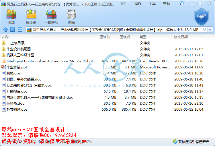
两足行走机器人—行走结构部分设计【优秀含16张CAD图纸+全套机械毕业设计】.zip
行走结构部分设计审题表.doc---(点击预览)
毕业答辩.ppt---(点击预览)
开题报告.doc---(点击预览)
封面、中外文摘要.doc---(点击预览)
外文翻译.doc---(点击预览)
初稿.doc---(点击预览)
任务书.doc---(点击预览)
两足行走机器人——行走结构部分设计.doc---(点击预览)
Intelligent Control of an Autonomous Mobile Robot using Type-2 Fuzzy Logic.pdf---(点击预览)
机器人三维设计图
asm0001.asm.2
asm0001.asm.3
asm0001.asm.4
asm0003.asm.10
asm0003.asm.11
asm0003.asm.12
asm0003.asm.9
asm0004.asm.9
asm0005.asm.10
asm0005.asm.6
asm0005.asm.7
asm0005.asm.8
asm0005.asm.9
asm0006.asm.10
asm0006.asm.11
asm0006.asm.12
asm0006.asm.7
asm0006.asm.8
asm0006.asm.9
asm0007.asm.2
asm0009.asm.2
asm0010.asm.4
asm0010.asm.5
asm0010.asm.6
asm0011.asm.4
asm0011.asm.5
current_session.pro
drw0001_dwg__out.log.1
drw0001_dwg__out.log.2
drw0002_dwg__out.log.1
drw0002_dwg__out.log.2
drw0002_dwg__out.log.3
drw0003_dwg__out.log.1
drw0003_dwg__out.log.2
drw0003_dwg__out.log.3
drw0004_dwg__out.log.1
drw0005_dwg__out.log.1
drw0005_dwg__out.log.2
drw0007_dwg__out.log.1
drw0008_dwg__out.log.1
drw0009_dwg__out.log.1
drw0010_dwg__out.log.1
drw0011_dwg__out.log.1
prt0001.prt.13
prt0002.prt.9
prt0003.prt.10
prt0003.prt.11
prt0003.prt.12
prt0003.prt.7
prt0003.prt.8
prt0003.prt.9
prt0004.prt.11
prt0004.prt.12
prt0004.prt.13
prt0005.prt.9
prt0006.prt.12
prt0006.prt.13
prt0006.prt.14
prt0006.prt.15
prt0006.prt.16
prt0006.prt.17
prt0007.prt.12
prt0008.prt.4
prt0008.prt.5
prt0008.prt.6
prt0009.prt.11
prt0009.prt.12
prt0009.prt.13
prt0010.prt.6
prt0011.prt.5
prt0011.prt.6
prt0011.prt.7
prt0012.prt.4
prt0014.prt.2
prt0014.prt.3
trail.txt.1
trail.txt.2
毕业设计装配图
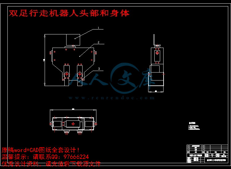
双足行走机器人头部和身体.dwg
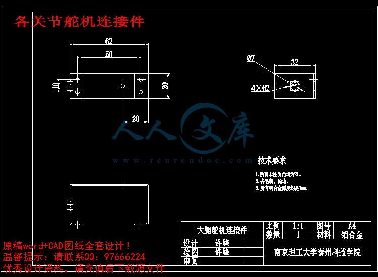
各关节舵机连接件.dwg
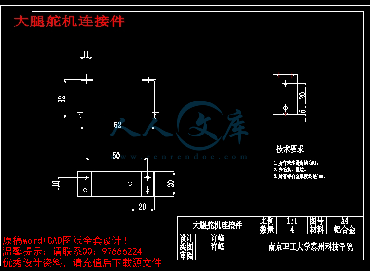
大腿舵机连接件.dwg
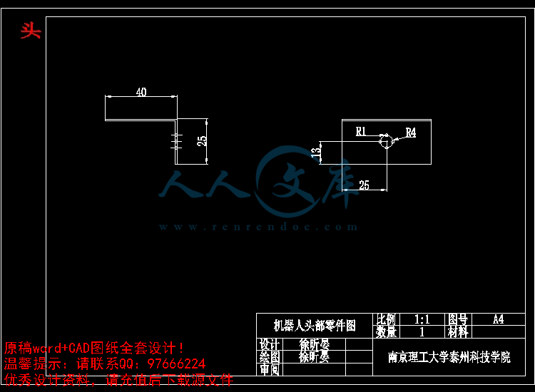
头.dwg
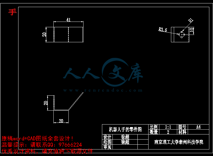
手.dwg
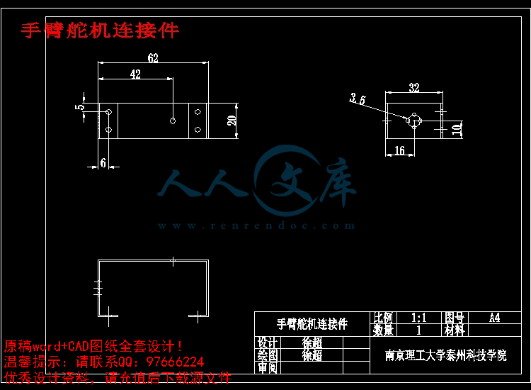
手臂舵机连接件.dwg
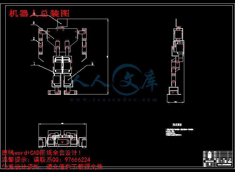
机器人总装图.dwg
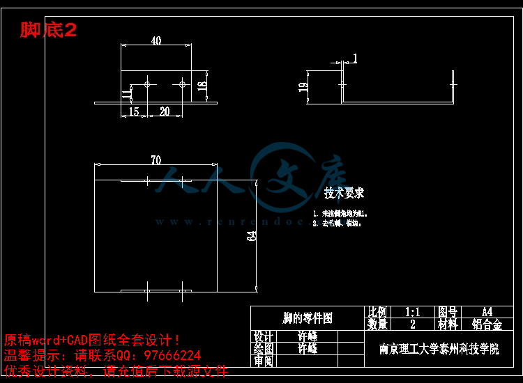
脚底2.dwg
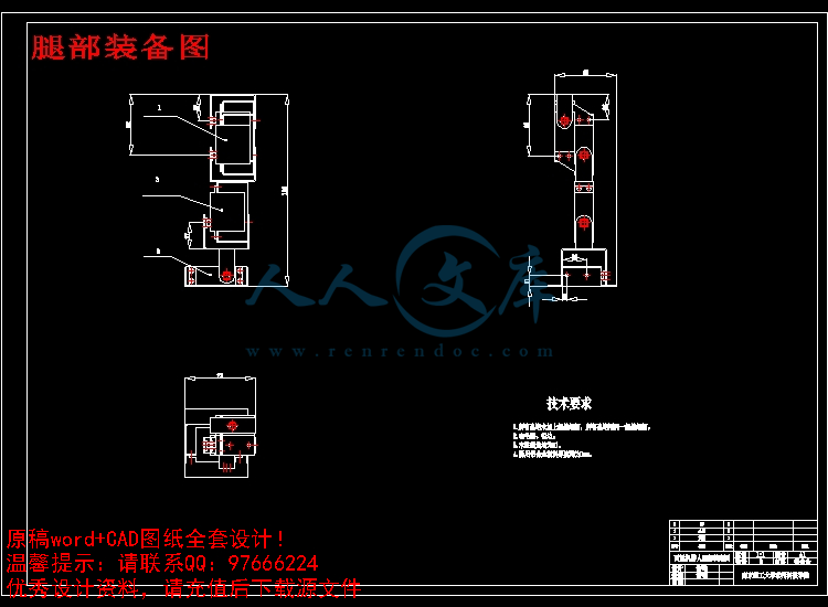
腿部装备图.dwg
臂部装配图.dwg
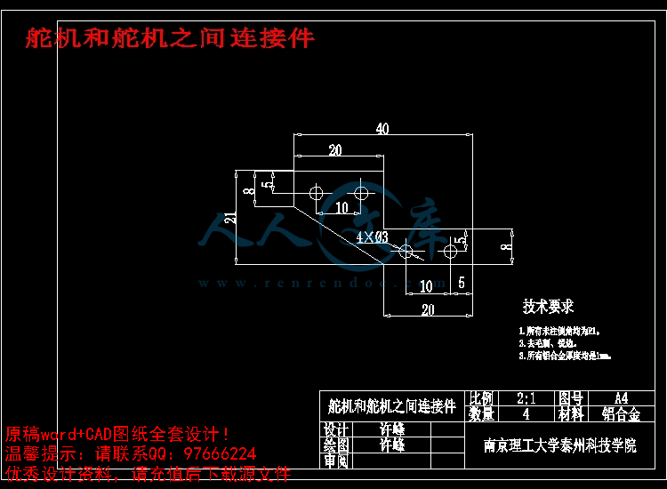
舵机和舵机之间连接件.dwg
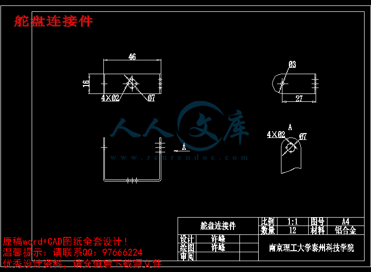
舵盘连接件.dwg
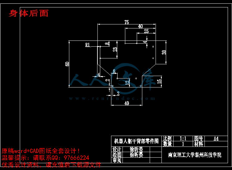
身体后面.dwg
身体和腿部连接件.dwg
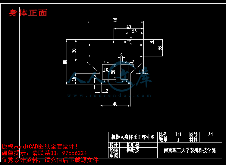
身体正面.dwg
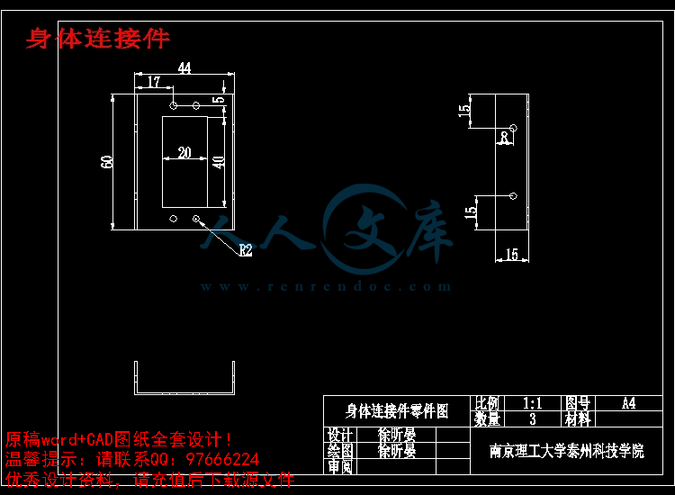
身体连接件.dwg
压缩包内文档预览:(预览前20页/共26页)
预览图 预览图 预览图 预览图 预览图 预览图 预览图 预览图 预览图 预览图 预览图 预览图 预览图 预览图 预览图 预览图 预览图 预览图 预览图 预览图
编号:457624    类型:共享资源    大小:14.92MB    格式:ZIP    上传时间:2015-07-17 上传人:小*** IP属地:福建
50
积分
关 键 词:
行走 机器人 结构 部分 部份 设计 优秀 优良 16 cad 图纸 全套 机械 毕业设计
资源描述:

!【详情如下】CAD图纸+word设计说明书.doc[10000字,24页]【需要咨询购买全套设计请加QQ97666224】.bat

两足行走机器人——行走结构部分设计.doc

任务书.doc

初稿.doc

外文翻译.doc

封面、中外文摘要.doc

开题报告.doc

毕业答辩.ppt

行走结构部分设计审题表.doc

双足行走机器人头部和身体.dwg

各关节舵机连接件.dwg

大腿舵机连接件.dwg

头.dwg

手.dwg

手臂舵机连接件.dwg

机器人总装图.dwg

脚底2.dwg

腿部装备图.dwg

臂部装配图.dwg

舵机和舵机之间连接件.dwg

舵盘连接件.dwg

身体后面.dwg

身体和腿部连接件.dwg

身体正面.dwg

身体连接件.dwg

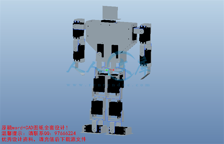
机器人三维设计图


毕业设计说明书(论文)中文摘要


20世纪40年代,伴随着遥控操纵器和数控制造技术的出现,关于机器人技术的研究开始出现。经过几十年的发展,数百种不同结构、不同控制系统、不同用途的机器人已进入了实用化阶段。目前,机器人大多以轮子的形式实现行走功能阶段。真正模仿人类用腿走路的机器人还不多,虽有一些六足、四足机器人涌现,但是两足机器人还是凤毛麟角。本课题主要针对两足机器人的行走进行研究、分析、设计,然后材料加工制作,最后进行组装和行走调试。


关键词  研究  设计  制作


毕业设计说明书(论文)外文摘要


Title          The Robot Move with Two-legs                  


             — Designing of Stepped  Structure                                                


Abstract

In 1940s, along with the remote control and digital manufacturing technologies, the researches on robot technology were appeared. After decades of development, hundreds of different structures, different control systems, and different uses of the robots have been entered into a practical stage. At present, most robots use   wheel to realize the function phase of walking. But there is little robot can imitate human walking that with two legs , although a number of six-legged, four-legged robots have emerged, two-legged robots are rare. So the main topics of this  study is to research, analysis and design on the two-legged walking robot, and product materials, then set up them and do some adjustment through walking in the final.


Keywords  research  design  facture

目   录


1  绪论1

1.1  引言1

1.2  机器人的发展及技术1

1.3  两足机器人的优点及国内外研究概况2

1.4  本课题的主要工作7

2  双足机器人本体结构设计分析8

2.1  引言8

2.2  两足机器人的结构分析8

2.3  机器人设计思路9

2.4  机器人设计方案10

2.5  驱动方式的选择12

3  双足机器人的具体制作13

3.1  双足机器人的材料选择13

3.2  双足机器人的零件加工13

3.3  两足机器人的组装16

3.4  两足机器人相关数据19

3.5  两足机器人总体尺寸19

3.6  舵机具体参数19

4  课题总结20

结束语21

致谢22

参考文献23


1  绪论

1.1  引言

目前,机器人已形成一个不同技术层次、应用于多种环境的“庞大”家族,从天上到地下,从陆地到海洋到处都可以看到机器人的身影。世界著名机器人专家,日本早稻田大学的加藤一郎教授曾经指出“机器人应当具有的最大的特征之一是步行功能”。步行机器人的研究涉及到多门学科的交叉融合,如仿生学、机构学、控制理论与工程学、电子工程学、计算机科学及传感器信息融合等。仿人形机器人正成为机器人研究中的一个热点,其研究水平,在一定程度上代表了一个国家的高科技发展水平和综合实力。研究仿人形双足步行机器人,除了具有重要的学术意义,还有现实的应用价值。

参 考 文 献


[1]  周远清,张再兴等编著. 智能机器人系统[M]. 北京: 清华大学出版社,1989.

[2]  蒋新松主编. 机器人学导论[M]. 沈阳: 辽宁科学技术出版社,1994.

[3]  方建军,何广平. 智能机器人[M]. 北京:化学工业出版社,2004.

[4]  张永学. 双足机器人步态规划及步行控制研究[D]. 哈尔滨工业大学博士学位论文. 2001.

[5]  刘志远. 两足机器人动态行走研究[D]. 哈尔滨工业大学博士论文. 1991.

[6]  刘志远,戴绍安,裴润,张栓,傅佩深. 零力矩点与两足机器人动态行走稳定性的关系[N]. 哈尔滨工业大学学报. 1994.

[7]  纪军红. HIT-Ⅱ双足步行机器人步态规划研究[D]. 哈尔滨工业大学博士论文,2000.

[8]  麻亮,纪军红,强文义,傅佩深. 基于力矩传感器的双足机器人在线模糊步态调整器设计[R]. 2000.

[9]  竺长安. 两足步行机器人系统分析、设计及运动控制[D]. 国防科技大学博士论文. 1992.

[10] 马宏绪. 两足步行机器人动态步行研究[D]. 国防科技大学博士论文. 1995.

[11] 包志军. 仿人型机器人运动特性研究[D]. 上海交通大学博士论文. 2000.

[12] 孙富春,朱纪洪,刘国栋等. 机器人学导论-分析、系统及应用[M]. 北京:电子工业出版社,2004.

[13] 柳洪义,宋伟刚. 机器人技术基础[M]. 北京:冶金工业出版社,2002

[14] 刘晋春,白基成,郭永丰. 特种加工[M]. 北京:机械工业出版社,2008.3.

[15] 解仑,王志良,李华俊.双足步行机器人制作技术[M]. 北京:机械工业出版社,2008.4.

内容简介:
南京理工大学泰州科技学院 毕业设计 (论文 )外文资料翻译 系 部: 机械工程系 专 业: 机械工程及自动化 姓 名: 许峰 学 号: 05010245 外文出处: Advance online publication: 4 August 2006 附 件: 1.外文资料翻译译文; 2.外文原文。 指导教师评语: 该生的外文翻译基本正确, 没有严重的语法或拼写错误,已达到本科毕业的水平。 签名: 年 月 日 nts附件 1:外文资料翻译译文 对移动式遥控装置的智能控制 使用 2型模糊理论 摘要:我们针对单轮移动式遥控装置的动态模型开发 出一种追踪控制器,这种追踪控制器是建立在模糊理论的基础上将运动控制器和力矩控制器整合起来的装置。用计算机模拟来确定追踪控制器的工作情况和它对不同航向的实际用途。 关键词:智能控制、 2型模糊理论、移动式遥控装置 I. 介绍 由于受运动学强制约束,移动遥控装置是非完整的系统。描述此约束的恒等式不能够明确的反映出遥控装置在局部及整体坐标系中的关系。因此,包括它们在内的控制问题吸引了去年控制领域的注意力。 不同的方法被用来解决运动控制的问题。 Kanayama等人针对一个非完整的交通工具提出了一个稳定的追踪控制方案, 这种方案使用了 Lyapunov功能。 Lee等人用还原法和饱和约束来解决追踪控制。此外,大多数被报道过的设计依赖于智能控制方式如模糊逻辑控制和神经式网络。 然而上述提到的发表中大多数都集中在移动式遥控装置的运动模块,即这些模块是受速度控制的。而很少有发表关注到不完整的动力系统,即受力和扭矩控制的模块:布洛克。 在 2005年 12月 15日被视为标准并且在 2006年 3月 5日被公认的手稿。这一著作在某种程度上受到 DGEST 一个在 Grant 493.05-P下的研究所的支持。研究者们同样也受到了来自 CONACYT 给予他们研究成果的奖学金的支持。 在这篇论文中我展现了一台追踪单轮移动式遥控装置的控制器,这台追踪控制器用了一种控制条件如移动遥控装置的速度达到了有效速度,还用了一种模糊理论控制器如给实际遥控装置提供了必要扭矩。这篇论文的其余部分的结构如下:第二部分和第三部分对问题作了简洁描述,包括了单轮车移动遥控装置的运动和动力模块和对追踪控制器的介绍。第四部分用追踪控制器列举了些模拟结果。第五部分做出了结论。 ntsII. 疑难问题陈述 A移动控制装置 这个被看作单轮移动控制器的模型(见图 1),它是由两个同轴驱动轮和一个自由前轮组成。 图 1. 旋转移动机械手 运动规律可见平面 5的运动方程式 q&=0sincos000wv M(q)&+V(q,q)v+G(q)= (1) q= ,yx T q是描述控制器位置的坐标矢量,( x, y)是笛卡尔坐标,它指出了构件的移动中心, 是 构件朝向和 x轴之间的夹角(夹角为逆时针形式); v为速度矢量, v 和 w分别为长度和角速度 ; 为输入矢量, M是一个对称的正定义的固定零件, R是一个向心的零件 ,G是重力矢量。等式( 1, a)表示移动控制装置的运动或驾驶系统。注意到防滑条件强加了一个不完整的约束,也就是说这个移动控制装置只能够朝着驱动轮轴线的方向移动。 ycos -xsin =0 (2) 移动遥控装置式的追踪控制器构造如下:一条特定的预想轨迹 q和移动遥控 装置的方向,我们必须设计出一个控制器使其适用于合适的扭矩诸如测定的位置达到参考位置(由 3式表示)。 0)(lim tqq dt ( 3) 为了达到控制目标,我们基于 5的步骤,我们得到 (t) 利用模糊逻辑控制器nts( FLC)控制着轮系 (1.a)。追踪控制器的大体结构见图 2 III.运动模块的控制 我们基于 Kanayama等人提议的程序和 Nelson等人解决运动模块的追踪问题,这由 V表示出来。假设轨迹 q达到了( 4)式的要求: qd=0sincosdd100ddwv (4) 用遥控器的局部框架(图 1中的移动坐标系),错误的坐标可被定义为: e=Te(qd-q),eeeyx =1000c oss in0s inc os = dddyyxx (5) 辅助速度控制着输入量,其可以对( 1, a)实现追踪。表示如 下: vc=fc(e,vd),ccwv = ekvekww ekevdyddxd s inc o s321 (6) 其中 k1, k2 and k3是连续的正整数 IV.模糊逻辑控制器 模糊逻辑控制器的目的是找出控制输入量 如实际速度矢量 v和速度矢量 vc之间的关系 0vlim vdt ( 7) 就像图 2中所显示的一样,根本上说 FLC有两 个输入变量相应的引出两个速度错误,分别是长度和角度,且两个输出变量,驱动和旋转输入扭矩,分别为 F和 N,他们的作用分别是 1的所有直角和 2的梯形,且很容易被估算出来。 图 3和图 4描绘了 N,C,P代表的模糊方框中的 MFS结合了每一个输入和输出变量,这些变量都被包括在范围 -1,1中 图 2. 追踪控制结构 nts 图 3. 输入可变电压 ev 和 ew 图 4. 输出的 F和 N FLC中包含 9条控制着输入和输出关系的直线,这采用了 Mamdani形式的推论引擎,我们利用了万有引力中心的方法来实现非模糊程序。在表格 1中,我们表现了一种直线形式: Rule i: 假如 ev 是 G1 , ew 是 G2 那么 F 是 G3 , N 是 G4 Where G1.G4 are the fuzzy set associated to each variable and i= 1 . 9. 表 1 模糊尺组 In Table I, N means NEGATIVE, P means POSITIVE and C means ZERO. V.模拟结果 在 Matalb实现的模拟实验是用来测试移动式遥控装置的追踪控制器(在( 1)nts中已有定义 )。我们认为初始位置 q和 初始速度 v。在图 5到图 8中,我们体现了对于情况 1的模拟结果。位置和方向错误分别见图 5和图 6,错误可近似于零。追踪轨迹(见图 7)也和预想的及其接近,速度错误(见图 8)减小至 0,达到了整个模拟过程中 1秒内的控制目标。图 9是测试控制器的模拟简图。图 10是三个变量的追踪错误。最后,图 11是遗传运算法则的演化过程,这个通常用来查找模糊控制器的最佳参数。 图 5.位置错误参量值。(直线为 x,虚线为 y) nts 图 6.方向错误参量值 图 7.移动遥控装置运动轨迹 nts 图 8. 速度错误 : 实线 : 错误在 e, 虚线 :错误在 evw 图 9 控制器的模拟板块 nts 图 10三个变量的跟踪错误 图 11 查找最优的方案仿真 表 2为模糊控制器在 25个在不同环境下所产生的模拟结果。从这个表中我们同样选择了不同的速度和位置参数 nts 表 2 不同模糊控制器实验仿真 VI.总结 追踪控制器是将单轮移动遥控装置的模糊逻辑控制器与可测定点的稳定性和速度轨迹的动力学整合起来的。计算机模拟结果确定了这台控制器可以实现我们的目标。在以后的工作中,图 2中的控制结构可以做些扩展,比如说增加些跟踪的准确性或工 作性能。 nts附件 2:外文原文 Intelligent Control of an Autonomous Mobile Robot using Type-2 Fuzzy Logic Abstract We develop a tracking controller for the dynamic model of unicycle mobile robot by integrating a kinematic controller and a torque controller based on Fuzzy Logic Theory. Computer simulations are presented confirming the performance of the tracking controller and its application to different navigation problems. Index Terms Intelligent Control, Type-2 Fuzzy Logic, Mobile Robots. I. INTRODUCTION Mobile robots are nonholonomic systems due to the constraints imposed on their kinematics. The equations describing the constraints cannot be integrated simbolically to obtain explicit relationships between robot positions in local and global coordinates frames. Hence, control problems involve them have attracted attention in the control community in the last years 11. Different methods have been applied to solve motion control problems. Kanayama et al. 10 propose a stable tracking control method for a nonholonomic vehicle using a Lyapunov function. Lee et al. 12 solved tracking control using backstepping and in 13 with saturation constraints. Furthermore, most reported designs rely on intelligent control approaches such as Fuzzy Logic Control 1814171820 and Neural Networks 619. However the majority of the publications mentioned above, has concentrated on kinematics models of mobile robots, which are controlled by the velocity input, while less attention has been paid to the control problems of nonholonomic dynamic systems, where forces and torques are the true inputs: Bloch Manuscript received December 15, 2005 qnd accepted on April 5, 2006. This work was supported in part by the Research Council of DGEST under Grant nts493.05-P. The students also were supported by CONACYT with scholarships for their graduate studies. Oscar Castillo is with the Division of Graduate Studies and Research in Tijuana Institute of Technology, Mexico (corresponding author phone: 52664-623-6318; fax: 52664-623-6318; e-mail: ocastillotectijuana.mx). Patricia Melin is with the Division of Graduate Studies and Research in Tijuana Institute of Technology, Mexico (e-mail: hariastectijuana.mx). Arnulfo Alanis is with the Division of Graduate Studies and Research in Tijuana Institute of Technology, Mexico (e-mail: pmelintectijuana.mx) Leslie Astudillo is a graduate student in Computer Science with the Division of Graduate Studies and Research in Tijuana Institute of Technology, Mexico (e-mail: pmelintectijuana.mx) Jose Soria is a with the Division of Graduate Studies and Research in Tijuana Institute of Technology, Mexico (e-mail: jsoria). Luis Aguilar is with CITEDI-IPN Tijuana, Mexico(e-mail:laguilarcitedi.mx) and Drakunov 2 and Chwa 4, used a sliding mode control to the tracking control problem. Fierro and Lewis 5 propose a dynamical extension that makes possible the integration of kinematic and torque controller for a nonholonomic mobile robot. Fukao et al. 7, introduced an adaptive tracking controller for the dynamic model of mobile robot with unknown parameters using backstepping. In this paper we present a tracking controller for the dynamic model of a unicycle mobile robot, using a control law such that the mobile robot velocities reach the given velocity inputs, and a fuzzy logic controller such that provided the required torques for the actual mobile robot. The rest of this paper is organized as follows. Sections II and III describe the formulation problem, which include: the kinematic and dynamic model of the unicycle mobile robot and introduces the tracking controller. Section IV illustrates the simulation results using the tracking controller. The ntssection V gives the conclusions. II. PROBLEM FORMULATION A. The Mobile Robot The model considered is a unicycle mobile robot (see Fig. 1), it consist of two driving wheels mounted on the same axis and a front free wheel 3. Fig. 1. Fig. 1. Wheeled mobile robot. The motion can be described with equation (1) of movement in a plane 5: Q&=0sincos000wv M(q)&+V(q,q)v+G(q)= (1) Where q= ,yx T is the vector of generalized coordinates which describes the robot position, (x,y) are the cartesian coordinates, which denote the mobile center of mass and is the angle between the heading direction and the x-axis(which is taken counterclockwise form);v= w,v T is the vector of velocities, v and w are the linear and angular velocities respectively; rR is the input vector,M(q) Rnxn is a symmetric and positive-definite inertia matrix, V(q,q) Rnxn is the centripetal and Coriolis matrix,G(q) Rn is the ntsgravitational vector. Equation (1.a) represents the kinematics or steering system of a mobile robot. Notice that the no-slip condition imposed a non-holonomic constraint described by (2), that it means that the mobile robot can only move in the direction normal to the axis of the driving wheels. ycos -xsin =0 (2) B. Tracking Controller of Mobile Robot Our control objective is established as follows: Given a desired trajectory qd(t) and orientation of mobile robot we must design a controller that apply adequate torque such that the measured positions q(t) achieve the desired reference qd(t) represented as (3): 0)(lim tqq dt ( 3) To reach the control objective, we are based in the procedure of 5, we deriving a (t) of a specific v c(t) that controls the steering system (1.a) using a Fuzzy Logic Controller (FLC). A general structure of tracking control system is presented in the Fig. 2. III. CONTROL OF THE KINEMATIC MODEL We are based on the procedure proposed by Kanayama et al. 10 and Nelson et al. 15 to solve the tracking problem for the kinematic model, this is denoted as vc(t). Suppose the desired trajectory qd satisfies (4): qd=0sincosdd100ddwv (4) Using the robot local frame (the moving coordinate system x-y in figure 1), the error coordinates can be defined as (5): e=Te(qd-q),eeeyx =1000c oss in0s inc os = dddyyxx (5) And the auxiliary velocity control input that achieves tracking for (1.a) is given by (6): ntsvc=fc(e,vd),ccwv = ekvekww ekevdyddxd s inc o s321 (6) Where k1, k2 and k3 are positive constants. IV. FUZZY LOGIC CONTROLLER The purpose of the Fuzzy Logic Controller (FLC) is to find a control input such that the current velocity vector v to reach the velocity vector vc this is denoted as (7): 0vlim vdt ( 7) As is shown in Fig. 2, basically the FLC have 2 inputs variables corresponding the velocity errors obtained of (7) (denoted as ev and ew: linear and angular velocity errors respectively), and 2 outputs variables, the driving and rotational input torques (denoted by F and N respectively). The membership functions (MF)9 are defined by 1 triangular and 2 trapezoidal functions for each variable involved due to the fact are easy to implement computationally. Fig. 3 and Fig. 4 depicts the MFs in which N, C, P represent the fuzzy sets 9 (Negative, Zero and Positive respectively) associated to each input and output variable, where the universe of discourse is normalized into -1,1 range. Fig. 2. Tracking control structure nts Fig. 3. Membership function of the input variables ev and ew Fig. 4. Membership functions of the output variables F and N. The rule set of FLC contain 9 rules which governing the input-output relationship of the FLC and this adopts the Mamdani-style inference engine 16, and we use the center of gravity method to realize defuzzification procedure. In Table I, we present the rule set whose format is established as follows: Rule i: If ev is G1 and ew is G2 then F is G3 and N is G4 Where G1.G4 are the fuzzy set associated to each variable and i= 1 . 9. TABLE 1 FUZZY RULE SET ntsIn Table I, N means NEGATIVE, P means POSITIVE and C means ZERO. V. SIMULATION RESULTS Simulations have been done in Matlab to test the tracking controller of the mobile robot defined in (1). We consider the initial position q(0) = (0, 0, 0) and initial velocity v(0) = (0,0). From Fig. 5 to Fig. 8 we show the results of the simulation for the case 1. Position and orientation errors are depicted in the Fig. 5 and Fig. 6 respectively, as can be observed the errors are sufficient close to zero, the trajectory tracked (see Fig. 7) is very close to the desired, and the velocity errors shown in Fig. 8 decrease to zero, achieving the control objective in less than 1 second of the whole simulation. We show in Fig. 9 the Simulink block diagram to test the controller. We also show in Fig. 10 the tracking errors in the three variables. Finally, we show in Fig. 11 the evolution of the genetic algorithm that was used to find the optimal parameters for the fuzzy controller. Fig. 5. Positions error with respect to the reference values. Solid: error in x, dotted: error in y. nts Fig. 6. Orientation error with respect to the reference values. Fig. 7. Mobile Robot Trajectory. nts Fig. 8. Velocity errors: Solid: error in e, dotted: error in evw Fig. 9 Simulink block diagram of the controller. nts Fig. 10 Tracking errors in the three variables. nts Fig. 11 Evolution of GA for finding optimal Controller In Table II we show simulation results for 25 experiments with different conditions for the gains of the fuzzy controller. We can also appreciate from this table that different reference velocities and positions were considered. TABLE II SIMULATION RESULTS FOR DIFFERENT EXPERIMENTS WITH THE FUZZY CONTROLLER. VI. CONCLUSIONS We described the development of a tracking controller integrating a fuzzy logic controller for a unicycle mobile robot with known dynamics, which can be applied for both, point stabilization and trajectory tracking. Computer simulation results confirm that the controller can achieve our objective. As future work, several extensions can be made to the control ntsstructure of Fig. 2, such as to increase the tracking accuracy and the performance level. REFERENCES 1 S. Bentalba, A. El Hajjaji, A. Rachid, Fuzzy Control of a Mobile Robot: A New Approach, Proc. IEEE Int. Conf. On Control Applications, Hartford, CT, pp 69-72, October 1997. 2 A. M. Bloch, S. Drakunov, Tracking in NonHolonomic Dynamic System Via Sliding Modes, Proc. IEEE Conf. On Decision & Control, Brighton, UK, pp 1127-1132, 1991. 3 G. Campion, G. Bastin, B. DAndrea -Novel, Structural Properties and Classification of Kinematic and Dynamic Models of Wheeled Mobile Robots, IEEE Trans. On Robotics and Automation, Vol. 12, No. 1, February 1996. 4 D. Chwa., Sliding-Mode Tracking Control of Nonholonomic Wheeled Mobile Robots in Polar coordinates, IEEE Trans. On Control Syst. Tech. Vol. 12, No. 4, pp 633-644, July 2004. 5 R. Fierro and F.L. Lewis, Control of a Nonholonomic Mobile Robot: Backstepping Kinematics into Dynamics. Proc. 34th Conf. on Decision & Control, New Orleans, LA, 1995. 6 R. Fierro, F.L. Lewis, Control of a Nonholonomic Mobile Robot Using Neural Networks, IEEE Trans. On Neural Networks, Vol. 9, No. 4, pp 589 600, July 1998. 7 T. Fukao, H. Nakagawa, N. Adachi, Adaptive Tracking Control of a NonHolonomic Mobile Robot, IEEE Trans. On Robotics and Automation, Vol. 16, No. 5, pp. 609-615, October 2000. 8 S. Ishikawa, A Method of Indoor Mobile Robot Navigation by Fuzzy Control, Proc. Int. Conf. Intell. Robot. Syst., Osaka, Japan, pp 1013-1018, 1991. 9 J. S. R. Jang, C.T. Sun, E. Mizutani, Neuro Fuzzy and Soft Computing: A Computational Approach to Learning and Machine Intelligence, ntsPrentice Hall, Upper Sadle River, NJ, 1997. 10 Y. Kanayama, Y. Kimura, F. Miyazaki T. Noguchi, A Stable Tracking Control Method For a Non-Holonomic Mobile Robot, Proc. IEEE/RSJ Int. Workshop on Intelligent Robots and Systems, Osaka, Japan, pp 1236- 1241, 1991. 11 I. Kolmanovsky, N. H. McClamroch., Developments in Nonholonomic Nontrol Problems, IEEE Control Syst. Mag., Vol. 15, pp. 20 36, December. 1995. 12 T-C Lee, C. H. Lee, C-C Teng, Tracking Control of Mobile Robots Using the Backsteeping Technique, Proc. 5th. Int. Conf. Contr., Automat., Robot. Vision, Singapore, pp 1715-1719, December 1998. 13 T-C Lee, K. Tai, Tracking Control of Unicycle-Modeled Mobile robots Using a Saturation Feedback Controller, IEEE Trans. On Control Systems Technology, Vol. 9, No. 2, pp 305-318, March 2001. 14 T. H. Lee, F. H. F. Leung, P. K. S. Tam, Position Control for Wheeled Mobile Robot Using a Fuzzy Controller, IEEE pp 525-528, 1999. 15 W. Nelson, I. Cox, Local Path Control for an Autonomous Vehicle, Proc. IEEE Conf. On Robotics and Automation, pp. 1504-1510, 1988. 16 K. M. Passino, S. Yurkovich, “Fuzzy Control”, Addison Wesley Longman, USA 1998. 17 S. Pawlowski, P. Dutkiewicz, K. Kozlowski, W. Wroblewski, Fuzzy Logic Implementation in Mobile Robot Control, 2nd Workshop On Robot Motion and Control, pp 65-70, October 2001. 18 C-C Tsai, H-H Lin, C-C Lin, Trajectory Tracking Control of a Laser-Guided Wheeled Mobile Robot, Proc. IEEE Int. Conf. On Control Applications, Taipei, Taiwan, pp 1055-1059, September 2004. 19 K. T. Song, L. H. Sheen, Heuristic fuzzy-neural Network and its application to reactive navigation of a mobile robot, Fuzzy Sets Systems, Vol. 110, No. 3, pp 331-340, 2000. 20 S. V. Ulyanov, S. Watanabe, V. S. Ulyanov, K. Yamafuji, L. V. ntsLitvintseva, G. G. Rizzotto, Soft Computing for the Intelligent Robust Control of a Robotic Unicycle with a New Physical Measure for Mechanical Controllability, Soft Computing 2 pp 73 88, Springer- Verlag, 1998. Oscar Castillo is a Professor of Computer Science in the Graduate Division, Tijuana Institute of Technology, Tijuana, Mexico. In addition, he is serving as Research Director of Computer Science and head of the research group on fuzzy logic and genetic algorithms. Currently, he is President of HAFSA (Hispanic American Fuzzy Systems Association) and Vice-President of IFSA (International Fuzzy Systems Association) in charge of publicity. Prof. Castillo is also Vice-Chair of the Mexican Chapter of the Computational Intelligence Society (IEEE). Prof. Castillo is also General Chair of the IFSA 2007 World Congress to be held in Cancun, Mexico. He also belongs to the Technical Committee on Fuzzy Systems of IEEE and to the Task Force on “Extensions to Type -1 Fuzzy Systems”. His research interests are in Type -2 Fuzzy Logic, Intuitionistic Fuzzy Logic, Fuzzy Control, Neuro-Fuzzy and Genetic-Fuzzy hybrid approaches. He has published over 50 journal papers, 5 authored books, 10 edited books, and 160 papers in conference proceedings. nts Patricia Melin is a Professor
温馨提示:
1: 本站所有资源如无特殊说明,都需要本地电脑安装OFFICE2007和PDF阅读器。图纸软件为CAD,CAXA,PROE,UG,SolidWorks等.压缩文件请下载最新的WinRAR软件解压。
2: 本站的文档不包含任何第三方提供的附件图纸等,如果需要附件,请联系上传者。文件的所有权益归上传用户所有。
3.本站RAR压缩包中若带图纸,网页内容里面会有图纸预览,若没有图纸预览就没有图纸。
4. 未经权益所有人同意不得将文件中的内容挪作商业或盈利用途。
5. 人人文库网仅提供信息存储空间,仅对用户上传内容的表现方式做保护处理,对用户上传分享的文档内容本身不做任何修改或编辑,并不能对任何下载内容负责。
6. 下载文件中如有侵权或不适当内容,请与我们联系,我们立即纠正。
7. 本站不保证下载资源的准确性、安全性和完整性, 同时也不承担用户因使用这些下载资源对自己和他人造成任何形式的伤害或损失。
提示  人人文库网所有资源均是用户自行上传分享,仅供网友学习交流,未经上传用户书面授权,请勿作他用。
关于本文
本文标题:两足行走机器人—行走结构部分设计【带三维】【优秀含16张CAD图纸+全套机械毕业设计】
链接地址:https://www.renrendoc.com/p-457624.html

官方联系方式

2:不支持迅雷下载,请使用浏览器下载   
3:不支持QQ浏览器下载,请用其他浏览器   
4:下载后的文档和图纸-无水印   
5:文档经过压缩,下载后原文更清晰   
关于我们 - 网站声明 - 网站地图 - 资源地图 - 友情链接 - 网站客服 - 联系我们

网站客服QQ:2881952447     

copyright@ 2020-2024  renrendoc.com 人人文库版权所有   联系电话:400-852-1180

备案号:蜀ICP备2022000484号-2       经营许可证: 川B2-20220663       公网安备川公网安备: 51019002004831号

本站为文档C2C交易模式,即用户上传的文档直接被用户下载,本站只是中间服务平台,本站所有文档下载所得的收益归上传人(含作者)所有。人人文库网仅提供信息存储空间,仅对用户上传内容的表现方式做保护处理,对上载内容本身不做任何修改或编辑。若文档所含内容侵犯了您的版权或隐私,请立即通知人人文库网,我们立即给予删除!