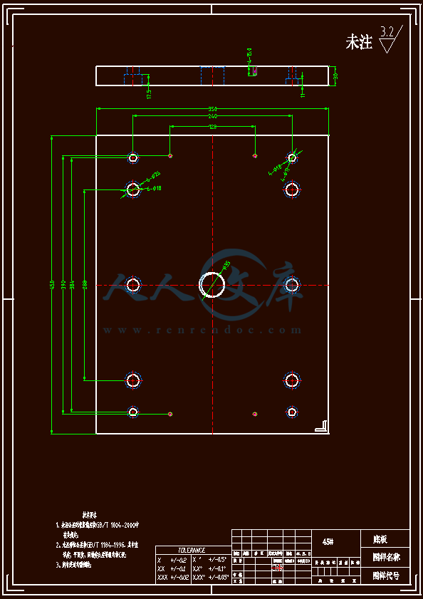
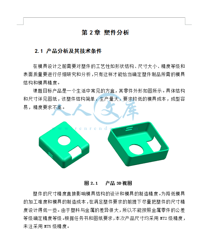
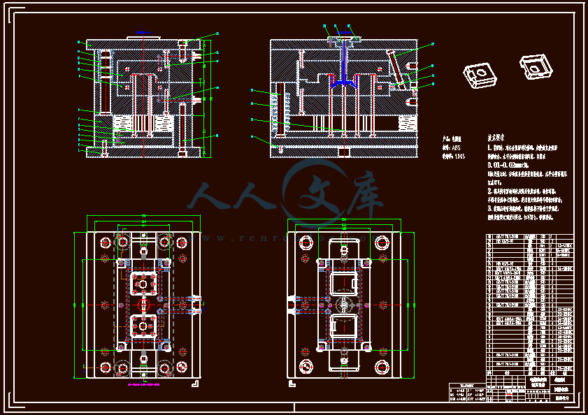
电器盖注塑模具设计【全套含有CAD图纸三维UG建模】
收藏
资源目录

压缩包内文档预览:(预览前20页/共43页)
编号:6117535
类型:共享资源
大小:9.04MB
格式:ZIP
上传时间:2017-11-21
上传人:机****料
认证信息
个人认证
高**(实名认证)
河南
IP属地:河南
50
积分
- 关 键 词:
-
电器
注塑
模具设计
全套
含有
cad
图纸
三维
ug
建模
- 资源描述:
-


- 内容简介:
-
English translation in injection moldAbstract: According to the requirements of the plastic products,understand the use of plastic parts, technical requirements, analysis ofdimensional accuracy and other technical considerations of plasticparts, plastic parts size. We used a mold two cavity, the side gate,injection machine uses the Haitian 110X 1A models, equipped with acooling system, CAD and UG drawing two-dimensional assemblydrawing and parts drawing, choose the reasonable processing methodof mould. Attach a statement, the systematic use of a brief text,analysis and calculation of plastic parts and concise, so as to makereasonable mold design.Key Words : Mechanical design; mold design; CAD UG to drawthe 3D drawing two-dimensional map.1、IntroductionMany types of mold, the structure and varieties of plastic, plasticinjection molding machine and the complexity of the types and otherfactors, its basic structure is composed of the movable mould and thefixed mould is composed of two parts. The fixed mould part arrangedon the fixing plate of the machine, dynamic part is installed in themobile injection molding machine, in the injection molding processwith the clamping system of injection molding machines movement.Part of mold and die part guided by a guide post and a closeddynamic injection molding. General injection molding parts, theclamping mechanism, gating system, side parting and core pullingmechanism, pushing mechanism, a heating and cooling system,exhaust system and the supporting parts.At present, the mould manufacturing technology in China hasbeen from the past can only make simple mold to mold can producelarge, sophisticated, complex, long life. In the plastic mold design andmanufacturing, to bumper and the whole panel of large injectionmold. With the rapid development of computer technology, the molddesign and manufacturing technology is moving in the direction ofthe development of digital. On the one hand, the domestic marketwill continue to mold growth; on the other hand, mold manufacturingis gradually transferred to China and the multinational corporations toChinas purchases tend to die is also very obvious. Chinas economy isstill in a stage of rapid development, the international developmenttrend of economic globalization is increasingly obvious, whichprovides good conditions and opportunities for the rapiddevelopment of mold industry in our country.2、 Mold-Filling Simulation2.1 Calculation of the interface locationsThe mold filling velocity and the shape of the melt front in LFCare quite different from those in the conventional empty moldcasting The velocity at the melt front is restricted by the foamdegradation , gas elimination , pressure building-up in themold , etc , and 1t is affected by the original processparameters,such as the vacuum degree,the pattern density and themetallic static head The meltpattern interface develops in aradiate mannerDue to the foam degradation caused by the heattransfer between the molten metal and the foam pattern in LFCTheinfluence of the gravity on the mold filling velocity and the interfacemorphology in LFC is minor compared with that in the conventionalempty mold gravity casting5 7 According to the mechanism ofthe melt frontmovement during the mold filling process of LFCthe artificialneural network technique is proposed to calculate the locations of themeltpattern interfaceThe whole casting(including the gating and feeding system) ismeshed into the cubic cells of appropriate sizeEach cell is regardedas a neuron and can be in one of three states during the mold filling,empty, interfacial or ful1. A neural network is formed through theinterconnecting links between the cells , in which each cell isconnected only to its neighboring cells and has no connections to theothers The architecture of the network is similar to the cellularneural network(CNN)in the way of cell connecting , I,E, with locallyinterconnectinglinkage and pre-designed link values(weights)According to themode of linkage , each cell except for the cell located at theboundary of the casting is connected to its 26 neighboring cellsLet C(i,j,k)denote a cell and Nr(i,j, k)the aggregation of ceilsconnected to C(i,j,k),then:From the initial time t0,each cell of the network changes itsstate of activation at the end of every time interval t according to itsactivation function an d produces an output value of 1 or 0For atime intervaleach cell accepts the outputs from the 26 neighboringcells as its inputUsing a 26-dimeusional vector to denote the inputof C(i,j ,k),the components of the vector are:in which, is the output of C(l,m,n)and represents the distanceof interface movement from C(l,m,n)to the un-filled cell C(i,j,k)inthe time interval of At with unit velocityThe summed input of the un-filled cell c(i,J,k)is:where, is the input function and represents the 26_dimensionalweight vectorEach component of the weight vector is set accordingto the velocities of the neighboring cell and their relative ofnationsthat is:where , denotes the relative orientation to the neighboringcells,and , is the evaporating velocity of the foam pattern at thecorresponding locationFrom the related experimental study it hasbeen found that is determined by the process parameters of themetallic static head h ,the vacuum degree ,the pattern densityd,the pouring temperature and the factor of coating property Forthis specially designed network,the operation 0f the input functionis to calculate the relative interface moving distances from theneighboring cells to cell C(i,j,k).The detailed calculation process is asfollows:(1)By multiplying the corresponding components of the inputvector and weight vector , a new 26-dimensional vector isobtained,and the accumulation of the components of the new vectorwith time is:And ,when C(i,J,k )is empty(2)By summing the two components of vector ,m,along whichthe filling directions confront with each other , a 13-dimensionalvector is obtained: Let then,the states of activation of the cells are defined as:when ,k=0,C(i,j,k )is an empty cell;when ,j, 0,C(i,j,k )is a full cell;when , 0,C(i,j,k)is an interface cel1The output of the neuron is a threshold function:where is the threshold value of the neuron and it equals tothe side length of the meshed cel1 Fig1 Flow chart of LFC mold filling solution procedureThe algorithm was realized by C+ computing language,as itscomputation flow chart shown in Fig1、At the beginning of thecalculationThe cells in the top layer of the meshed sprue of castingwere set to be fu11 (if the sprue was hollow,all the cells betweenthe top layer of sprue and the ingate were set to be ful1)Accordingto the calculation process,all the cells would be full after filling for acertain time, and the system would be stable.2.2 Calculation on the fluid flow and temperature distributionduring mold fillingAccording to the above solution algorithm,the locations of meltpattern interface at any moment are obtained So the fluid flowand the temperature distribution during the mold filling can becalculated by solving the NS equation and the energy equationwithin the known computational domainThe governing equations are expressed as the followinggeneral form :where is a dependent variable,represents the diffusion coefficient and S is the source termThe equation represents the continuity equation,the NS equation or the energy equation,when the dependent variable is 1,uj, or T,respectivelyFor a certain ,there are corresponding and SSOLA technique was applied to calculate the fluid flow in the NS equation The velocity boundary condition at the meltpatterninterface in LFC is different from that at the free surface in theconventional empty mold castingIn the lost foam casting ,the meltfront velocity is restricted by the evaporating velocity of the foampatternSo the melt front velocity could be set as the evaporatingvelocity of the foam pattern , and the direction is determinedaccording to the relative orientation between the molten metal andthe foam patternFor a full cell C(i,j,k ),for example,if theoutput value, is 0,then the boundary velocity can be set as : The temperature boundary condition at the melt front in LFC isalso quite different from that in the conventional empty moldcastingIn the lost foam casting,the melt front is remarkably chilleddue to the evaporation an d the decomposition of the foampattern Generally ,so me researchers used an equivalent heattransfer coefficient to deal with the chilling effect In this paper ,theboundary condition is treated by giving the relationship between theheat flow an d the time at the interface3、Check the stiffness and strength of dieDie strength of common sense in mold strength, stiffness.Requirements of various molding parts and components have thestrength, the stiffness of the die, enough strength can ensure moldcan work normally.Because the mold form is more, the calculation is different andmore complex, in actual production, using the method of experiencedesign and strength check of the combination of the strength check,adjust the design, to ensure the normal work of the mould can be.Die strength calculation is relatively complex, generally use thesimplified calculation method, to take a conservative approach, thecalculation principle is: select the most unfavorable loading structure,selection of safety coefficient, and then optimizing the structure ofthe mold, improve the mold strength. In order to ensure that themold can work normally, the overall strength is not only to check themold, to check the strength of the local structure of die.The overall strength of the main for the cavity wall thickness,cavity thickness of base plate, several pressure mold surface can bear,the actual choice of size should be larger than the size and integralcalculation. Check the strength and bending from the two aspects ofcalculation, select a larger size.4、Design and calculation of cooling systemMold temperature have influence on the mold filling of plasticmelt flow, solidification, the production efficiency and the productsshape and size precision, for any plastic products, mold temperaturefluctuation is negative. The mold temperature is too high will makethe plastic deformation occurs in the release, to extend the coolingtime and make the productivity decline. Mold temperature too lowwill reduce the flow of plastic, making it difficult to filling, increasedstress products and obvious weld marks. Due to the requirements ofperformance and process all kinds of plastic, the mold temperaturerequirements are not the same. Plastic powder injection to thegeneral mold temperature, melt solidified into the plastic parts,reduce the mold, mold temperature from the left and right aredependent on the cooling water inlet in the mold, the heat away. Forthe requirement of low temperature (less than) plastic, only need toset up the cooling system can be, because can be adjusted by theflow of water to adjust the mould temperature5、ConclusionsThe mold design project, through the analysis of plastic parts ofthe process, determine the overall design of the mold, and the designof each subsystem. The design of the mould can meet the qualityrequirements of the working state, the use of safe and reliable, easyto repair, a molding cycle is short in injection molding, forming a longservice life, reasonable mould manufacturing process.Through the above work, I on a mold from design to the wholeprocess of knowledge are clear and intuitive, understanding theworking principle of injection mold, with the experience andknowledge will determine the design and accuracy of the main partsof the die cavity and so on, can be a reasonable solution to theproblems in the design of the mould often appear the proposed, toselect the injection molding machine, mold, determine the structureand size of the cavity number, the choice of parting surface, gatingsystem design, core pulling mechanism etc. Due to the lack ofknowledge and experience, in the design process to determine themachining accuracy of parts, there are still many shortcomings, stillneed to be improved in the future work, study.References1 Chen Xiaokang, Zhou Xinglong. Practical Mould TechnologyHandbook M. Beijing: China Light Industry Press, 20012 Peng Jiansheng. Mold design and Processing Handbook M.Beijing: Mechanical Industry Press, 20053 Shen Kai Chi. Plastic mould M. Beijing: China Light Industry Press,20024 Liu Shouyong machinery manufacturing technology and machinetool fixture M. Beijing: Mechanical Industry Press, 20005 Zhang Zheng. Die manufacturing technology M. Beijing:Publishing House of electronics industry, 20026 Ding Wen. The utility of plastic mold design manual M. Xian:Xian Jiao Tong University press, 19937 Li Zhigang, Xia Ju Chen. China Mold Design Canon M. Chinasociety of mechanical engineering, 20038 pan Baoquan. Die manufacturing technology M. Beijing:Mechanical Industry Press, 20049 Wang Boping, interchangeability and measurement technologyM. Beijing: Mechanical Industry Press, 200210 Li Yimin. Mechanical manufacturing process design handbookM. Beijing: Mechanical Industry Press, 199311 Li Yuncheng. Die manufacturing technology M. Beijing:Mechanical Industry Press, 200212 Huang Chengju, Li Eqin. Reverse engineering project trainingtutorial M. Beijing: Publishing House of electronics industry, 200413 Liu Yanguo, Yan Huiping. The quantity of injection molding cavityof the selection of J. electromachining & mould, 200614 Wilson, F.W.Die Design Handbook MaGraw Hill 1990.615 Q.C.Li, Z.Huang.Mobility Analysis of a novel 3-5R ParallelMechanism Family.DOI: 10.1115/1.1637651 毕业设计开题报告课 题 名 称: 电器盖注射模具设计 学 生 姓 名:指 导 教 师:所 在 学 院:专 业 名 称:说 明1根据教育部对毕业设计(论文)的评估标准,学生必须撰写毕业设计(论文)开题报告 ,由指导教师签署意见、教研室审查,系教学主任批准后实施。2开题报告是毕业设计(论文)答辩委员会对学生答辩资格审查的依据材料之一。学生应当在毕业设计(论文)工作前期内完成,开题报告不合格者不得参加答辩。3毕业设计开题报告各项内容要实事求是,逐条认真填写。其中的文字表达要明确、严谨,语言通顺,外来语要同时用原文和中文表达。第一次出现缩写词,须注出全称。4本报告中,由学生本人撰写的对课题和研究工作的分析及描述,应不少于 2000 字,没有经过整理归纳,缺乏个人见解仅仅从网上下载材料拼凑而成的开题报告按不合格论。5开题报告检查原则上在第 4 周完成,各系完成毕业设计开题检查后,应写一份开题情况总结报告。毕业设计(论文)开题报告学生姓名 学 号 专 业 数控加工与模具设计指导教师姓名职 称 所在系部 机电工程系课题来源 自拟课题 课题性质 模具设计制造课题名称 电器盖注射模具设计毕业设计的内容和意义1主要内容:1、利用图书馆、网络等资源,查阅和应用相关模具设计资料。2、通过测量,运用三维软件 Pro/E 完成产品三维造型设计。3、根据塑件的质量、重量和生产成本,确定型腔数量,选择注塑机型号并对注塑机的参数进行校核。4、应用 MPI 软件对塑料制件进行浇注系统、排气系统、冷却系统的设计进行优化,确定方案。5、通过对塑件的整体结构工艺性分析,进行塑件分析计算,进行成型零部件、侧向抽芯机构、推出机构、导向机构的设计。6、根据塑料熔体的热学性能、型腔形状及布置,进行模温调节系统的设计。7、绘制装配图和零件图,撰写设计说明书。8、根据塑料熔体的热学性能、型腔形状及布置,进行模温调节系统的设计。9、完成一篇与专业有关的外文翻译,要求语句通顺,含义准确。2毕业设计的意义:随着塑料工业的飞速发展,人们对塑料制品质量要求越来越高,而且产品更新快、价格越来越低、市场竞争越趋激烈。在这种情况下,要求模具交货期短、质量好、价格低。显然,传统的人工设计、手工作坊的生产方式已不能适应工业发展的需要。为了在市场经济的残酷竞争中取胜,跟上产品更新换代的速度,模具制造业不得不采用新技术、新工艺以解决传统技术存在的问题。为提高塑料注射模的质量、缩短模具的设计和制造周期,发达的工业国家从 20 世纪 80 年代中期已广泛使用计算机对注射模进行辅助设计 CAD(ComputerAideDesign),辅助制造CAM(ComputerAided Manufacture),并对模具设计的各个环节进行定量计算和数值分析 CAE (Computer Aided Engineering),使产品的质量得到保证,大大缩短了新产品的开发周期。文献综述塑料工业是当今世界上增长最快的工业门类之一,掌握塑料产品的生产过程对提高产品质量有很大意义 。在机械制造业中,随着全球市场【 1】竞争的日益激烈,各企业都力求以最好质量、最低成本、最快速度将产品推向市场,计算机模拟技术得以充分用用。在传统模具设计制造过程中,模具制造完毕后要进行多次试模、修模。反复的修模会造成模具内部品质的变化,导致整副模具.性能降低,从而使最终塑料制品质量不能达到标准。而使用计算机辅助技术不仅可提高一次性试模的成功率,而且还可以使模具在质量、性能及成本上都有很大程度的提高 。通过本次设计掌【 2】握先进软件技术,用专业分析软件 moldflow 和软件 EMX4.1 来缩短设计周期,提高一次性试模的成功率。本设计还通过电热毯开关的注塑模具设计,了解注塑模具制造特点和新兴注射成型技术对模具制造的新要求,分析注塑模具制造技术中的几个关键问题。模具具有明显的效益扩大作用,用模具生产出来的最终产品价值,往往是模具自身价值的几十倍,几百倍,甚至更多。用模具生产制件所具备的高精度、高复杂程度、高一致性,高生产率和代消耗,是其他加工方法所不能比拟的。注塑模具的发展日新月异,掌握注塑模具设计及其专业分析软件,对未来的注塑模具设计市场有着不可估量的意义,对个人今后的事业有着不同寻常的意义。文献综述研究内容参考文献1 王刚,单岩.MOLDFLOW 模具分析应用实例M.北京:清华大学出版社, 20052 陈立亮.材料加工 CAD/CAE/CAM 技术基础M. 北京:机械工业出版社, 20073王刚,单岩.MOLDFLOW 模具分析应用基础M.北京:清华大学出版社, 20054屈华昌.塑料成型工艺与模具设计M.第 2 版.北京:高等教育出版社, 20075马文琦,孙红镱.塑料成型模拟软件技术基础与应用M.北京:中国铁道出版社,2006
- 温馨提示:
1: 本站所有资源如无特殊说明,都需要本地电脑安装OFFICE2007和PDF阅读器。图纸软件为CAD,CAXA,PROE,UG,SolidWorks等.压缩文件请下载最新的WinRAR软件解压。
2: 本站的文档不包含任何第三方提供的附件图纸等,如果需要附件,请联系上传者。文件的所有权益归上传用户所有。
3.本站RAR压缩包中若带图纸,网页内容里面会有图纸预览,若没有图纸预览就没有图纸。
4. 未经权益所有人同意不得将文件中的内容挪作商业或盈利用途。
5. 人人文库网仅提供信息存储空间,仅对用户上传内容的表现方式做保护处理,对用户上传分享的文档内容本身不做任何修改或编辑,并不能对任何下载内容负责。
6. 下载文件中如有侵权或不适当内容,请与我们联系,我们立即纠正。
7. 本站不保证下载资源的准确性、安全性和完整性, 同时也不承担用户因使用这些下载资源对自己和他人造成任何形式的伤害或损失。

人人文库网所有资源均是用户自行上传分享,仅供网友学习交流,未经上传用户书面授权,请勿作他用。
 川公网安备: 51019002004831号