太阳能热水器控制电路设计【含CAD图纸、说明书】
收藏
资源目录

压缩包内文档预览:
编号:23831834
类型:共享资源
大小:396.80KB
格式:ZIP
上传时间:2019-11-12
上传人:机****料
认证信息
个人认证
高**(实名认证)
河南
IP属地:河南
50
积分
- 关 键 词:
-
含CAD图纸、说明书
太阳能热水器
控制
电路设计
CAD
图纸
说明书
- 资源描述:
-
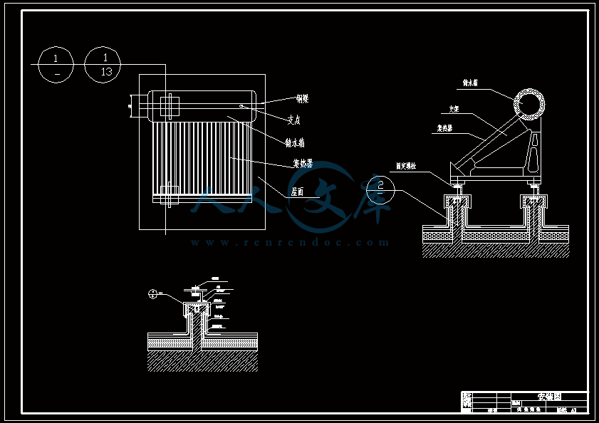
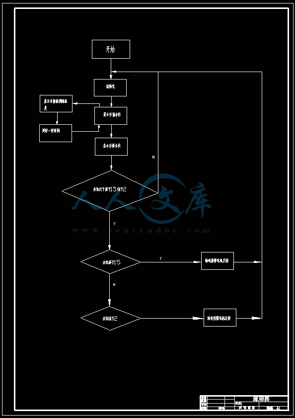
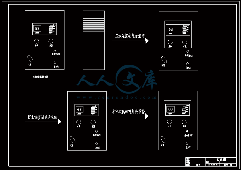
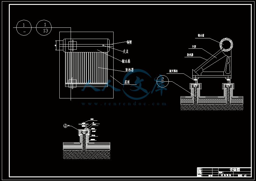
【温馨提示】压缩包内含CAD图有下方大图片预览,下拉即可直观呈现眼前查看、尽收眼底纵观。打包内容里dwg后缀的文件为CAD图,可编辑,无水印,高清图,压缩包内文档可直接点开预览,需要原稿请自助充值下载,所见才能所得,请见压缩包内的文件及下方预览,请细心查看有疑问可以咨询QQ:11970985或197216396

- 内容简介:
-
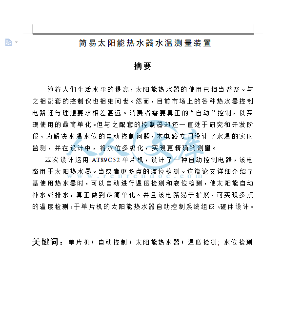
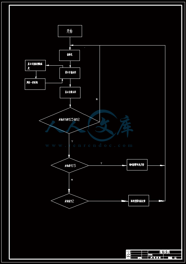
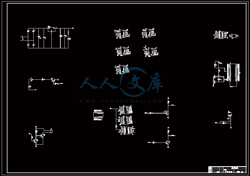
压缩包内含有CAD图纸和说明书,咨询Q 197216396 或 11970985 简易太阳能热水器水温测量装置摘要 随着人们生活水平的提高,太阳能热水器的使用已相当普及。与之相配套的控制仪也相继问世。然而,目前市场上的各种热水器控制电路还与理想要求相差甚远。消费者需要真正的“自动”控制,以实现使用的最简单化。但与之配套的控制器却还一直处于研究和开发阶段,为解决水温水位的自动控制问题,本电路专门设计了水温的实时监测,并在设计中,将水位多级化,实现更精确的测量。本次设计运用AT89C52单片机,设计了一种自动控制电路,该电路用于太阳热水器。当或者更多点的液位检测。这篇论文详细介绍了基使用热水器时,可以自动进行温度检测和液位检测,使太阳能自动补水或排水,真正做到最简单化。并且该电路易于扩展,可实现多点的温度检测,于单片机的太阳能热水器自动控制系统组成、硬件设计。关键词:单片机;自动控制;太阳能热水器;温度检测; 水位检测Solar water heater control circuit designABSTRACT With the improvement of living standard, the use of all water heaters have been very popular. Matched with the control device is also one after another. However, the current market a variety of water heater control circuit is also far from the ideal requirement. Consumers need to really automatic control, in order to achieve the most simplistic use. but are still accompanying controller has been in research and development phase, To solve the temperature and water level control problems, this circuit specifically designed for real-time monitoring of water temperature, and in the design, Multi-level of the water level to achieve more accurate measurements. Wood plays designed using AT89C52 microcontroller, the design of a control circuit, the circuit for the solar water heater. When using the heater, it will automatically detect the temperature and liquid level detection, the solar auto-replenishment, or drainage, truly the most simplistic. And easy to extend this circuit can achieve multi-point temperature measurement, level detection or more points. This paper introduces the microcontroller-based automatic control system for solar water heater composed ofhardware design. Keywords: microcontroller; control; solar water heater; temperature detection ; level detection目 录前 言1第一章 系统设计31.1设计原理31.2方案论证3第二章硬件电路设计52.1基本原理框图52.1.1太阳能热水器控制装置主要组成52.1.2太阳能热水器控制装置的工作原理52.2各部分电路原理62.2.1最小系统62.2.2显示电路92.2.3按键电路112.2.4蜂鸣器电路112.2.6液位检测电路132.2.7温度检测电路152.2.8电源电路16第三章软件设计183.1 软件分析183.2 I/O口分配18第四章 实现功能204.1 液位检测204.2温度检测204.3可扩展功能20结 论21谢辞22参考文献23附录一程序24外文资料翻译3749前 言l.太阳能热水器的发展概况及市场竞争分析 在全球能源形势紧张、气候变暖严重威胁经济发展和人们生活健康的今天,世界各国都在寻求新的能源替代战略,以求的可持续发展和在日后的发展中获取优势地位。太阳能以其清洁、源源不断、安全等显著优势,成为关注重点。在太阳能产业的发展中,太阳能热水器的热利用转换技术无疑是最为成熟的,其产业化进程也较光伏电池、太阳能发电等产业领先一步。 太阳能热水器己成为我国第一个实现商业化的可再生能源产业。自1998年起,中国就成为太阳能热水器第一大制造和消费的市场,现已经发展成为一个重耍的产业。目前,太阳能热水器与电、燃气热水器三分热水器市场,是可再生能源产业领域的第一个商业化的产品。2007年,我国太阳能热水器年产量达2340万平方米,比2006年同期增长 30%;总保有量达10800万平方米,比2006年同期增长20%。市场销售额约为320亿元人民币。 但是与之相配套的太阳能热水器控制系统却一直处在研究与开发阶段。市而上绝大多数的控制器结构简单,功能单一,智能化程度低下,用户界面不人性化,只具有温度显示功能,不具有液位显示功能。并且当水位加到一定的程度的时候也没有什么措施,只能通过手动的方法来控制水位的高度。因此根据以上要求为核心,开发出一种太阳能热水器智能控制系统,解决了目前市而上太阳能热水器控制系统存在的问题。2太阳能热水器的应用及意义 太阳能热水器应用较好的同家有西班牙、以色列、意大利、希腊、德同、荷兰、澳大利亚、日本、美过等国家。一些国家利用太阳能热水器除了提供家庭热水外,还用于采暖、空调及泳池加热等领域,其中美国的太阳能热利用主要用于泳池加热。日前太阳能热水器已在我国城乡开始推广使用,主要供应生活和洗浴热水,我国己成为界上最大的太阳能热水器生产国和应用国。太阳能热水器节能减排,实现能源替代,效果显著。经过两年多的实践,人们认识到太阳能热利用投资少、见敬效快、经济实用、节能减排,实现我国能源替代的一个好产业,国家也正大力扶持和支持,学校、宾馆、饭店、洗浴中心纷纷建设太阳能洗浴系统,太阳能热水器的市场存在扩大空间。新农村建设与建筑节能也为太阳能热水器的应用推广带来机遇。第一章 系统设计1.1设计原理太阳能热水器自动控制电路采用AT89S52单片机作为控制核心,外围加蜂鸣器控制电路、数码显示电路、水位检测电路、电机控制电路、按键电路、温度检测电路等。数码管实时切换显示当前温度与当前液位,当液位过高时,蜂鸣器报警,并且电机反转模拟排水过程;当液位过低时,蜂鸣器报警,并且电机正转模拟进水过程。本系统设计简单,成本低,性能优良,具有一定的稳定性和实用性。1.2方案论证 太阳能热水器自动控制装置有多种方案。(1)方案一 在单片机学习课程中,就遇到过一种方案,我们称其为方案一。它通过三极管的导通截止特性来判断液位的位置,并且可以通过按键切换检测压力。但是在过程中只能检测三点,虽然可以扩展,但是占了太多的I/O口,容易造成资源的浪费。而且仅显示单元就占用了12个I/O口,同样属于资源浪费。 在电机电路设计方面,方案一采用的三极管的导通截止来控制电机的正转与反转,虽然设计简单,但是过多的使用三极管以及二极管类的元器件,也会使成本升高。而且,既然是太阳能热水器的自动控制装置,那么必不可少的就是温度的检测,而方案一中却忽略了这点,造成了最大的残缺。(2)方案二 方案二主要解决了方案一中资源浪费及过于使用分立元件的缺陷。 在液位检测方面,通过利用两片CD4051芯片,它相当于一个单刀八掷开关,当INH禁止端为低电平即“0”时,开关接通哪一通道由输入的3位地址码ABC来决定。这样就简单的解决了16个点检测的问题,并且在最大程度上减少了I/O口的使用。仅使用了8个I/O口即可控制16个点的检测,如果是方案一 ,则需要使用16个I/O口。 方案一中4位数码管显示电路的断码与位码就使用了12个I/O 口,而在方案二中,使用了74LS164芯片,它是8位移位寄存器,只要给一个脉冲便传送一位数据。仅使用了2个I/O口便控制了5位数码管的显示,由于使用74LS164芯片中会遇上消隐的问题,所以在方案二中,通过硬件电路配合软件的方法很好的解决了消隐的问题,显示非常的稳定。显示出了新方案的优势。 方案二中电机驱动电路使用的是FAN8200,驱动的一个双相电机驱动电路。该电路非常简单,它几乎不需要外围元器件只要将来自于微处理器的方法控制信号从器件的输入端和触发使能端送入FAN8200便可可靠地对双相电机进行控制操作,使其正转、反转。省去了分立元件,使整个电路看起来清晰简单。 在方案二中还解决了方案一中不能检测温度缺点,使用了先进的DS18B20芯片,DS188B20数字温度传感器是Dallas公司生产的l- Wire,即单总线器件,具有线路简单、体积小的特点。因此用他组成一个测温系统,具有线路简单,在1根通信线可以挂很多这样的数字温度传感器,十分方便。(3)方案选择 通过上述两个方案的比较,便能发现方案二设计的电路比方案一的电路有极大的优势,性能全面,使用方便,而且简单、稳定。故选择方案二。第二章硬件电路设计2.1基本原理框图 2.1.1太阳能热水器控制装置主要组成 由 CPU、显示电路、按键电路、蜂鸣器电路、电机电路、液位检测电路、温度检测电路、电源电路组成,如图一CPU 蜂鸣器电路电机电路电源电路按键电路液位检测电路显示电路温度检测电路图2-1原理框图2.1.2太阳能热水器控制装置的工作原理接通电源后,显示当前水位,水位被分为16个点。并且,显示当前温度。液位显示与温度的显示切换进行。当水位显示低于或等于1时,蜂呜器报警,并且电机正转,表示进水:当水位显示高于或等于15时,蜂鸣器报警,并且电机反转,表示排水。液位检测利用CD40512.2各部分电路原理2.2.1最小系统 太阳能热水器控制电路数控部分采用AT89S52单片机作为控制核心。AT89S52是一种低功耗、高性能CMOS8位微控制器,具有8K在系统可编程Flash存储器。使用Atmel公司高密度非易失性存储器技术制造,与工业80C51产品指令和引脚完全兼容。片上Flash允许程序存储器在系统叫编程,亦适于常规编程器。在单芯片上,拥有灵巧的8位CPU和在系统可编程Flash,使得AT89S52为众多嵌入式控制应用系统提供高灵活、超有效的解决方案。AT89S52具有以下标准功能:8k字节Flash,256字节RAM,32位I/O口线,看门狗定时器,2个数据指针,三个16位定时器计数器,一个6向量2级中断结构,全双工串行口,片内晶振及时钟电路。另外,AT89S52可降至OHz静态逻辑操作,支持2种软件可选择节电模式。空闲模式下,CPU停止上作,允许RAM、定时器计数器、串口、中断继续工作。掉电保护方式下,RAM内容被保存,振荡器被冻结,单片机一。切工作停止,直到下一个中断或硬件复位为止。8位微控制器8K字节在系统可编程Flash AT89S52。 PO口: PO口是一个8位漏极开路的双向I/O 口。作为输出口,每位能驱动8个TTL逻辑电平。对PO端口写“1”时,引脚用作高阻且抗输入。当访问外部程序和数据存储器时,P0口也被作为低8位地址数据复用。在这种模式下,PO具有内部上拉电阻。在flash编程时,PO口也用来接收指令字节;存程序校验时,输出指令字节。程序校验时,需要外部上拉电阻。Pl口:Pl口是一个具有内部上拉电阻的8位双向I/O口,Pl输出缓冲器能驱动4个TTL逻辑电平。对Pl端口写“l”时,内部上拉电阻把端口拉高,此时可以作为输入口使用。作为输入使用时,被外部拉低的引脚由于内部电阻的原因,将输出电流( IIL)。此外,Pl.0和P1.2分别作定时器计数器2的外部计数输入(Pl.O/T2)和时器计数器2的触发输入( Pl.l/T2EX),具体如下表所示。在flash编程和校验时,Pl口接收低8位地址字节。 引脚号第二功能: Pl.O /T2(定时器计数器T2的外部计数输入),时钟输出; Pl.l /T2EX(定时器/计数器T2的捕捉重载触发信号和方向控制); P1.5 /MOSI(在系统编利用); P1.6 /MISO(在系统编程用): P1.7 /SCK(在系统编程用): P2口: P2口是一个具有内部上拉电阻的8位双向I/O口,P2输出缓冲器能驱动4个TTL逻辑电平。对P2端口写“1”时,内部上拉电阻把端口拉高,此时可以作为输入口使用。作为输入口使用时,被外部拉低的引脚由于内部电阻的原因,将输出电流(IIL)。 在访问外部程序存储器或用16位地址读取外部数据存储器(例如执行MOVX DPTR)时,P2口送出高八位地址。在这种应用中,P2口使用很强的内部上拉发送l。在使用8位地址(如MOVX RI)访问外部数据存储器时,P2 口输出P2锁存器的内容。 在flash编程和校验时,P2口也接收高8位地址字节和一些控制信号。 P3口:P3口是一个具有内部上拉电阻的8位双向I/O口,P2输出缓冲器能驱动4个TTL逻辑电平。对P3端口写“l,时,内部上拉电阻把端口拉高,此时可以作为输入口使用。作为输入使用时,被外部拉低的引脚由于内部电阻的原因,将输出电流( IIL)。P3口亦作为AT89S52特殊功能(第二功能如表一所示)使用,在flash编程和校验时,P3口也接收一些控制信号。表2-1端口引脚第二功能P3.0/RXD(串行输入口)P3.1/TXD(串行输出口)P3.2/INTO(外中断0)P3.3/INT1(外中断1)P3.4/TO(定时/计数器0)P3.5/T1(定时/计数器1)P3.6/WR(外部数据存储器写选通)P3.7/RD(外部数据存储器读选通) 此外,P3口还接收一些用于FLASH闪存编程和程序校验的控制信号。 RST复位输入。当振荡器工作时,RST引脚出现两个机器周期以上高电平将是单片机复位。 ALE/PROG当访问外部程序存储器或数据存储器时,ALE(地址锁存允许)输出脉冲用于锁存地址的低8位字节。一般情况下,ALE仍以时钟振荡频率的1/6输出固定的脉冲信号,因此它可对外输出时钟或用于定时目的。要注意的是:每当访问外部数据存储器时将跳过个ALE脉冲。 对FLASH存储器编程期间,该引脚还用于输入编程脉冲(PROG)。如有必要,可以通过对特殊功能寄存器(SFR)区中的8EH单元的DO位置位,可禁止ALE操作。该位置位后,只有一条MOVX和MOVC指令才能将ALE激活。此外,该引脚会被微弱拉高,单片机执行外部程序时,应设置ALE禁止位无效。 PSEN程序储存允许(PSEN)输出是外部程序存储器的读选通信号,当AT89C52由外部程序存储器取指令(或数据)时,每个机器刷期两次PSEN有效,即输出两个脉冲,在此期问,当访问外部数据存储器,将跳过两次PSEN信号。 EA/VPP外部访问允许,欲使CPU仅访问外部程序存储器(地址为OOOOH-FFFFH),EA端必须保持低电平(接地)。需注意的是:如果加密位LB1被编程,复位时内部会锁存EA端状态。如EA端为高电平(接Vcc端),CPU则执行内部程序存储器的指令。 FLASH存储器编程时,该引脚加上+12V的编程允许电源Vpp,当然这必须是该器件是使用12V编程电压Vpp。 所谓最小系统就是指由单片机和一些基木的外同电路所组成的一个可以工作的单片机系统。一般来说,它包括单片机,晶振电路和复位电路。 晶振电路:AT89S52片内有一个由高增益反相放大器构成的振荡电路。XTAL1和XTAL2分别为振荡电路的输入输出端。其振荡电路有两种组成方式:片内振荡器和片外振荡器。 复位电路:在RST输入端出现高电平时实现复位和初始化。最小系统电路 如图一所示图2-1 最小系统 2.2.2显示电路 显示部分有两种方案可供选择;一种是采用LCD液品显示,该方案具有低压微功耗、平板型结构、显示的信息量大、无电磁辐射、使用寿命长等优点,但是本设计要求显示的数据量小,不能发挥其显示内容丰富的优点,同时占用I/O口线较多。第二种方案采用LED数码管显示,该方案具有实现容易、发光亮度大、驱动电路简单等优点,其可靠性也优于LCD的显示,所以,我们通过比较,选用第二种方案数码管显示。 由6个数码管和6个74LS164组成,采用串行静态显示的方法。将数码管的8个输入端与74LS164的输出端QO-Q7相连。Pl.0和74LS164的CLK连接,作为时钟;P1.4接74LS164的A端,作为显示数据的输入端。显示电路如图二所示。图2-2 显示电路 74LS164原理:74LS164是一块14个引脚双面直插式芯片,它的工作电源比较宽,可以是3V至12V的电压;它工作的频率范围也比较宽,从05MHz都能正常工作。它是一个串行输入,并行输出的移位寄存器,并带有清除端的IC芯片,它为8位串入并出移位寄存器,1、2为串行输入端,QoQ7为并行输出端,CLK为移位时钟脉冲,上升沿移入一位;MR为清零端,低电平足并行输出为零。VCC与GND为工作电源脚;它一般正常工作电压为+5V。CLR (/MR)端:为清除端,当此引脚为低电平时,使得74LS164输出全部为0;CLK端:时钟脉冲输入端,在CP脉冲的上升沿的作用下实现移位,在CLK为0,芯片不工作;CLR为1时,74LS164保持原始状态不发生变化。 但是使用74LS164串显会出现消隐的问题。为了消除消隐,那么就必须在硬件上与软件上结合米消除消隐的问题。消隐电路如图三所示。软件上,在传数据时,先传一个高电平,直到数据传完再传送一个低电平即可。图2-3 消隐电路2.2.3按键电路 键按下后,进行温度及液位检测的切换,也可不使用。按键电路如图四所示。 图2-4 按键电路2.2.4蜂鸣器电路 以Q51的基极作为蜂鸣器控制信号的输入端与单片机I/O口相连,主要有蜂鸣器、9013与9014两个三极管及5.1K偏置电阻组成。当输入端为高电平时,Q51导通,Q52截止,蜂鸣器回路开路,蜂呜器不响;当输入端为低电平时,Q51截止,Q52导通,蜂鸣器回路闭合,蜂呜器发出响声。蜂鸣器电路如图五所示图2-5 蜂鸣电路 2.2.5电机电路 控制信号从IN端输入并经前级缓冲后送入片内控制器,然后由控制部分处理并驱动晶体管,最后由 OUT端输出方被信号以控制电机的运行。触发使能端口(CE)的作用是分别对两个通道的输出进行控制,当CE端为低电平时,无论有无输入控制信号,输出端OUT始终呈高阻抗状态。因此,要使FAN8200控制器输出工作正常,器件的触发使能端必须为高电平。当CE为高电平时,IN1为1时,电机正转;IN1为0时电机反转。电机电路如图六所示。图2-6 电机电路 2.2.6液位检测电路 液位检测控制电路,由两片CD4051与CD4066构成,但是由于考虑到成本并且所设计的电路I/O口使用并不是太多,所以,可以将CD4066省略,仅仅用两片CD4051即可实现功能。它是一种单片、COMS、8通道开关。该芯片由DTL/TTL-COMS电平转换器,带有禁止端的8选l译码器输入,分别加上控制的8个COMS模拟开关TG组成。 例如当检测到液位在端点4位置时,0、1、2、3、4点被没过,与公共端之间形成水电阻,由于水电阻阻值非常的小,所以这几点的电平被拉低。此时就可以确定在ABC点读到的数为“100”此时就可以通过单片机计算得出液位的高度。液位检测电路如图七所图2-7 液位检测电路2.2.7温度检测电路 温度检测电路有两种方案可供选择。第一种是采用热电阻温度传感器。热电阻是利用导体的电阻随温度变化的特性制成的测温元件。现应用较多的有铂、铜、镍等热电阻。其主要的特点为精度高、测量范围大、便于远距离测量。 铀的物理、化学性能极稳定,耐氧化能力强,易提纯,复制性好,工业性好,电阻率较高,因此,铂电阻用于工业检测中高精密测温和温度标准。缺点是价格贵温度系数小,受到磁场影响大,在还原介质中易被玷污变脆。按IEC标准测温范围-200650,百度电阻比W (100) =1.3850时,RO为100和10,其允许的测量误差A级为(0.15+0.002),B级为(0.3+0.005)。 铜电阻的温度系数比铂电阻大,价格低,也易于捉纯和加工;但其电阻率小,在腐蚀性介质中使用稳定性差。在工业中用-5080测温。 第二种是采用DS18B20数字温度传感器。它是DALLAS公司牛产的单总线式数字温度传感器,它具有微型化、低功耗、高性能、抗干扰能力强、易配处理器等优点,特别适用于构成多点温度测控系统,可直接将温度转化成串行数字信号(提供9位二进制数字)给单片机处理,且在同一总线上可以挂接多个传感器芯片。它具有3引脚T0-92小体积封装形式,温度测量范围为-55+125,可编程为9位-12位A/D转换精度,测温分辨率可达0.0625,被测温度用符号扩展的16位数字量方式串行输出,其工作电源既可在远端引入,也可采用寄生电源方式产生,多个DS18B20可以并联到3根或2根线上,CPU只需一根端口线就能与多个DS18B20通信,占用微处理器的端口较少,可节省大量的引线和逻辑电路。以上|特点使DS18B20非常适用于远距离多点温度检测系统。 根据设计要求,选择第二种方案。DS18B20硬件电路的链接非常简单,仅一根电源线,一根地线和一根数据线即可。温度检测电路如图八所示。图2-8 温度检测电路2.2.8电源电路 由于电源电压为5V,所以电路中省去了稳压电源部分的电路,直接使用电源电压即可。在电源与地之间加滤波电容,稳定输入到芯片上的电源电压。电源电路如图九所示。图2-9 电源电路第三章软件设计3.1 软件分析太阳能热水器控制电路设计的软件部分由主程序、检测温度子裎序、压缩16进制数变成压缩10进制数子程序、压缩10进制数变成非压缩十进制数子程序、代码变段码码子程序、显示子程序、液位检测子程序以及延时子程序组成。在平时编程中,用C语言编写程序有利于实现较复杂的算法,但是汇编语言程序则具有较高的效率且容易精细计算程序运行的时间。不论是什么语言,始终是要被电脑转换成C语言进行执行的。所以,在此次设计中,编程采用的是汇编语。3.2 I/O口分配表3-1I/O口P3.0P3.1P3.3P1.5P1.1分配74LS164数据端74LS164时钟电机转向控制端蜂鸣器控制端4051-AI/O口P1.2P1.3P1.4P1.6P1.7分配4051-B4051-C4051-INHK1K23.3软件流程图开始初始化显示当前水位显示当前水位延时一段时间显示当前检测的温度水位处于高于15低于2水位高于15点水位低于2点蜂鸣器报警 电机反转蜂鸣器报警 电机正转YNYYN第四章 实现功能4.1 液位检测将水尺放进水中,通电之后,显示当前的水位。最低点水位为1,最高点水位为16。当水位低于点2时,显示H02的同时峰呜器响,电机正转,模拟进水过程;直到水位高于点2后,蜂呜器停止发声,电机不转。当高于水位点l5时,显示H 15的同时蜂鸣器响,电机反转,模拟排水过程;直到水位低于点15后,蜂呜器停止发生,电机不转。4.2温度检测实时监测当前温度,与水位切换显示。例如显示为C 27.6。4.3可扩展功能 液位可以扩展为更多点的测量,以保证测量的准确。温度亦可,只需要多加几个I/O,边可以检测多点的温度,使用非常简单。结 论 水,是一切生命的源泉,是地球万物生存的基础,它使地球万物欣欣向容但是,地球上的水资源正在不断减少,据调查:占世界人口40%的80个国家正面临着水危机,发展中国家约有10亿人喝不到清洁的水,17亿的人没有良好的卫生设施每年约有2500万人死于饮用不清洁水我国的水资源也相当短缺,人均水资源拥有量是世界人均水资源拥有量的1/5,许多城市己严重缺水华北地区由于过度引用地下水,己造成严重的地面下沉现象水资源短缺己成为当今世界要而临的重人问题。 如果一广人家溢出一些水,那么千家万广溢出的水加起来,浪费的水就不是一个小数目了,所以考虑设计一个自动补水排水的装置,来节约用水。本设计成本低,易使用。 在设计过程中,将所学的专业理论知识与实际开发实际结合起来,理论联系实际,提高了专业技能。人量查阅资料,对专业知识有了更深入的理解和认识,扩展了知识面,从课题立项、方案论证、理论设计、线路图绘制、制版设计到电路焊接与训试,全而了解和掌握了课题开发的基础方法和步骤,使用了单片机原理、模拟电子技术、数字电路技术、Protel 99se制图技术等专业技能。并在原有的计算机理论于操作的基础上,巩固了对办公软件的应用,为以后的实际工作打下了良好的基础。 本产品有以下特点:可靠性高、成本较低、制作简单、体积小、重量轻、消耗小、易于系统设计、操作方便,只要上电,便可自动控制,实用性强,不容易损坏;适应性广,不但适用太阳能热水器,可以应用于各种需要控利制抽水的地方,如自来水储水箱。但是由于其功能还是有所局限,所以仍有需要改进的地方。谢 辞 在设计期间,梁老师为我提供了论文的种种要求以及答辩时所遇到的各种问题。梁老师一丝不苟的作风,严谨求实的态度使我深受感动,没有这样的帮助和关怀和熏陶,我不会这么顺利的完成毕业设计。在此向梁老师表示深深的感谢和崇高的敬意! 在临近毕业之际,我还要借此机会向在这四年中给予我诸多教诲和帮助的各位老师表示由衷的谢意,感谢他们四年来的辛勤栽培。不积跬步何以至千里,各位任课老师认真负责,在他们的悉心帮助和支持下,我能够很好的掌握和运用专业知识,并在设计中得以体现,顺利完成毕业设计。同时,在设计过程中,我还参考了有关的书籍,在这里一并向有关的作者表示谢意。我最后还要感谢同组的各位同学以及我的各位室友,在毕业设计的这段时间里,你们给了我很多的启发,提出了很多宝贵的意见,对于你们帮助和支持,在此我表示深深地感谢! 参考文献1刘松单片机原理与接口技术,天津电子信息职业技术学院,20092李忠国、陈刚。单片机心用技能实训人民邮电出版社,20063曹金玲。单片机原理与接口技术课程设计指导书天律电子信息职业技术学院,20084王毅单片机器件应用手册人民邮电出版社,19945胡汗才,单片机原理及接口技术,清华大学出版社19966邵敏权,刘权单片机原理实验及应用吉林科学技术出版社,1995_17刘笃仁、韩保君传感器原理及应用技术机械工业出版社,2003.88童诗白.模拟电子技术基础。高等教育出版社,20019周航慈,单片机应用程序设计,北京航空航天大学出版社, 1991.810赖麒文, 8051单片机C语言彻底应用科学出版社,200211常通义。微型计算机原理及接口技术华中科技大学出版社,200312胡乾斌.单片微型计算机原理与应用M. 武汉:华中科技大学出版社,1997.13沙占友,王彦朋,孟志永.单片机外围电路设计M. 北京:电子工业出版社, 2003:135-137,222-226.14刘焕平,童一帆.单片机原理及应用M. 北京:北京邮电大学出版社。200815李朝青,单片机原理及接口技术(第3版)M . 北京:北京航空航天出版社。200616金伟正.单线数字温度传感器的原理与应用J. 电子技术应用,2000,17沙占友. 由DS182O组成的单线数字温度计原理与应用J. 电测与仪表,199918周云波. 由 DS18B20单线数字温度计构成的单线多点温度测量系统J. 电子技术应用,1996(2):15-20.19王仲生,智能检测与控制技术M. 西安:西北工业大学出版社,2002.20路松行. 电工与电子技术M. 西安:西安电子科技大学出版社。2006附录一程序:标志:32H水位标志:BAOZHI BIT 33H;显示标志;33H=O显水位,33H=1显湍度:DINGS BIT 34H;34H=O定时,34H=1计数;alarmflag BIT 24H;蜂鸣器报警标志:74164A BIT P3.0;164数据端:CLK BIT P3.1;164时钟:CE BIT Pl.5;电机控制端为l:Ml BIT P3.3;P3.3=1电机正转,反之反转。:SPK BIT P3.5;蜂呜器控制:LA BIT Pl.1;4051点 A:LB BIT Pl.2;4051点B:LC BIT Pl.3;4051点C:40511NH BIT Pl,4;4051的INH端:Kl BIT Pl.6;按键l(水位检测状态):K2 BIT Pl.7;按键2(温度检测状态) ORG OOOOH LJMP MAIN ORG 0100HMAIN: MOV SP,#60H CLR Pl.5;电机不转MM3: MOV 50Hj#20H;水位显示时长MM33: LCALL SWEI:水位检测 DJNZ 50H,MM33 LCALL XIANC;显C SJMP MM1MMl: MOV 50H,#10H;湍度显示时长MM2: LCALL WDCJ;温度检测 DJNZ 50H,MM2 LCALL XIANH;显H SJMP MAINWDCJ: LCALL GET_TEMP;采集温度值以16进制数,低位放R7,高位放R6CHENGFA: MOV R3,#0AH;0AH乘以温度值R7R6,结果在R2R3R4R5中,R2最高字节 MOV R2,#00H LCALL MULDCHUFA: MOV R6,#00H;被除数在R2R3R4R5中,R2最高字节,除数在R6R7, R6高字节,结果在R2R3。 MOV R7,#10H MOV R2,#00H MOV R3,#00H LCALL DIVD MOV 20H,R3;R3低字节 MOV 21H,R2 ACALL YASO;压缩16进制数变成压缩10进制数 ACALL Lll;压缩一非压缩 ACALL DAIM;代码一一段码 ACALL XIAN; 显示 LCALL XIANC LCALL XIAOSH LCALL DEL2 RETGET TEMP:CLR PSW4 CLR PSW3;设置工作寄存器当前所在的区域 CLR EA;使用DS1820一定要禁止任何中断产生 LCALL INT:调用初始化子程序 MOV A#0C,CH LCALL WRITE :送入跳过ROM命令 MOV A,#44H LCALL WRITE:送入湍度转换命令 LCALL INT:温度转换完全,再次初始化DS1820 MOV A,#0CCH LCALL WRITE:送入跳过ROM命令 MOV A,#OBEH LCALL WRITE:送入读温度暂存器命令 LCALL READ MOV R7,A :读出温度值低字节存入R7 LCALL READ SETB EA RETINT: CLR EA :初始化DS1820LO: CLR P3.4 :DS1820总线为低复位电平 MOV R2,#200L1: CLR P3.4 DJNZ R2,LI ;总线复位电平保持400US SETB P3.4 :释放DS1820总线 MOV R2,#200L4: DJNZ R2,L4 :释放DSI820总线保持60US CLR C;清存在信号 ORL C,P3.4 JC LO;存在吗?不存在则重新来。 MOV R6,#80HL5: ORL C,P3.4 JC L3DJNZ R6,L5 SJMP L0L.3: MOV R2,#240L.2: DJNZ R2,L2 RETWRITE:CLR EA MOV R3,#8WRl: SETB P3.4 MOV R4,#8 RRC, A CLR P3.4WR2: DJNZ R4,WR2 MOV P3.4 ,C MOV R4,#20WR3: DJNZ R4,WR3 DIFNZ R3,WRl SETB P3.4 RETREAD: CLR EA MOV R6,#8;连续读8个BIT REl: CL.R P3.4;改前总线保持为低 MOV R4,#4 NOP SETB P3.4;开始读,总线释放RE2: DJNZ R4,RE2;持续8US MOV C,P3.4;从DS1820总线读得一个BIT RRC, A; MOV R5j#30RE3: DJNZ R5,RE3;持续60US DJNZ R6,REI;读下一个BIT SETB P3.4;重新释放DS1820总线 RETYASO: MOV RO, #20H;压缩16迸制数变成压缩10进制数 MOV R7, #02H MOV Rl, #28H LC,ALLLY1 RETLYl: MOV A, RO MOV R5,A MOV A, Rl MOV R6,A MOV A, R7 INC A MOV R3,A CLR ALY2.: MOV Rlj A INC, Rl DINZ R3, LY2 MOV A, R7 MOV B, #08H MUL AB MOV R3, ALY3: MOV A,R5 MOV RO, A MOV A, R7 MOV R2, A CLR CLY5: MOV A,R0 RLC A MOV R0, A INC R0 DJNZ R2, LY5 MOV A, R6 MOV Rl, A MOV A, R7 MOV R2, A INC R2LY4: MOV A, Rl ADDC A, RI DA A MOV Rl,A INC Rl DJNZ R2, LY4 D.JNZ R3, LY3 RETL11: MOV Rl,#10H;li缩10进制数变成非压缩十进制数 MOV R2,#03H MOV R0,#28HL12: MOV A, R0 ANL A, #0FH MOV R1jA INC Rl MOV A, Ca)R0 SWAP A ANL A, #0FH MOV RljA INC R0 INC Rl DJNZ R2, L12 RETDAIM: MOV R2,#05H;代码变段码码 MOV R0, #10H MOV Rl, #20HL12F: MOV A,R0 ADD A, #06H MOVC, A, A+PC, MOV Rl, A INC R0 INC Rl DJNZ R2, L12F RET DB 3FH,06H,5BH,4FH,66H,6DH,7DH,07H DB 7FH,6FH,77H,7CH,39H,5EH,79H,71H DB 00H,40H,73H,03H,18H,23H,1CH,3DH,76H,0FH,1EH,38HXIAN: CLR P3.2 MOV R0, #20H;显示 MOV R2,#05HLPl: MOV Rl,#08H MOV A,ROLP2: RLC A MOV P3.O,C CLR P3.1 SETB P3.1 DJNZ Rl,LP2 INC RO DJNZ R2,LPI SETB P3.2 RETDEL: MOV R5,#14HY3: MOV R6,#0FFHY2: MOV R7,#h0FFHYl: DJNZ R7,Y1 DJNZ R6, Y2 DJNZ R5,Y3 RETXIAOSH: MOV A,21H;小数点程序 ORL A, #S0H MOV 21H,A LCALL XIAN RETLBB: MOV A,#10H;清显示 MOV R0, #10H MOV R2,#05HLBl: MOV R0,A INC. R0 DJNZ R2, LB1 RETBEING: MOV 10H,#10H MOV 11H,#10H MOV 12H,#10H MOV 13H,#10H MOV 14H,#18H ACALL DAIM;代码一段码 ACALL XIAN; 显示 RETXIANC :;MOV 10H,#10H ;MOV 11H,#10H ;MOV 12H:#10H MOV I3H7#10H MOV 14H,#0CH ACALL DAIM;代码一段码 ACALL XIAN; 显示; RETMULD: MOV A,R3;双字节乘法子程 MOV B,R7 MUL AB MOV R4,B MOV R5,A MOV A,R3 MOV B,R6 MUL AB ADD A,R4 MOV R4,A CLR A ADDC A,B MOV R3,A MOV A,R2 MOV B,R7 MUL AB ADD A,R4 MOV R4,A MOV A,R3 ADDC A,B MOV R3,ACLR ARLC AXCH A,R2 MOV B,R6 MUL AB ADD A,R3 MOV R3,A MOV A,R2 ADDC A,B MOV R2,A RETDIVD: CLR C;双字节除法子群 MOV A,R3 SUBB A,R7 MOV A,R2 SUBB A,R6 JC DVD1 SETB OV RETDVDl: MOV B,#10HDVD2: CLR C MOV A,.R5 RLC A MOV R5,A MOV A,R4RLC A MOV R4,AMOV A,R3RLC AMOV R3,AXCH A,R2RLC AXCH A,R2MOV F0,C CLR CSUBB A,R7MOV Rl,AMOV A,R2SUBB A,R6ANL C,/F0JC DVD3MOV R2,AMOV A,RlMOV R3,AINC R5DVD3: DJNZ B,DVD2 MOV A,R4 MOV R2,A MOV A,.R5 MOV R3,A CLR OV RETSWEI: MOV 32H,#10H;把1 6送32HSW1: MOV A,32H;A=16 DEC A;减 l RL A;乘以2 ADD A,#0E1H;保护没有用的位 MOV Pl,A;输出扫描值 NOP NOP NOP NOP NOP NOP JNB Pl.0,SWll;为0该点在水中应显示,否则点位减1 MOV A,32H CLR C SUBB A,#01H JC SW11 MOV 32H,A SJMP SW1 LCALL DEL RETSW11: LCALL. DEL2 MOV 20H,32H; MOV 21H,#00H ACALL YASO;压缩16进制数变成压缩 10进制数 ACALL 111;压缩-非压缩 LCALL DAIM LCALL XIAN LCALL XIANHBJ: CLR Pl.5 SETB P3.5 MOV A,32H CLR C SUBB A,#OIH JC SWL MOV A,3 2.H CLR C SUBB A,#OFH JNC SWH RETSWL: CLR P3.5;水位低报警 SETB Pl.5;电机正转 SETB P3.3 LCALL DEL SETB P3.5 CLR Pl.5 RETSWH: CLR P3.5;水位低报警 SETB Pl.5;电机反转 CLR P3.3 LCAL LDEL SETB P3.5 CLR Pl.5 RETXIANH: MOV 12H,#10H MOV 13H,#10H MOV 14H,#18H ACALL DAIM;代码一段码 ACALL XIAN; 显示 RETDEL2: MOV R5,#80HY33: MOV R7, #OFFHYll: DJNZ R7, Yll DJNZ R5,Y33 RET END外文资料翻译英文资料FEATURES_ Unique 1-Wire interface requires only oneport pin for communication_ Multidrop capability simplifies distributedtemperature sensing applications_ Requires no external components_ Can be powered from data line. Power supplyrange is 3.0V to 5.5V_ Zero standby power required_ Measures temperatures from -55C to+125C. Fahrenheit equivalent is -67F to+257F_ 0.5C accuracy from -10C to +85C_ Thermometer resolution is programmablefrom 9 to 12 bits_ Converts 12-bit temperature to digital word in750 ms (max.)_ User-definable, nonvolatile temperature alarmsettings_ Alarm search command identifies andaddresses devices whose temperature isoutside of programmed limits (temperaturealarm condition)_ Applications include thermostatic controls,industrial systems, consumer products,thermometers, or any thermally sensitivesystemDESCRIPTIONThe DS18B20 Digital Thermometer provides 9 to 12-bit (configurable) temperature readings whichindicate the temperature of the device。Information is sent to/from the DS18B20 over a 1-Wire interface, so that only one wire (and ground)needs to be connected from a central microprocessor to a DS18B20. Power for reading, writing, andperforming temperature conversions can be derived from the data line itself with no need for an external power source.Because each DS18B20 contains a unique silicon serial number, multiple DS18B20s can exist on the same 1-Wire bus. This allows for placing temperature sensors in many different places. Applications where this feature is useful include HVAC environmental controls, sensing temperatures inside buildings, equipment or machinery, and process monitoring and control.OVERVIEWThe block diagram of Figure 1 shows the major components of the DS18B20. The DS18B20 has four main data components: 1) 64-bit lasered ROM, 2) temperature sensor, 3) nonvolatile temperature alarmtriggers TH and TL, and 4) a configuration register. The device derives its power from the 1-Wire communication line by storing energy on an internal capacitor during periods of time when the signal line is high and continues to operate off this power source during the low times of the 1-Wire line until it returns high to replenish the parasite (capacitor) supply. As an alternative, the DS18B20 may also be powered from an external 3 volt - 5.5 volt supply.Communication to the DS18B20 is via a 1-Wire port. With the 1-Wire port, the memory and control functions will not be available before the ROM function protocol has been established. The master must first provide one of five ROM function commands: 1) Read ROM, 2) Match ROM, 3) Search ROM, 4)Skip ROM, or 5) Alarm Search. These commands operate on the 64-bit lasered ROM portion of eachdevice and can single out a specific device if many are present on the 1-Wire line as well as indicate to the bus master how many and what types of devices are present. After a ROM function sequence has been successfully executed, the memory and control functions are accessible and the master may then provide any one of the six memory and control function commands.One control function command instructs the DS18B20 to perform a temperature measurement. The result of this measurement will be placed in the DS18B20s scratch-pad memory, and may be read by issuing a memory function command which reads the contents of the scratchpad memory. The temperature alarm triggers TH and TL consist of 1 byte EEPROM each. If the alarm search command is not applied to the DS18B20, these registers may be used as general purpose user memory. The scratchpad also contains a configuration byte to set the desired resolution of the temperature to digital conversion. Writing TH, TL,and the configuration byte is done using a memory function command. Read access to these registers is through the scratchpad. All data is read and written least significant bit first.PARASITE POWERThe block diagram (Figure 1) shows the parasite-powered circuitry. This circuitry “steals” power whenever the DQ or VDD pins are high. DQ will provide sufficient power as long as the specified timing and voltage requirements are met (see the section titled “1-Wire Bus System”). The advantages of parasite power are twofold: 1) by parasiting off this pin, no local power source is needed for remote sensing of temperature, and 2) the ROM may be read in absence of normal power.In order for the DS18B20 to be able to perform accurate temperature conversions, sufficient power mustbe provided over the DQ line when a temperature conversion is taking place. Since the operating current of the DS18B20 is up to 1.5 mA, the DQ line will not have sufficient drive due to the 5k pullup resistor.This problem is particularly acute if several DS18B20s are on the same DQ and attempting to convert simul -taneously.There are two ways to assure that the DS18B20 has sufficient supply current during its active conversion cycle. The first is to provide a strong pullup on the DQ line whenever temperature conversions or copies to the E2 memory are taking place. This may be accomplished by using a MOSFET to pull the DQ line directly to the power supply as shown in Figure 2. The DQ line must be switched over to the strong pullupwithin 10 s maximum after issuing any protocol that involves copying to the E2 memory or initiates temperature conversions. When using the parasite power mode, the VDD pin must be tied to ground.Another method of supplying current to the DS18B20 is through the use of an external power supply tied to the VDD pin, as shown in Figure 3. The advantage to this is that the strong pullup is not required on the DQ line, and the bus master need not be tied up holding that line high during temperature conversions.This allows other data traffic on the 1-Wire bus during the conversion time. In addition, any number ofDS18B20s may be placed on the 1-Wire bus, and if they all use external power, they may allsimultaneously perform temperature conversions by issuing the Skip ROM command and then issuing the Convert T command. Note that as long as the external power supply is active, the GND pin may not be floating.The use of parasite power is not recommended above 100C, since it may not be able to sustain communications given the higher leakage currents the DS18B20 exhibits at these temperatures. For applications in which such temperatures are likely, it is strongly recommended that VDD be applied to the DS18B20.For situations where the bus master does not know whether the DS18B20s on the bus are parasite powered or supplied with external VDD, a provision is made in the DS18B20 to signal the power supply scheme used. The bus master can determine if any DS18B20s are on the bus which require the strong pullup by sending a Skip ROM protocol, then issuing the read power supply command. After this command is issued, the master then issues read time slots. The DS18B20 will send back “0” on the1-Wire bus if it is parasite powered; it will send back a “1” if it is powered from the VDD pin. If the master receives a “0,” it knows that it must supply the strong pullup on the DQ line during temperature conversions. See “Memory Command Functions” section for more detail on this command protocol.OPERATION - MEASURING TEMPERATUREThe core functionality of the DS18B20 is its direct-to-digital temperature sensor. The resolution of the DS18B20 is configurable (9, 10, 11, or 12 bits), with 12-bit readings the factory default state. This equates to a temperature resolution of 0.5C, 0.25C, 0.125C, or 0.0625C. Following the issuance of the Convert T 44h command, a temperature conversion is performed and the thermal data is stored in the scratchpad memory in a 16-bit, sign-extended twos complement format. The temperatureinformation can be retrieved over the 1-Wire interface by issuing a Read Scratchpad BEh commandonce the conversion has been performed. The data is transferred over the 1-Wire bus, LSB first. The MSB of the temperature register contains the “sign” (S) bit, denoting whether the temperature is positive or negative.Table 2 describes the exact relationship of output data to measured temperature. The table assumes 12-bit resolution. If the DS18B20 is configured for a lower resolution, insignificant bits will contain zeros. For Fahrenheit usage, a lookup table or conversion routine must be used.OPERATION - ALARM SIGNALINGAfter the DS18B20 has performed a temperature conversion, the temperature value is compared to the trigger values stored in TH and TL. Since these registers are 8-bit only, bits 9-12 are ignored for comparison. The most significant bit of TH or TL directly corresponds to the sign bit of the 16-bit temperature register. If the result of a temperature measurement is higher than TH or lower than TL, an alarm flag inside the device is set. This flag is updated with every temperature measurement. As long asthe alarm flag is set, the DS18B20 will respond to the alarm search command. This allows many DS18B20s to be connected in parallel doing simultaneous temperature measurements. If somewhere the temperature exceeds the limits, the alarming device(s) can be identified and read immediately without having to read non-alarming devices.64-BIT LASERED ROMEach DS18B20 contains a unique ROM code that is 64-bits long. The first 8 bits are a 1-Wire family code (DS18B20 code is 28h). The next 48 bits are a unique serial number. The last 8 bits are a CRC of the first 56 bits. (See Figure 4.) The 64-bit ROM and ROM Function Control section allow the DS18B20 to operate as a 1-Wire device and follow the 1-Wire protocol detailed in the section “1-Wire Bus System.” The functions required to control sections of the DS18B20 are not accessible until the ROM function protocol has been satisfied. This protocol is described in the ROM function protocol flowchart (Figure 5). The 1-Wire bus master must first provide one of five ROM function commands: 1) Read ROM, 2) Match ROM, 3) Search ROM, 4) Skip ROM, or 5) Alarm Search. After a ROM function sequence has been successfully executed, the functions specific to the DS18B20 are accessible and thebus master may then provide one of the six memory and control function commands.CRC GENERATIONThe DS18B20 has an 8-bit CRC stored in the most significant byte of the 64-bit ROM. The bus mastercan compute a CRC value from the first 56-bits of the 64-bit ROM and compare it to the value stored within the DS18B20 to determine if the ROM data has been received error-free by the bus master. The equivalent polynomial function of this CRC is:CRC = X8 + X5 + X4 + 1The DS18B20 also generates an 8-bit CRC value using the same polynomial function shown above and provides this value to the bus master to validate the transfer of data bytes. In each case where a CRC is used for data transfer validation, the bus master must calculate a CRC value using the polynomial function given above and compare the calculated value to either the 8-bit CRC value stored in the 64-bit ROM portion of the DS18B20 (for ROM reads) or the 8-bit CRC value computed within the DS18B20(which is read as a ninth byte when the scratchpad is read). The comparison of CRC values and decision to continue with an operation are determined entirely by the bus master. There is no circuitry inside the DS18B20 that prevents a command sequence from proceeding if the CRC stored in or calculated by the DS18B20 does not match the value generated by the bus master.The 1-Wire CRC can be generated using a polynomial generator consisting of a shift register and XOR gates as shown in Figure 6. Additional information about the Dallas 1-Wire Cyclic Redundancy Check is available in Application Note 27 entitled “Understanding and Using Cyclic Redundancy Checks with Dallas Semiconductor Touch Memory Products.” The shift register bits are initialized to 0. Then starting with the least significant bit of the family code,1 bit at a time is shifted in. After the 8th bit of the family code has been entered, then the serial number is entered. After the 48th bit of the serial number has been entered, the shift register contains the CRC value. Shifting in the 8 bits of CRC should return the shift register to all 0s.MEMORYThe DS18B20s memory is organized as shown in Figure 8. The memory consists of a scratchpad RAM and a nonvolatile, electrically erasable (E2) RAM, which stores the high and low temperature triggers TH and TL, and the configuration register. The scratchpad helps insure data integrity when communicating over the 1-Wire bus. Data is first written to the scratchpad using the Write Scratchpad 4Eh command. It can then be verified by using the Read Scratchpad BEh command. After the data has been verified, a Copy Scratchpad 48h command will transfer the data to the nonvolatile (E2) RAM. This process insures data integrity when modifying memory. The DS18B20 EEPROM is rated for a minimum of 50,000 writes and 10 years data retention at T = +55C.The scratchpad is organized as eight bytes of memory. The first 2 bytes contain the LSB and the MSB of the measured temperature information, respectively. The third and fourth bytes are volatile copies of TH and TL and are refreshed with every power-on reset. The fifth byte is a volatile copy of the configuration register and is refreshed with every power-on reset. The configuration register will be explained in more detail later in this section of the datasheet. The sixth, seventh, and eighth bytes are used for internal computations, and thus will not read out any predictable pattern.It is imperative that one writes TH, TL, and config in succession; i.e. a write is not valid if one writesonly to TH and TL, for example, and then issues a reset. If any of these bytes must be written, all three must be written before a reset is issued.There is a ninth byte which may be read with a Read Scratchpad BEh command. This byte contains a cyclic redundancy check (CRC) byte which is the CRC over all of the eight previous bytes. This CRC is implemented in the fashion described in the section titled “CRC Generation”.1-WIRE BUS SYSTEMThe 1-Wire bus is a system which has a single bus master and one or more slaves. The DS18B20 behaves as a slave. The discussion of this bus system is broken down into three topics: hardware configuration, transaction sequence, and 1-Wire signaling (signal types and timing).ABSOLUTE MAXIMUM RATINGS*Voltage on Any Pin Relative to Ground -0.5V to +6.0VOperating Temperature -55C to +125CStorage Temperature -55C to +125CSoldering Temperature See J-STD-020A specification* This is a stress rating only and functional operation of the device at these or any other conditions above those indicated in the operation sections of this specification is not implied. Exposure to absolute maximum rating conditions for extended periods of time may affect reliability.NOTES:1. All voltages are referenced to ground.2. Logic one voltages are specified at a source current of 1 mA.3. Logic zero voltages are specified at a sink current of 4 mA.4. Active current refers to either temperature conversion or writing to the E2 memory. Writing to E2 memory consumes approximately 200 A for up to 10 ms.5. Input load is to ground.6. Standby current specified up to 70C. Standby current typically is 3 A at 125C.7. To always guarantee a presence pulse under low voltage parasite power conditions, VILMAX may have to be reduced to as much as 0.5V.中文翻译1.1 一般说明 DS1820数字温度计提供9位温度读数,指示器件的温度。 信息经过单线接口送入DS1820或从DS1820送出,因此从中央处理器器到DS1820仅需连接一条线(和地)。读,写和完成温度变换所需的电源可以由数据线本身提供,而不需要外部电源。 因为每一个DS1820有唯一的系列号(silicon serial number),因此多个DS1820可以存在于同一条单线总线上。这允许在许多不同的地方放置温度灵敏器件。此特性的应用范围包括HVAC环境控制,建筑物、设备或机械内的温度检测,以及过程监视和控制中的温度检测。1.2特性独特的单线接口,只需1一个接口引脚即可通信多点( multidrop)能力使分布式温度检测应用得以简化不需要外部元件可用数据线供电不需各份电源测量范围从-55至+125,增量值为0.5。等效的华氏温度范围是-67。F至257。F,增量值为0.9。F以9位数字值方式读出温度在1秒(典型值)内把温度变换为数字用户可定义的,非易失性的温度告警设置告警搜索命令识别和寻址温度在编定的极限之外的器件(温度告警情况)应用范围包括恒温控制,工业系统,消费类产品,温度计或任何热敏系统2.1综述DS1820有三令丰要的数据部件:1)64位激光(lasered) ROM;2)温度灵敏元件;3)非易失性温度告警触发器TH和TL。器件从单线的通信线取得其电源,在信号线为高电平的时间周期内,把能量贮存在内部的电容器中,在单信号线为低电平的时间期内断开此电源,直到信号线变为高电平重新接上寄生
- 温馨提示:
1: 本站所有资源如无特殊说明,都需要本地电脑安装OFFICE2007和PDF阅读器。图纸软件为CAD,CAXA,PROE,UG,SolidWorks等.压缩文件请下载最新的WinRAR软件解压。
2: 本站的文档不包含任何第三方提供的附件图纸等,如果需要附件,请联系上传者。文件的所有权益归上传用户所有。
3.本站RAR压缩包中若带图纸,网页内容里面会有图纸预览,若没有图纸预览就没有图纸。
4. 未经权益所有人同意不得将文件中的内容挪作商业或盈利用途。
5. 人人文库网仅提供信息存储空间,仅对用户上传内容的表现方式做保护处理,对用户上传分享的文档内容本身不做任何修改或编辑,并不能对任何下载内容负责。
6. 下载文件中如有侵权或不适当内容,请与我们联系,我们立即纠正。
7. 本站不保证下载资源的准确性、安全性和完整性, 同时也不承担用户因使用这些下载资源对自己和他人造成任何形式的伤害或损失。

人人文库网所有资源均是用户自行上传分享,仅供网友学习交流,未经上传用户书面授权,请勿作他用。
 川公网安备: 51019002004831号