




版权说明:本文档由用户提供并上传,收益归属内容提供方,若内容存在侵权,请进行举报或认领
文档简介
1、DSP group 2007 chap9-ed1 1 Chapter 9 IIR Digital Filter DesignSpecifications for DT filtersBilinear transform method for lowpass digital filterOther types of IIR Filters designComputer-aided Design of IIR digital filtersDSP group 2007 chap9-ed1 2 IntroductionAn important research on digital filter:
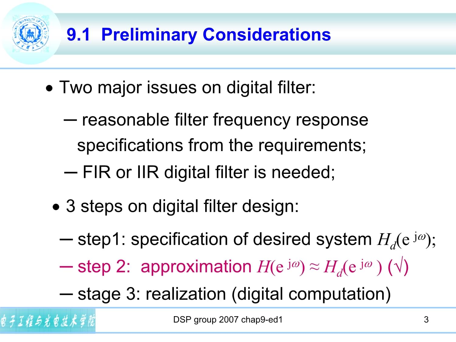
2、Determine realizable transfer function approximating the given frequency specifications; The process of deriving the transfer function is called digital filter design;Another important research on digital filter: Realization of digital filter (IIR/FIR)DSP group 2007 chap9-ed1 3 9.1 Preliminary Consi
3、derationsTwo major issues on digital filter: reasonable filter frequency response specifications from the requirements; FIR or IIR digital filter is needed;3 steps on digital filter design: step1: specification of desired system Hd(e j); step 2: approximation H(e j) Hd(e j ) () stage 3: realization
4、(digital computation)DSP group 2007 chap9-ed1 4 9.1.1 Digital filter specifications0PassbandStopband Specifications: Transition Tolerance (peak ripple value)Edge frequencySpecifications in terms of loss function: DSP group 2007 chap9-ed1 5 9.1.1 Digital filter specifications peak passband ripple min
5、imum stopband attenuationExample 9.1: p = 0.1dB, s= 35 dB.Solution: DSP group 2007 chap9-ed1 6 9.1.1 Digital filter specificationsSpecifications in normalized form: 0PassbandStopband Transition maximum passband deviation maximum stopband magnitude edge frequency usually specified in HzDSP group 2007
6、 chap9-ed1 7 9.1.1 Digital filter specificationsExample9.2 Highpass: Fp = 7kHz, Fs= 3kHz. FT = 25kHzSolution: 9.1.2 Selection of the filter type IIR digital filterP133 3.65DSP group 2007 chap9-ed1 8 9.1.2 Selection of the filter typeCausal;Stable (an important factor needs to be considered);Lowest o
7、rder FIR digital filterDSP group 2007 chap9-ed1 9 9.1.2 Selection of the filter type Advantages and properties of FIR digital filterLinear phase;Always Stable;Order NFIR NIIR; multiplications per output sample: FIR filter: NFIR+1 or half, IIR filter: 2NIIR+1; The IIR filter is usually computationall
8、y more efficient.DSP group 2007 chap9-ed1 10 9.1.3 Basic approach to IIR filter design Transform the analog filter into the desired digital filter. Reasons for IIR design method Analog filter design techniques are highly advanced; They usually yield closed-form solutionsExtensive tables are availabl
9、e for analog filter design;Many applications require the digital simulation of analog filters. DSP group 2007 chap9-ed1 11 9.1.3 Basic approach to IIR filter design Transform rules: the imaginary (j) axis in the s-plane be mapped onto the unit circle of the z-plane; A stable analog transfer function
10、 be transformed into a stable digital transfer function. DSP group 2007 chap9-ed1 12 9.1.3 Basic approach to IIR filter design Steps for this transforming: Step 1: Specifications Conversion;Step 2: analog filter design; prototype analog filterStep 3: system function transforming (From s-plane to z-p
11、lane) .DSP group 2007 chap9-ed1 13 9.1.5 Scaling the Digital Transfer Function For implementation: Ht(z)=KH(z), so that the maximum magnitude in the passband is unity. K=1/Hmax.DSP group 2007 chap9-ed1 14 9.2 Bilinear Transformation Method of IIR Filter Design9.2.1 Bilinear TransformationOne-to-one
12、mapping, it maps a single point in the s-plane to a unique point in the z-plane, and vice versa.DSP group 2007 chap9-ed1 15 9.2.1 Bilinear Transformation Mapping relationsDSP group 2007 chap9-ed1 16 9.2.1 Bilinear Transformation Mapping relationsjs - planez =e jRe zjIm zz - planeDSP group 2007 chap9
13、-ed1 17 9.2.1 Bilinear Transformation Mapping relationsThe exact relation between the imaginary axis (j) in the s-plane and the unit circle (e j) in the z-plane is of interest:DSP group 2007 chap9-ed1 18 Mapping is highly nonlinear;the negative imaginary axis in the s-plane from = to =0 is mapped in
14、to the lower half of the unit circle from = (z= 1) to =0 (z=1);the positive imaginary axis in the s-plane from =0 to =+ is mapped into the upper half of the unit circle from =0 (z=1) to = (z= 1); 9.2.1 Bilinear Transformation Mapping relations19Frequency warping is introduced due to the distortion i
15、n frequency;Steps for IIR filter design using bilinear transform;Prewarp the critical band edge frequencies (p and s) to find their equivalents (p and s);Using eq.(9.20) 9.2.1 Bilinear Transformation Mapping relationsDSP group 2007 chap9-ed1 20 9.2.1 Bilinear Transformation steps for designDesign th
16、e analog prototype Ha(s) using the prewarped critical frequencies; Using the bilinear transformation to obtain the desired digital filter transfer function H(z) using Eq.(9.15) 9.2.2 Design of Low-Order Digital FilterFirst-order Butterworth lowpass and highpass digital filtersDSP group 2007 chap9-ed
17、1 21 9.2.2 Design of Low-Order Digital FilterExample: Lowpass filterRearranging terms we getDSP group 2007 chap9-ed1 22 9.2.2 Design of Low-Order Digital FilterExample: Highpass filterDSP group 2007 chap9-ed1 23 9.3 Design of Lowpass IIR Digital FiltersExample: Design a lowpass IIR digital filter wi
18、th a maximally flat magnitude characteristic. The specifications are:p =0.25, the passband ripple 0.5dB, s =0.55, the stopband attenuation 15dB.Solution:24Step 1: specifications transform from DT to CT (pre-warping) using Eq.(9.18): =(2/T) tan( /2) p=tan(p/2) = tan(0.25/2) = 0.4142136; s= tan(s/2) =
19、 tan(0.55/2) = 1.1708496Step 2: CT filter design:1/A0.414| H(j )| 1.171Assume T=2 P43425Step 3: bilinear transformation:DSP group 2007 chap9-ed1 26Magnitude and gain response of H(ej) 9.3 Design of Lowpass IIR Digital Filters27s-plane: j z-plane: e j Bilinear transformation Spec. from DT to CT prewa
20、rping CT filter design (Butterworth) NcajH22)(11|)(|WW+=W, ()()-=-W=WWW+=WWW+=W=NkkaNkckcNcssaNcppassAsHjsNjHjH12/2222)()()1( :poles)/(1/1|)(|)/(1/1|)(| Transformationfrom CT to DT )112(|)()(1111211-+-=+-=-zzTHsHzHazzTsa 9.3 Design of Lowpass IIR Digital FiltersDSP group 2007 chap9-ed1 28 9.4 Design
21、 of highpass IIR Digital Filters Steps for approach A:Step 1: Prewarp the specifications:Step 2: Obtain the specification of lowpass prototype:Step 3: Design the filter HLP(s); DSP group 2007 chap9-ed1 29 9.4 Design of highpass IIR Digital FiltersStep 4: Frequency transformation again;Step 5: Biline
22、ar transformation.DSP group 2007 chap9-ed1 30 9.4 Design of highpass IIR Digital Filters Steps for approach B The first three steps are the same with in approach A .Step 4: bilinear transformation;Step 5:Frequency transformation.DSP group 2007 chap9-ed1 31 9.4 Design of highpass IIR Digital FiltersE
23、xample 9.3 Design of highpass IIR digital filter: Specifications: Fs=500Hz , Fp=700Hz; p=1dB, s=32dB sampling frequency: FT =2kHz.Solution:Step 0: Obtain the digital angular frequency:DSP group 2007 chap9-ed1 32 9.4 Design of highpass IIR Digital FiltersStep 1: Prewarp the specifications:Step 2: Obt
24、ain the specification of lowpass prototype:Let the passband edge frequency of the prototype be p=1; then the stopband edge frequencyAssume T=2DSP group 2007 chap9-ed1 33 9.4 Design of highpass IIR Digital Filtersthe specifications of prototype analog lowpass filter HLP(s) :Step 3: Design the filter
25、HLP(s) (Butterworth); Order: N=7; Cutoff frequency: c=0.3691;(% buttord(wp,ws,rp,rs)DSP group 2007 chap9-ed1 34 9.4 Design of highpass IIR Digital FiltersTransfer function of HLP(s) :Step 4: Frequency transformation again;Step 5: Bilinear transformation.DSP group 2007 chap9-ed1 35 9.4 Design of high
26、pass IIR Digital FiltersmagnitudephaseDSP group 2007 chap9-ed1 36 9.5 Spectral Transformations of IIR Digital FiltersLowpass prototype digital filter HLP(z),Frequency transfrom Desired other types of digital filter HD(z),z=F(z)I.e., HD(z) = HLP ,F(z)See Table 9.1 in page 382DSP group 2007 chap9-ed1
27、37Example 9.4: Consider the lowpass digital filterRedesign the lowpass filter to move the passband edge frequency from 0.25 to 0.35. 9.5.1 Lowpass-to-Lowpass TransformationSolution :According to the requirement:38 9.5.1 Lowpass-to-Lowpass TransformationDSP group 2007 chap9-ed1 39Example 9.5: Consider the lowpass digital filterRedesign a highpass filter with: 9.5.2 Lowpas
温馨提示
- 1. 本站所有资源如无特殊说明,都需要本地电脑安装OFFICE2007和PDF阅读器。图纸软件为CAD,CAXA,PROE,UG,SolidWorks等.压缩文件请下载最新的WinRAR软件解压。
- 2. 本站的文档不包含任何第三方提供的附件图纸等,如果需要附件,请联系上传者。文件的所有权益归上传用户所有。
- 3. 本站RAR压缩包中若带图纸,网页内容里面会有图纸预览,若没有图纸预览就没有图纸。
- 4. 未经权益所有人同意不得将文件中的内容挪作商业或盈利用途。
- 5. 人人文库网仅提供信息存储空间,仅对用户上传内容的表现方式做保护处理,对用户上传分享的文档内容本身不做任何修改或编辑,并不能对任何下载内容负责。
- 6. 下载文件中如有侵权或不适当内容,请与我们联系,我们立即纠正。
- 7. 本站不保证下载资源的准确性、安全性和完整性, 同时也不承担用户因使用这些下载资源对自己和他人造成任何形式的伤害或损失。
最新文档
- GB 45669.10-2026黄河流域工业用水定额第10部分:纯碱
- 天津市南开区天津大学附属中学2025-2026学年高一下学期期末考试历史试卷(文字版含答案)
- 青海省西宁市2025-2026学年第二学期期末调研测试卷 七年级生物学(文字版含答案)
- 四川水利职业技术学院单招职业技能考试题库及答案
- 陕西咸阳市永寿县甘井中学2025-2026学年度第二学期期末阶段作业七年级语文(文字版含答案)
- 国家开放大学《书法鉴赏》形考任务1-4完整答案
- 股骨颈骨折牵引的预防试题及答案
- 第三届全国生态环境监测专业技术人员大比武四川省赛试题库含答案
- 保安初级证书试题及答案
- 2026年浙江交通职业技术学院单招职业技能考试题库及答案
- (2026)全国应急管理普法知识竞赛试题库及答案
- 2026年河南省中考真题道德与法治试卷和答案
- 2026中国航空发动机集团总部招聘36人笔试备考题库及答案详解
- 2026年全国通信专业技术人员考试高、中级(通信专业实务终端与业务)模拟试题及答案
- 2026年初二物理基础测试题及答案
- 防灾减灾安全知识普及课件
- 体重管理门诊工作制度
- 建筑材料检测送检指南(机电类)
- 平台防腐施工方案(3篇)
- 北京市第四中学2026届高一数学第二学期期末联考试题含解析
- 2025年国控私募基金招聘笔试题库及答案汇编
评论
0/150
提交评论