进度计划表.doc

晾衣叉塑料注塑模具设计【12张CAD图纸和说明书】

收藏

资源目录
跳过导航链接。
晾衣叉塑料注塑模具设计【12张CAD图纸和说明书】.rar
进度计划表.doc---(点击预览)
解决金属切削问题的智能专家系统的开发.doc---(点击预览)
英文翻译译文封面.doc---(点击预览)
英文翻译原文封面.doc---(点击预览)
毕业设计中期检查表.doc---(点击预览)
毕业设计(论文)开题报告.doc---(点击预览)
晾衣叉塑料模具设计任务书.doc---(点击预览)
晾衣叉塑料模具的设计说明书.doc---(点击预览)
expert system for solving metal cutting problems.pdf---(点击预览)
CAXA图纸
A0 01 衣叉模具装配图.exb
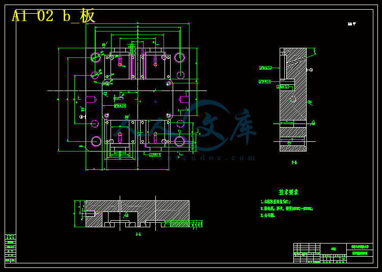
A1 02 b_板.exb
A1 03 定模板.exb
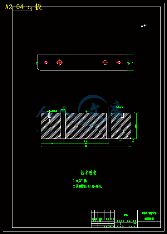
A2 04 c_板.exb
A3 05 顶杆_1.exb
A3 06 复位杆.exb
A3 07 浇口套_R1.exb
A3 08 晾衣叉产品.exb
A4 09 导杆.exb
A4 10 GB 导套.exb
A4 11 SB型限位钉.exb
A4 12 带肩导套.exb
A0 01 衣叉模具装配图.dwg
A1 02 b_板.dwg
A1 03 定模板.dwg
A2 04 c_板.dwg
A3 05 顶杆_1.dwg
A3 06 复位杆.dwg
A3 07 浇口套_R1.dwg
A3 08 晾衣叉产品.dwg
A4 09 导杆.dwg
A4 10 GB 导套.dwg
A4 11 SB型限位钉.dwg
A4 12 带肩导套.dwg
压缩包内文档预览:
预览图 预览图
编号:10109130    类型:共享资源    大小:3.48MB    格式:RAR    上传时间:2018-05-17 上传人:俊****计 IP属地:江苏
40
积分
关 键 词:
晾衣叉 塑料 注塑 模具设计 12 十二 cad 图纸 以及 说明书 仿单
资源描述:

摘  要


模具作为一种成型工具,其设计、制造水平的高低,直接关系到产品的质量与更新换代,是衡量一个国家产品制造水平的重要标志。

本文主要介绍的是晾衣叉注塑模具的设计方法。首先分析了晾衣叉制件的工艺特点,包括材料性能、成型特性与条件、结构工艺性等,并选择了成型设备。接着系统介绍了晾衣叉注塑模的分型面的选择、型腔数目的确定及布置,重点介绍了浇注系统、成型零件、侧向抽芯机构、合模导向机构、脱模机构、定距分型机构以及冷却系统的设计。然后选择标准模架和模具材料,并对注射机的工艺参数进行相关校核。最后对模具的工作原理进行阐述,以及在安装调试过程中可能出现的问题进行总结、分析,并给出了相应的解决方法。本文论述的晾衣叉注塑模具采用两板式结构,采用一模二腔的型腔布置,最后利用推杆将制件推出。


关键词:晾衣叉;注塑模;二板模;浇注系统


Abstract

Die as a tool for molding, its design, manufacture level are of direct bearing on the quality of products and replacement, an important indicator to measure a country's level of manufacturing.

The designing methods of injection mould of clothes fork are mainly introduced in this paper. First, the technological characteristics are analyzed, including material properties, forming characteristics and conditions, the process of the structure,  the forming equipment is selected. Then the parting line is selected, the number of cavities is determined. The specific introduction are made on gating system, cooling system, Molding parts, Steering mechanism,  moulding mechanism, and spacer parting institutions. Then the standard mould bases and mould materials are selected, and the technological parameters of the forming equipment is checked. Finally, problems that may emerge during the mold installation process are analyzed and the appropriate solutions are provided.Two pence mould is used on the design of charger shell. there are two cavities in this mould, finally a stripper plate is used to push off the clothes fork.


Keyword: Clothes fork; Injection mould; Two pence mould; Gating system; 


目    录

引言 1

1  塑件结构及尺寸 3

1.1 本塑件的材料分析 3

1.2 本塑件的工艺参数 4

1.3 本塑件的产品结构 4

1.4 塑件的公差 5

1.5 塑件的壁厚 5

1.6 塑件的脱模斜度 6

2  模具结构的设计 7

2.1 确定型腔数目的方法 7

2.2 型腔排列方式的确定 8

3  注射机型号的确定 8

3.1 注塑机定义 8

3.2 注塑机的类型 9

3.3 注塑机的结构 9

3.4 注塑机的选择 10

3.4.1所需注射量的计算、塑件质量、体积计算 10

3.4.2浇注系统凝料体积的初步估算 11

3.5 注塑机的校核 11

3.5.注射压力校核 11

3.5.2锁模力校核 12

3.5.3开模行程和模板安装尺寸校核 12

4  成型零件的设计 13

4.1 分型面的设计 13

4.2 成型零部件的结构设计 14

4.2.1型芯和型腔的结构设计 14

4.2.2注射模强度要求 15

4.3 型芯型腔的确定 16

5  侧向分型与抽芯机构 16

5.1 侧向抽芯机构的分类及组成 16

5.2 确定抽芯距 18

5.3 抽芯力的计算 18

5.4 斜导柱设计 20

6  浇注系统的设计 21

6.1 浇注系统的组成 21

6.2 浇注系统的作用 21

6.3 浇注系统设计影响因素 21

6.4 主流道的设计 22

6.4.1主流道的材料 23

6.4.2主流道的表面精度 23

6.5 分流道设计 23

6.6 浇口设计 25

6.6.1浇口的选用 26

6.6.2浇口位置的选用 26

6.6.3浇注系统的平衡 28

6.6.4排气的设计 28

7  标准模架的选取 28

8  合模导向机构的设计 30

8.1 导柱导向机构设计要点 30

9  脱模机构的设计 32

9.1 脱模机构设计的总原则 32

9.2 推杆设计 32

9.2.1推杆的形状 32

9.2.2推杆的位置和布局 33

9.3 推件板设计的要点 33

10  冷却系统的设计 34

10.1 冷却系统的计算 34

10.2 冷却系统的设计准则 34

11  典型零件的制造工艺 35

11.1 浇口套加工 35

11.2 定模座板加工 36

11.3 动模模套加工 37

11.4 导柱的加工 38

12  结语 39

谢 辞 40

参考文献 41


引言

作为工业生产基础工艺装备的模具,在国民经济中占有重要的地位,模具技术也已成为衡量一个国家产品制造水平的重要标志之一。     

第十一五规划中指出,模具是工业生产的基础工艺装备,国民经济的五大支柱产业——机械、电子、汽车、石化、建筑都要求模具工业发展与之相适应。模具因其生产效率高、产品质量好、材料消耗低、生产成本低而获得广泛应用,与其他加工制造业所无法比拟的。从工业产品生产行业看,模具是现代工业,特别是汽车、摩托车、航空、仪表、仪器、医疗器械、电子通讯、兵器、家用电器、五金工具、日用品等工业必不可少的工艺装备。据资料统计,利用模具制造的零件数量,在飞机、汽车、摩托车、拖拉机、电机、电器、仪器仪表等机电产品中占80%以上;在电脑、电视机、摄像机、照相机、录像机、传真机、电话及手机等电子产品中占85%以上;在电冰箱、洗衣机、空调、微波炉、吸尘器、电风扇、自行车、手表等轻工业产品中占90%以上;在子弹、枪支等兵器产品中占95%以上。


内容简介:
*,Departmeaccepted21In metal cutting, the problems need to be well analyzed in order to take precautions before any unexpected results are encoun-The objective of modern manufacturing is to have ious materials 2.andassuchnotanegativeprocessiftheanswersofwhen,how much and what type is known. There are certaintypesof wear mechanismsondierent typesofmetalcut-ting processes and similar/dierent types of problems areencountered as a result of these mechanisms. If these*Corresponding author. Tel.: +90 224 4428176; fax: +90 2244428021.E-mail addresses: cemal.tr (M.C. Cakir), cavdar.tr (K. Cavdar).1Tel.: +90 224 4428176; fax: +90 224 4428021.Materials and Design 27 (2006)Materials0261-3069/$ - see front matter C211 2005 Elsevier Ltd. All rights reserved.ecient control over the organizational facilities in or-der to produce high quality products at lower priceswithin a shorter time period. To achieve better qualityat a lesser price, every attention has to be paid in themanufacturing division by employing better cuttingtools, inserts and high precision machines, etc. 1. How-ever, this is not sucient for productivity in most of thecases. Choosing the right tool for the right job is impor-tant, but tool wear should also be considered for moreMetal cutting is a chip forming process. Although theprocess is directed at cutting metal to shape and size, thishas to be done by creating defined chips. The chip-form-ing process means that a fresh metal interface is contin-ually produced and forced at very high pressure andtemperature along the tool material 3. The zones pro-duced make it an attractive environment for diusionand chemical reactions of metal. All cutting tools areworn during machining and continue to do so until theycome to the end of their tool-life. Tool wear is inevitabletered. This process plays a significant role in achieving consistent quality and in controlling the overall cost of manufacturing. How-ever, it is a dicult task that needs an expert who has a great deal of information and experience in metal cutting. In the presentpaper, a knowledge-based expert system (COROSolve) that investigates problems that are encountered in three main metal cuttingareas: turning, milling and drilling is developed. A great deal of metal cutting operations such as external/internal turning with neg-ative/positive inserts, aluminum turning, parting bars/tubes, grooving, profiling, recessing and threading operations in turning; facemilling, square shoulder milling, end milling, multi-purpose milling and side and face milling operations in milling; and drilling oper-ations that use solid drills or drills with indexable inserts in drilling are taken into consideration. COROSolve gives recommenda-tions for the cutting data (i.e., cutting speed, depth of cut, and feed) and updates the problem, cause and remedy database, thus thenumber of problems that the system can handle is increased.C211 2005 Elsevier Ltd. All rights reserved.Keywords: Metal cutting problems; Expert systems; KBS; Tool wear1. Introduction ecient manufacturing. In the literature, many publica-tions do exist on the tool wear in manufacturing of var-Development of a knowledge-basedsolving metal cuttingM. Cemal CakirUludag University, Mechanical EngineeringReceived 8 September 2004;Available onlineAbstractdoi:10.1016/j.matdes.2005.01.022expert system forproblemsKadir Cavdar1nt, Gorukle 16059, Bursa, Turkey31 January 2005March 2005/locate/matdes10271034 training technical personnel in the design and evalua-tion of energy cogeneration plants 6; configuring paper feeding mechanisms 7; carrying out automatic re-meshing during a finite-elements analysis of forging deformation 8; storing, retrieving and adapting planar linkagedesigns 9; designing additive formulae for engine oil products10; selecting cutting tools or cutting data 1113.Several potential research areas were identified withrespect to expert systems in manufacturing 14,15.Kojiyama et al. 16 have discussed in their articles thata framework for machining operation planning systems,in which machining know-how extracted and organizedfrom electronic tool catalogs and machining instancedatabases available in the Internet environment plays aprincipal role. On the use of reference machining datacan be constitute, which is derived from the investiga-tion of tool catalogs, related international standards,reference textbooks, and handbooks.M.C. Cakir, K. Cavdar / Materials and Design 27 (2006) 10271034 1029Fig. 2. Inputs of the software.The application of Mookherjee and Bhattacharyya11 on expert system in the general turning and mill-ing operation is very useful for solving some of thechallenging problems presently faced by manufactur-ing engineers during the integration of CAD and var-ious CNC machining centers. Jiang et al. 17 havedeveloped an expert system to optimize the millingoperations for prismatic components. They havedescribed a new GT based coding scheme that repre-sents the surfaces to be machined of prismaticcomponents.Limsombutanan 18 has presented an algorithm toselect the cutter size and tool orientation in 5-axis sur-face machining that can act as a holon. Milling the sur-face is divided in to three phases, namely, roughing,semi-roughing and finishing. This algorithm selects thebest tool and plans the tool path autonomously for abicubic (convexconcave) surface based on analysis ofthe curvature.The main objective of the present paper is to buildsuch system that covers most of the major metal cuttingproblems and helps the people who are involved in metalcutting to improve the quality.3. A knowledge-based expert system for metal cuttingproblems3.1. Factors considered in solving metal cutting problemsMost of the problems in metal cutting are the resultof wear mechanisms. All cutting tools wear duringmachining and continue to do so until they come tothe end of their tool-life. Tool wear is inevitable and1030 M.C. Cakir, K. Cavdar / Materials and Design 27 (2006) 10271034Fig. 3. Flowchart of COROSolve.as such not a negative process if the answers of when,how much and what type is known. Thus, if the prob-lems resulted from tool wear as well as the other harmfulfactors eecting the machining operations are well ana-lyzed, it could be possible to find the right solutions toeach of them. This would reduce the unproductive faultsearching time, therefore reduce machining time, unpro-ductive stoppage times of machine tools, machining costand therefore increase the eciency of the process.Architecture of the expert system used in solving metalcutting problems is given in Fig. 1. Inputs that are takeninto consideration by the software are given in Fig. 2.3.2. Features of COROSolveThe software has been developed using DELPHI Vi-sual programming language. A major diculty in build-ing a consultation system was in capturing andexamining the knowledge elements used in the solutionof the problem. Based upon the design for solving prob-But although the tooling is right, if the machining con-ditions are not up to standard, especially as regards cut-ting data and general stability, problems arise andoptimum tool-life will not be reached. Incorrect cuttingdata, vibrations and lack of rigidity in tool holders andclamping are the main reasons of the metal cuttingproblems.Apart from being a problem solver, the softwareprovides cutting data recommendations for each typeof operation (types of operations were mentionedpreviously), for each type of material group (ISO P,M or K), for each type of application (rough, mediumor finish), for each type of machining condition (good,average, dicult) and displays the list of insertsavailable (Fig. 4). Here, it is not intended to findthe most suitable insert for the application, but tomonitor the starting values and the working rangesof cutting data (i.e., the cutting speed, feed rate andthe depth of cut) for the insert used in metal cutting.At this stage, it is possible to see the suitable gradeM.C. Cakir, K. Cavdar / Materials and Design 27 (2006) 10271034 1031lems in metal cutting study, once the operation type isselected, four major stages have been identified for eachtype of operation: Cutting data recommendations. Problem definition. Cutting data evaluation. Problem editor.The flowchart of the software is given in Fig. . Cutting data recommendationsThe selection of the right cutting tool is critical forachieving maximum productivity during machining.Fig. 4. Cutting data recommenthat was determined due to the selected operation,material group, application, etc. Besides, the list ofmaterials that each material group consist of can alsobe observed.Recommended cutting data values were acquiredfrom Sandvik Coromant 20, the cutting data fromthe other cutting tool vendors can be used as the rec-ommended values as well. Cutting data values dis-played are for a certain material hardness and for acertain tool-life. For any workpiece material havingdierent hardness values than the specified values,and the tool-life dierent than 15 min, the cutting dataprovided should be multiplied by the correction factors(see Table 1).dations.causesIncreased hardness0 +20 +40 +60 +80 +1001 0.91 0.84 0.77 0.72 0.671 0.91 0.84 0.78 0.73 0.681 0.95 0.9 0.86 0.82 0.7925 30 45 600.88 0.84 0.75 0.701032 M.C. Cakir, K. Cavdar / Materials and Design 27 (2006) 102710343.2.2. Analysing the metal cutting problemsFig. 5. Problems,Table 1Material hardness and tool life considerations 19ISO/ANSI HB Reduced hardnessC060 C040 C020P 180 1.44 1.25 1.11M 180 1.42 1.24 1.11K 260 1.21 1.13 1.06Tool life (min) 10 15 20Correction factor 1.11 1.0 0.93There are various dierent/similar types of problemsin metal cutting processes. In appearance some of theseproblems are identical and very hard to be distinguishedfrom each other. The classification of problem types hasbeen developed to form an important basis for assessingthe machining operation and to optimize productivityby getting the tool grade and machining conditions rightfor the type of cut and material. The right tool, goodstarting values for cutting data, expert support, ownexperience, good quality of workpiece materials and ma-chine conditions are important ingredients for success inmachining. Aggregation of problem lists from varioustool manufacturers is classified to form KBS used bythe software.The user analyses the metal cutting problems either inone or two stages: by straightforwardly picking outProblem Definition option from the menu or by checkingout the cutting data used in the metal cutting processfirst and accessing to the problem definition sectionafterwards. Problem Definition section displays the listof problems, their possible causes and the remedies withrespect to the causes. Once a problem is selected (i.e.,flank wear in turning or chip jamming in drill flutes indrilling), a picture that provides a clear definition tothe problem and the list of possible causes are displayed.Consequently once a possible cause is selected, the rem-edies are determined. More information about the prob-lem is obtained by clicking on ? (Fig. 5).3.2.3. Cutting data evaluationand remedies.In metal cutting, most of the problems are the resultof unsuitable cutting data for the application. Thus,before straightforward listing of the problems, the useris advised to check the cutting data for the operation,for the application and for the machining conditionsto find out whether the cutting speed, feed rate andthe cutting depth are correct for the length, thicknessand nose radius of the insert used. The Cutting Dataoption checks if the cutting data in the operation areright for the insert in use and this task is basically theFig. 6. Checking the cutting data.a newM.C. Cakir, K. Cavdar / Materials and Design 27 (2006) 10271034 1033comparison of the cutting data with the ideal values cal-culated from the multiplication of the catalogue valuesand the correction factors. If there is no match (thismeans the values of cutting data are not in the range)the user is advised to correct the cutting data. In millingand drilling only cutting speed and feed rate values areconsidered, in drilling this consideration takes the drilldiameter and the grade of the centre/periphery insertinto account (Fig. 6). In the figure, cutting data for facemilling of steel for medium feed rates (L for light, M formedium, H for heavy milling operations) are evaluatedand since the feed value is lower than the ideal valuescalculated for given hardness and tool life, a warningis displayed.Once the cutting data are reviewed (and corrected),Fig. 7. Addingaccessing to the problem definition section is the nextstep.Sincethecuttingdataarecorrected,thelistofcausesandtheremedieswillnowbedierentandnosuch causesasCuttingspeedistoohighorFeedrateistoolowwillnot be amongst the causes of the related problem.The software is capable of analysing more than 100types of problems in various types of operations andproviding remedies to the nearly 200 causes (340 reme-dies). The knowledge contained in the system has beencompiled from two main sources: from human expertsworking in the field of metal cutting and from thetechnical documents, catalogues or handbooks of vari-ous cutting tool producing companies 2. Problem editorThe knowledge contained in the system has beencompiled from two main sources: from human expertsworking in the field of manufacturing and from the tech-nical documents, catalogues or handbooks of variouscutting tool producing companies. The success of an ex-pert system is hidden in its expandable structure like ahuman expert who adds every new solution he comesacross to his knowledge and uses this knowledge in hisfuture analyses. Thus, COROSolve has an expandabledatabase structure that grows to handle more and moreproblems everyday.Since the system has a separate and modular knowl-edge base, it is very easy indeed to update the system bysimply getting into the database and editing the knowl-edge files. The more information the system contains,the more problems it can handle in metal cutting.Knowledge base is the heart of the system, therefore itis the task of a few people who are responsible fromthe production to add, delete or modify it. Thus, theuser needs to know the password to access to the knowl-edge base.remedy.Problem edit allows the new problems, picture andinformation files related to the problems, causes andthe remedies of the problems to be added to the knowl-edge base. Besides, it is possible to add new causes to theproblems, or new remedies to the causes that are alreadyexist in the knowledge base (Fig. 7).The system is multi-linguistic, therefore it is capableof handling the metal cutting problems both in Turkishand English. Once the language is determined, all theprogram menus and problem, cause and remedy listsare displayed in the language chosen.4. ConclusionsThis paper introduces an expert system approach forthe task of solving metal cutting problems in variousmachining operations. Since there are not many workexist in the literature about this subject and since thistype of system can mostly fulfil the requirements in me-tal cutting industry, the work described here can beconsidered as a useful piece of work. In manufacturingindustry, especially in small or medium-volume machineshops, incorrect cutting data are the main reason of theproblems. Tools were generally run at lower cutting datato make them last longer for less frequent changes. Thisthen obviously meant poor utilization of the metal cut-ting time. Since one of facilities that the system provideis the evaluation of the cutting data, it will help the userto choose the right speed, feed or the depth of cut for theapplication. If the cutting data are correct and the metalcutting problems are solved, the stoppages due to thebreakdowns will be shorten, good utilization of powercapacity will be achieved and the metal cutting time willtherefore be reduced. This means a great deal of reduc-tion in production cost.The system developed intends to educate the people2005;21(2):17583.5 Peers SMC, Tang MX, Dharmavasan S. A knowledge-basedplants. In: Proceedings of the third world congress on expertsystems, Seoul, Korea. February 1996. p. 3005.7 Koo DY, Han SH. Application of the configuration designmethods to a design expert system for paper feeding mechanism.In: Proceedings of the third world congress on expert systems,Seoul, Korea. February 1996. p. 4956.8 Yano H, Akashi T, Matsuoka T, Nakanishi K, Takata O,Horinouchi N. An expert systems to assist automatic remeshing inrigid plastic analysis. Toyota Tech Rev 1997;46:8792.9 Bose A, Gini M, Riley D. A case-based approach to planarlinkage design. Artif Intell Eng 1997;11:10719.10 Shi ZZ, Zhou H, Wang J. Applying case-based reasoning toengine oil design. Artif Intell Eng 1997;11:16772.11 Mookherjee R, Bhattacharyya B. Development of an expertsystem for turning and rotating tool selection in a dynamicenvironment. J Mater Process Technol 2001;13:30611.12 Wong SV, Hamouda AMS. Development of generic algorithm-based fuzzy rules design for metal cutting data selection. Robot1034 M.C. Cakir, K. Cavdar / Materials and Design 27 (2006) 10271034scheduling system for oshore structure inspection. In: Rzevski G,Adey RA, Russell DW, editors. Artificial intelligence in engineer-ing IX (AIEng 9), Computational Mechanics, Southampton,1994. p. 1818.6 Rosano FL, Valverde NK, De La Paz Alva C, Zavala JA.Tutorial expert system for the design of energy cogenerationin metal cutting industry as well. The pi
温馨提示:
1: 本站所有资源如无特殊说明,都需要本地电脑安装OFFICE2007和PDF阅读器。图纸软件为CAD,CAXA,PROE,UG,SolidWorks等.压缩文件请下载最新的WinRAR软件解压。
2: 本站的文档不包含任何第三方提供的附件图纸等,如果需要附件,请联系上传者。文件的所有权益归上传用户所有。
3.本站RAR压缩包中若带图纸,网页内容里面会有图纸预览,若没有图纸预览就没有图纸。
4. 未经权益所有人同意不得将文件中的内容挪作商业或盈利用途。
5. 人人文库网仅提供信息存储空间,仅对用户上传内容的表现方式做保护处理,对用户上传分享的文档内容本身不做任何修改或编辑,并不能对任何下载内容负责。
6. 下载文件中如有侵权或不适当内容,请与我们联系,我们立即纠正。
7. 本站不保证下载资源的准确性、安全性和完整性, 同时也不承担用户因使用这些下载资源对自己和他人造成任何形式的伤害或损失。
提示  人人文库网所有资源均是用户自行上传分享,仅供网友学习交流,未经上传用户书面授权,请勿作他用。
关于本文
本文标题:晾衣叉塑料注塑模具设计【12张CAD图纸和说明书】
链接地址:https://www.renrendoc.com/p-10109130.html

官方联系方式

2:不支持迅雷下载,请使用浏览器下载   
3:不支持QQ浏览器下载,请用其他浏览器   
4:下载后的文档和图纸-无水印   
5:文档经过压缩,下载后原文更清晰   
关于我们 - 网站声明 - 网站地图 - 资源地图 - 友情链接 - 网站客服 - 联系我们

网站客服QQ:2881952447     

copyright@ 2020-2024  renrendoc.com 人人文库版权所有   联系电话:400-852-1180

备案号:蜀ICP备2022000484号-2       经营许可证: 川B2-20220663       公网安备川公网安备: 51019002004831号

本站为文档C2C交易模式,即用户上传的文档直接被用户下载,本站只是中间服务平台,本站所有文档下载所得的收益归上传人(含作者)所有。人人文库网仅提供信息存储空间,仅对用户上传内容的表现方式做保护处理,对上载内容本身不做任何修改或编辑。若文档所含内容侵犯了您的版权或隐私,请立即通知人人文库网,我们立即给予删除!