论文.doc

照相机外壳注塑模具设计【20张CAD图纸和说明书】

收藏

压缩包内文档预览:(预览前20页/共58页)
预览图 预览图 预览图 预览图 预览图 预览图 预览图 预览图 预览图 预览图 预览图 预览图 预览图 预览图 预览图 预览图 预览图 预览图 预览图 预览图
编号:10118844    类型:共享资源    大小:3.04MB    格式:RAR    上传时间:2018-05-23 上传人:俊****计 IP属地:江苏
40
积分
关 键 词:
照相机 外壳 注塑 模具设计 20 cad 图纸 以及 说明书 仿单
资源描述:

摘 要

塑料注射模具是工业生产的基础工艺设备,在电子、汽车、电机、电器、仪表、家电和通讯等产品中,60%~80%的零部件,都要依靠模具成形。它不仅直接影响工业产品的水平,也是一个国家工业化程度和机械制造工业技术水平的综合体现。

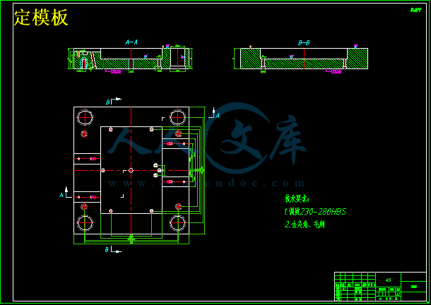
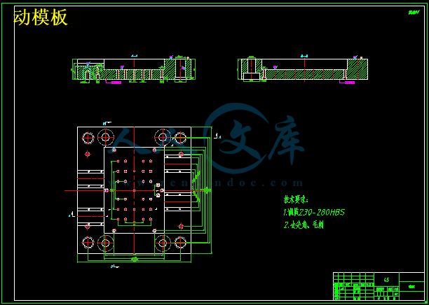
照相机外壳是一类体积适中,形状、结构较为简单的塑料零件。根据照相机外壳的结构确定模具的结构方案,利用塑件的三维零件图,确定模具的主要结构方式,进而画出其模具的CAD装配图和零件图。

通过对塑件的结构分析,本次设计采用一模四腔设计,滑块侧抽芯机构,实现照相机外壳侧孔的生成;采用侧浇口形式;塑件的体积适中,采用推杆推出实现脱料。采用此模具结构不仅可以保证塑件的表面要求和尺寸精度,而且生产率高、成本低、结构简单,可行性强,是一副实用性很强的模具。


关键词:注塑模具;照相机外壳;塑件;斜滑块


The camera shell injection mold design

Abstract

Plastic injection mould is the basis of process equipment in industrial production, in the electronic, automobile, motor, electrical appliance, instrument, home appliances and communication products, 60%-80% of the parts, must rely on forming die. It not only directly affect the level of industrial products, is a comprehensive reflection of a country industrialization and machinery manufacturing industry technical level.

Camera housing is a kind of medium in size, shape, simple structure of plastic parts. According to the camera shell structure determine the structure scheme of the mould, plastic parts of the 3D part drawings, the main structure of dies, and then draw the production of plastic parts CAD parts and assembly plans.

Through the structural analysis of plastic parts, the design adopts the design of a mold four cavity, slanted slide block core-pulling mechanism, realization of generating camera housing side hole; the side gate; moderate volume of plastic parts, the push rod is introduced to achieve stripping. The die structure can not only ensure the surface requirements of plastic parts and precision, and high productivity, low cost, simple structure, strong feasibility, is a very practical mould.


Key words: injection mold; camera housing; plastic parts; Oblique slippery


主要符号表

G——注塑机的实际最大注射量,或g;

T——注塑机的额定锁模力,t;

q——熔融塑料在模腔内的压力,;

S——注射机开模行程,mm;

——塑料的平均收缩率;

——制品的设计公差;

——模具制造公差;

——型芯或成型孔中心距;

——制品孔或凸台中心距;

——动模板受的总压力,MPa;

F——塑件浇注系统在动模上的投影面积,;

P——型腔压力,一般取25~45MPa,取32MPa;

E——塑料的弹性模量,;

——塑料的成型收缩率,查表取;

——型芯的脱模斜度,为1°

——塑料的泊松比,查表得

——与及有关的系数,

——塑料与型芯间的静摩擦因数;

——推杆最大应力,

c——型芯成型部分的平均周长,mm;

h——型芯被塑料包紧部分的长度,mm;

p——单位面积的包紧力,MPa

——推杆最大应力,

——抽芯力,N

——冷却介质的体积流量,;

——单位时间(每分钟)内注入模具中的塑料质量,

——单位重量的塑件在凝固时所放出的热量,

——冷却介质的密度,

——冷却介质的比热容,

——冷却介质的体积流量,

——冷却管道孔壁与冷却介质之间的传热膜系数,

——模温与冷却介质温度之间的平均温差,℃


目  录

1 绪论 1

1.1概述 1

1.2模具发展现状及发展方向 1

1.2.1塑料模具工业的发展现状及方向 1

1.3本课题的内容和具体要求 3

1.3.1本课题的内容 3

1.3.2具体要求 3

2 模具方案的论证和选择 4

2.1 ABS注射成型的原理及工艺过程 4

2.1.1注射成型的原理 4

2.1.2注塑成型工艺过程 4

2.1.3注射成形工艺参数 4

2.2 注塑模具的基本组成 4

2.2.1基本组成 5

2.2.2注塑模具装配图的技术要求 5

3 注射机的选择和型腔数目的确定及分布 6

3.1塑件材料的选择 6

3.2塑件的基本资料 6

3.2.1产品资料 6

3.3ABS注射工艺性 6

3.4型腔数目的确定及分布 7

3.5注射机的选择 8

3.5.1注射量的校核 8

3.5.2锁模力的校核 8

3.5.3最大注射容量校核 9

3.5.4注射压力校核 9

3.5.5模具厚度的校核 9

3.5.6开模行程的校核 9

3.6分型面的选择原则 10

3.6.1分型面的选择原则 10

3.6.2分型面的分类 10

3.6.3分型面的确定 10

4 排气系统的设计 12

5 浇注系统的设计 13

5.1浇注系统设计的原则 13

5.1.1了解塑料的成型特性 13

5.1.2布局合理 13

5.1.3防止型芯和塑件的变形 13

5.1.4减小流程及塑料耗量 13

5.1.5排气良好 13

5.1.6修整方便,保证塑件外观质量 13

5.2主流道设计 13

5.3冷料穴设计 14

5.4分流道设计 14

5.5浇口设计 14

5.5.1浇口的主要作用 15

5.5.2浇口位置的选择原则 15

5.6浇口套的选择 15

6 拉料杆的设计 16

7 成型零件的设计 17

7.1凹模、凸模的结构设计 17

7.1.1凹模的结构设计 17

7.1.2凸模的结构设计 17

7.2成形零件钢材选用 17

7.2.1成形零件对钢材的要求 17

7.3成型零件工作尺寸 17

7.3.1工作尺寸分类和确定 17

7.3.2影响塑件尺寸精度的因素如下。 18

7.4成型零件工作尺寸的计算 19

7.4.1凹模尺寸计算 19

7.4.2凸模和型芯的尺寸计算 19

7.4.3型芯中心距或成型孔中心距尺寸计算 20

7.5动模板强度校核 20

8 脱模机构的设计 22

8.1脱模机构的基本要求 22

8.2脱模机构的设计原则 22

8.3推出机构的确定 22

8.4脱模力的计算 22

8.5推杆强度的校核 23

8.6复位杆的设计 24

9 导向机构的设计 26

9.1导向机构的作用和设计原则 26

9.1.1导向机构的作用 26

9.1.2设计原则 26

9.2导柱导套的设计 26

9.2.1导柱的设计 27

9.2.2导套的设计 27

9.3导向孔的布局 27

10 抽芯机构的设计 29

10.1抽芯机构概述 29

10.2抽芯机构的确定 29

10.3斜导柱抽芯机构的结构设计 29

10.3.1斜导柱分型与抽芯机构 29

10.3.2斜导侧向分型与抽芯机构应具备以下基本功能 29

10.4斜导柱抽芯机构的有关参数计算 29

10.4.1抽芯距S 30

10.4.2斜导柱倾斜角的确定 30

10.4.3抽芯力的计算 30

10.4.4斜导柱直径的计算 30

10.4.5斜导柱长度的计算 31

10.5斜导柱的结构 31

10.6滑块的设计 32

10.7楔紧块的设计 32

10.8导滑槽的设计 33

10.8.1设计要点 33

10.8.2导滑槽和滑块的配合关系 33

10.8.3导滑槽的结构 33

11 温度调节系统的设计 34

11.1温度调节对塑件质量的影响 34

11.2温度调节系统的要求 34

11.3模具温度对制品质量的影响 34

11.3.1变形 34

11.3.2尺寸精度 34

11.3.3力学性能 34

11.4模具冷却装置的设计 34

11.4.1冷却装置的设计要点 34

11.4.2确定冷却系统的参数 35

11.4.3水嘴的结构形式 37

11.4.4冷却水道的结构 37

12 其它结构零部件设计 38

13 模具的材料 39

13.1塑料模具对模具材料的要求 39

13.2塑料模具常用材料 39

13.3模具的淬火硬度 39

13.4模具的表面粗糙度 39

13.5热处理的选择 39

13.6模具材料性能分析 40

14 模具的可行性分析 41

14.1模具的特点 41

14.2经济效率与市场前景分析 41

15 结论 42

参考文献 43

致  谢 44

毕业设计(论文)知识产权声明 45

毕业设计(论文)独创性声明 46


1  绪论

1.1概述

塑料注射模具是工业生产的基础工艺设备。振兴和发展我国的模具工业,日益受到人们的重视和关注。在电子、汽车、电机、电器、仪表、家电和通讯等产品中,60%~80%零部件,都要依靠模具成形。用模具生产制作所表现出来的高精度、高复杂程度、高一致性、高生产率和低消耗,是其他加工制造方法所不能比拟的。模具又是“效率放大器”,用模具生产的最终产品的价值,往往是模具自身价值的几十倍、上百倍。因此,塑料模具技术,特别是制造精密、复杂、大型模具的技术,已成为衡量一个国家机械制造水平的重要标志之一。


内容简介:
_ Corresponding author: Alban Agazzi, Universit de Nantes-Laboratoire de thermocintique de Nantes, La Chantrerie, rue Christian Pauc, BP 50609, 44306 Nantes cedex 3-France, phone : +332 40 68 31 71, fax :+332 40 68 31 41 email : alban.agazziuniv-nantes.fr A METHODOLOGY FOR THE DESIGN OF EFFECTIVE COOLING SYSTEM IN INJECTION MOULDING A.Agazzi1*, V.Sobotka1, R. Le Goff2, D.Garcia2,Y.Jarny11Universit de Nantes, Nantes Atlantique Universits, Laboratoire de Thermocintique de Nantes, UMR CNRS 6607, rue Christian Pauc, BP 50609, F-44306 NANTES cedex 3, France 2Ple Europen de Plasturgie, 2 rue Pierre et Marie Curie, F- 01100 BELLIGNAT, France ABSTRACT: In thermoplastic injection moulding, part quality and cycle time depend strongly on the cooling stage. Numerous strategies have been investigated in order to determine the cooling conditions which minimize undesired defects such as warpage and differential shrinkage. In this paper we propose a methodology for the optimal design of the cooling system. Based on geometrical analysis, the cooling line is defined by using conformal cooling concept. It defines the locations of the cooling channels. We only focus on the distribution and intensity of the fluid temperature along the cooling line which is here fixed. We formulate the determination of this temperature distribution, as the minimization of an objective function composed of two terms. It is shown how this two antagonist terms have to be weighted to make the best compromise. The expected result is an improvement of the part quality in terms of shrinkage and warpage. KEYWORDS: Inverse problem, heat transfer, injection moulding, cooling design 1 INTRODUCTION In the field of plastic industry, thermoplastic injection moulding is widely used. The process is composed of four essential stages: mould cavity filling, melt packing, solidification of the part and ejection. Around seventy per cent of the total time of the process is dedicated to the cooling of the part. Moreover this phase impacts directly on the quality of the part 12. As a consequence, the part must be cooled as uniformly as possible so that undesired defects such as sink marks, warpage, shrinkage, thermal residual stresses are minimized. The most influent parameters to achieve these objectives are the cooling time, the number, the location and the size of the channels, the temperature of the coolant fluid and the heat transfer coefficient between the fluid and the inner surface of the channels. The cooling system design was primarily based on the experience of the designer but the development of new rapid prototyping process makes possible to manufacture very complex channel shapes what makes this empirical former method inadequate. So the design of the cooling system must be formulated as an optimization problem. 1.1 HEAT TRANSFER ANALYSIS The study of heat transfer conduction in injection tools is a non linear problem due to the dependence of parameters to the temperature. However thermophysical parameters of the mould such as thermal conductivity and heat capacity remain constant in the considered temperature range. In addition the effect of polymer crystallisation is often neglected and thermal contact resistance between the mould and the part is considered more often as constant. The evolution of the temperature field is obtained by solving the Fouriers equation with periodic boundary conditions. This evolution can be split in two parts: a cyclic part and an average transitory part. The cyclic part is often ignored because the depth of thermal penetration does not affect significantly the temperature field 3. Many authors used an average cyclic analysis which simplifies the calculus, but the fluctuations around the average can be comprised between 15% and 40% 3. The closer of the part the channels are, the higher the fluctuations around the average are. Hence in that configuration it becomes very important to model the transient heat transfer even in stationary periodic state. In this study, the periodic transient analysis of temperature will be preferred to the average cycle time analysis. It should be noticed that in practice the design of the cooling system is the last step for the tool design. Nevertheless cooling being of primary importance for the quality of the part, the thermal design should be one of the first stages of the design of the tools. DOI 10.1007/s12289-010-0695-2 Springer-Verlag France 2010Int J Mater Form (2010) Vol. 3 Suppl 1: 16 131.2 OPTIMIZATION TECHNIQUES IN MOULDING In the literature, various optimization procedures have been used but all focused on the same objectives. Tang et al. 4 used an optimization process to obtain a uniform temperature distribution in the part which gives the smallest gradient and the minimal cooling time. Huang 5 tried to obtain uniform temperature distribution in the part and high production efficiency i.e a minimal cooling time. Lin 6 summarized the objectives of the mould designer in 3 facts. Cool the part the most uniformly, achieve a desired mould temperature so that the next part can be injected and minimize the cycle time. The optimal cooling system configuration is a compromise between uniformity and cycle time. Indeed the longer the distance between the mould surface cavity and the cooling channels is, the higher the uniformity of the temperature distribution will be 6. Inversely, the shorter the distance is, the faster the heat is removed from the polymer. However non uniform temperatures at the mould surface can lead to defects in the part. The control parameters to get these objectives are then the location and the size of the channels, the coolant fluid flow rate and the fluid temperature. Two kinds of methodology are employed. The first one consists in finding the optimal location of the channels in order to minimize an objective function 47. The second approach is based on a conformal cooling line. Lin 6 defines a cooling line representing the envelop of the part where the cooling channels are located. Optimal conditions (location on the cooling and size of the channels) are searched on this cooling line. Xu et al. 8 go further and cut the part in cooling cells and perform the optimization on each cooling cell. 1.3 COMPUTATIONAL ALGORITHMS To compute the solution, numerical methods are needed. The heat transfer analysis is performed either by boundary elements 7 or finite elements method 4. The main advantage of the first one is that the number of unknowns to be computed is lower than with finite elements. Only the boundaries of the problem are meshed hence the time spent to compute the solution is shorter than with finite elements. However this method only provides results on the boundaries of the problem. In this study a finite element method is preferred because temperatures history inside the part is needed to formulate the optimal problem. To compute optimal parameters which minimize the objective function Tang et al. 4 use the Powells conjugate direction search method. Mathey et al. 7 use the Sequential Quadratic Programming which is a method based on gradients. It can be found not only deterministic methods but also evolutionary methods. Huang et al. 5 use a genetic algorithm to reach the solution. This last kind of algorithm is very time consuming because it tries a lot of range of solution. In practice time spent for mould design must be minimized hence a deterministic method (conjugate gradient) which reaches an acceptable local solution more rapidly is preferred. 2 METHODOLOGY 2.1 GOALS The methodology described in this paper is applied to optimize the cooling system design of a T-shaped part (Figure 1). This shape is encountered in many papers so comparison can easily be done in particularly with Tang et al. 4. Figure 1 : Half T-shaped geometryBased on a morphological analysis of the part, two surfaces 1 and 3 are introduced respectively as the erosion and the dilation (cooling line) of the part (Figure 1). The boundary condition of the heat conduction problem along the cooling line 3 is a third kind condition with infinite temperatures fixed as fluid temperatures. The optimization consists in finding these fluid temperatures. Using a cooling line prevents to choose the number and size of cooling channels before optimization is carried out. This represents an important advantage in case of complex parts where the location of channels is not intuitive. The location of the erosion line in the part corresponds to the minimum solidified thickness of polymer at the end of cooling stage so that ejectors can remove the part from the mould without damages. 2.2 OBJECTIVE FUNCTION In cooling system optimization, the part quality should be of primarily importance. Because the minimum cooling time of the process is imposed by the thickness and the material properties of the part, it is important to reach the optimal quality in the given time. The fluid temperature impacts directly the temperature of the mould and the part, and for turbulent fluid flow the only control parameter is the cooling fluid temperature. In the following, the parameter to be optimized is the fluid temperature and the determination of the optimal distribution around the part is formulated as the minimization of an objective function S composed of two terms computed at the end of the cooling period (Equation (1). The goal of the first term S1is to reach a temperature level along the erosion of the part. The second term S2used in many works 47 aims to homogenize the temperature distribution at the surface of the part and therefore to reduce the components of 14thermal gradient both along the surface 2 and through the thickness of the part. These two terms are weighted by introducing the variablerefT . It must be noted that when refT the criterion is reduced to the first term. On the contrary the weight of the second term is increased when 0refT . ()+=222112. dTTTdTTTTTSrfejecinjejecfluid(1)ejecT : Ejection temperature, injT : Injection temperature, refT : Reference temperature, infT : Fluid temperature, T : Temperature field computed with the periodic conditions () ),0(,0 XtTXTf+=21X , and ft,0 is the cooling period, =dTT22.1: Average surface temperature of the part at the ejection time ft . 3 NUMERICAL RESULTS Numerical results are compared with those of Tang et al 4 who consider the optimal cooling of the T-shaped part by determining the optimal location of 7 cooling channels and the optimal fluid flow rate of the coolant. The first step was to reproduce their results (left part of Figure 2) obtained with the following conditions (case w=0.75 in 4): KTfluid303= , fluid flow rate scmQ /3643= in each cooling channels, s 5.23=ft . Figure 2: Geometry Tang (left) and cooling line (right) Case 1: Cooling line versus finite number of channels for a constant fluid temperature (fluidT ). The average distance ( cmd 5.1= ) between the 7 channels and the part surface in the cooling system determined by Tang is adopted in our system for locating the cooling line 3 . Moreover, the fluid temperature and the heat transfer coefficient values issued from Tang are imposed on the dilation of the part 3 . In Figure 3 the temperature profiles along the part surface 2 are compared at the ejection time ft . All the temperature profiles along the surfaces 3,2,1 = iiare plotted counter-clockwise only on the half part from iAto iB (Figure 1) and at the ejection time. We observe that the magnitude of the temperature is less uniform with the cooling line than with the 7 channels (15K instead of 5K). Hence the optimal cooling configuration computed with a finite number of channels is better than this with the cooling line and it will be then considered as a reference. Figure 3: Temperature profiles along the part surface2Case 2: Cooling line with a variable fluid temperature ( )(sTfluid) and the weighting factor refT . The fluid temperatures )(sTfluidare computed by minimizing the objective function of Equation 1 where the second term is ignored. The results are plotted in Figures 4 and 5. Figure 4: Temperature profiles along the erosionFigure 5: Temperature profiles along the part surface In Figure 4 the temperature profile on the erosion is much uniform and close to the ejection temperature with our method (-511.79.10S = ) than with Tangs method (-512.32.10=S ). However in both cases a peak remains between 0.12m and 0.14m which corresponds to the top of the rib (B1in Figure 1). This hotspot is due to the geometry of the part and is very difficult to cool. Nevertheless in Figure 5 we notice that the profile of temperature at the part surface is less uniform than in 15case 1 (20K instead of 15K). In conclusion, the first term is not sufficient to improve the homogeneity at the part surface but it is adequate for achieving a desired level of temperature in the part. Case 3: Cooling line with ( )(sTfluid) and the weighting factors KTref10= and KTref100= . The fluid temperatures )(sTfluidare now computed by minimizing the objective function of Equation 1 with KTref10= and KTref100= . Results are plotted in Figures 6 and 7. Figure 6: Temperature profiles along the part surface Figure 7: Temperature profiles along the erosion The influence of the term S2is shown in Figure 6. This term makes the surface temperature of the part uniform. Indeed in case KTref10= temperature is quasi-constant all over the surface 2 except for the hotspot as explained previously. However for this value of refT , the temperature on the erosion is not acceptable, the mean temperature being too high (340K for a desired level of 336 K). Then the second term improves the homogeneity at the interface but hedges the solution. Making uniform the temperature at the interface meanwhile extracting the total heat flux needed to obtain a desired level of temperature in the part, become antagonistic problems if this level is too low. The best solution will be a compromise between quality and efficiency. For example, by setting KTref100= the level of temperature (ejecT ) in the part is reached whereas the solution becomes less uniform than with the value of KTref10= . Nonetheless this solution remains more uniform than the solution given by Tang. The optimal fluid temperature profile along the dilation of the half part is plotted (Figure 8). Figure 8: Optimal fluid temperature profile 4 CONCLUSIONS In this paper, an optimization method was developed to determine the temperature distribution on a cooling line to obtain a uniform temperature field in the
温馨提示:
1: 本站所有资源如无特殊说明,都需要本地电脑安装OFFICE2007和PDF阅读器。图纸软件为CAD,CAXA,PROE,UG,SolidWorks等.压缩文件请下载最新的WinRAR软件解压。
2: 本站的文档不包含任何第三方提供的附件图纸等,如果需要附件,请联系上传者。文件的所有权益归上传用户所有。
3.本站RAR压缩包中若带图纸,网页内容里面会有图纸预览,若没有图纸预览就没有图纸。
4. 未经权益所有人同意不得将文件中的内容挪作商业或盈利用途。
5. 人人文库网仅提供信息存储空间,仅对用户上传内容的表现方式做保护处理,对用户上传分享的文档内容本身不做任何修改或编辑,并不能对任何下载内容负责。
6. 下载文件中如有侵权或不适当内容,请与我们联系,我们立即纠正。
7. 本站不保证下载资源的准确性、安全性和完整性, 同时也不承担用户因使用这些下载资源对自己和他人造成任何形式的伤害或损失。
提示  人人文库网所有资源均是用户自行上传分享,仅供网友学习交流,未经上传用户书面授权,请勿作他用。
关于本文
本文标题:照相机外壳注塑模具设计【20张CAD图纸和说明书】
链接地址:https://www.renrendoc.com/p-10118844.html

官方联系方式

2:不支持迅雷下载,请使用浏览器下载   
3:不支持QQ浏览器下载,请用其他浏览器   
4:下载后的文档和图纸-无水印   
5:文档经过压缩,下载后原文更清晰   
关于我们 - 网站声明 - 网站地图 - 资源地图 - 友情链接 - 网站客服 - 联系我们

网站客服QQ:2881952447     

copyright@ 2020-2024  renrendoc.com 人人文库版权所有   联系电话:400-852-1180

备案号:蜀ICP备2022000484号-2       经营许可证: 川B2-20220663       公网安备川公网安备: 51019002004831号

本站为文档C2C交易模式,即用户上传的文档直接被用户下载,本站只是中间服务平台,本站所有文档下载所得的收益归上传人(含作者)所有。人人文库网仅提供信息存储空间,仅对用户上传内容的表现方式做保护处理,对上载内容本身不做任何修改或编辑。若文档所含内容侵犯了您的版权或隐私,请立即通知人人文库网,我们立即给予删除!