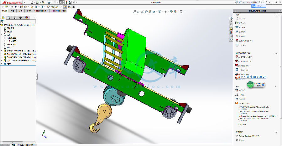
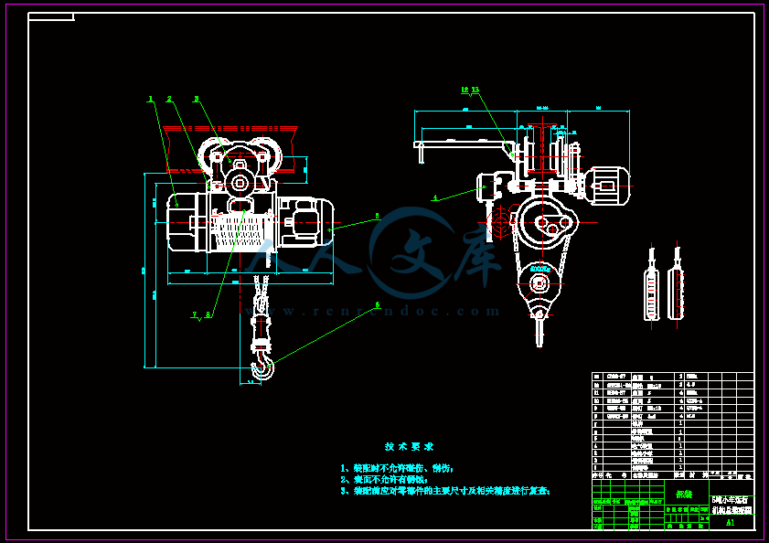
5T单梁桥式起重机钢结构设计含3D【全套含有CAD图纸三维建模】
收藏
资源目录

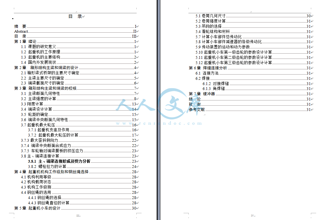
压缩包内文档预览:(预览前20页/共65页)
编号:10134176
类型:共享资源
大小:8.16MB
格式:ZIP
上传时间:2018-06-01
上传人:机****料
认证信息
个人认证
高**(实名认证)
河南
IP属地:河南
200
积分
- 关 键 词:
-
桥式起重机
钢结构
设计
全套
含有
cad
图纸
三维
建模
- 资源描述:
-


- 内容简介:
-
包含 CAD 图纸和三维建模及说明书,咨询 Q 197216396 或 11970985本科毕业论文(设计)论 文 题 目: 5T 单梁桥式起重机钢结构设计学 院:专 业 、班 级:学 生 姓 名:指导教师(职称)包含 CAD 图纸和三维建模及说明书,咨询 Q 197216396 或 11970985I摘 要起重机作为物料搬运、装卸或用于安装的机械设备可以减轻或代替人们的体力劳动提高劳动生产率。它被广泛应用于国民经济的各个领域之中。随着时代的发展制造工厂和装卸作业场所开始转向室内使桥式起重机占据了主导地位。桥式起重机主要应用于大型加工企业如钢铁、冶金和建材等行业完成生产过程中的起重和吊装等工作。设计一个满足 5T 承载量的钢体结构,主要设计计算端梁、横梁的尺寸,并对其进行校核,对小车的运行结构进行了设计。完善 CAD 工程图以及三维图,使其在实际生产操作中能够准确稳定的完成各项工作,提高生产效率,并成功投入到市场,桥式起重机由桥架、大车运行机构、小车运行机构和电气设备构成。在系统整体设计中采用传统布局的典型结构,桥式起重机是一种提高劳动生产率重要物品搬运设备,主要适应车间物品搬运、设备的安装与检修等用途。起升机构滑轮组采用双联滑轮组,重物在升降过程中没有水平移动,起升过程平稳,且钢丝绳的安装和更换容易。相应的卷绕装置采用单层卷筒,有与钢丝绳接触面积大,单位压力低的优点。在起升机构中还涉及到钢丝绳、减速器、联轴器、电动机和制动器的选择等。5t 桥式起重机小车运行机构主要由减速器,运行机构,卷筒装置,吊钩装置,联轴器,限位器,锥形转子电动机等部分组成。本文根据设计任务书要求,主要对 5t 桥式起重机小车运行机构的总体方案选择和确定,然后对传动系统进行设计。根据设计要求和目的,参考 5t 桥式起重机小车运行机构首先对 5t 桥式起重机小车运行机构进行工艺分析,选择合理机构及装配方案,然后对减速器和电动机进行外形设计,钢丝绳的选用及强度验算,卷筒的参数计算及验算,再计算齿轮的传动比,确定各个齿轮的参数,进行强度计算,选择合理的轴承、键、轴套等各种零部件,画出总体装配图。最后对齿式弹性联轴器作了一些简明的阐述。关键词:起重机,5t 桥式起重机,小车运行机构,卷筒,吊钩包含 CAD 图纸和三维建模及说明书,咨询 Q 197216396 或 11970985IIAbstractCrane for material handling, loading and unloading or for the installation of machinery and equipment can reduce or replace physical labour productivity. It is widely used in various fields of the national economy. With the development of manufacturing facilities and places of loading and unloading operations are turning to indoor cranes occupies a dominant position. Bridge cranes are mainly used in large processing enterprises such as iron and steel, metallurgy and building materials industries in the complete production process of lifting and hoisting work. Design a 5T capacity steel structure dimensions of design computation of main beams and cross beams, and checking, to design the structure of the car. Perfect CAD drawing and the graphic, make it accurate and stable in actual production operations to complete the work, improve productivity, and successfully brought on to the market, crane bridge, crane traveling mechanisms, car running gear and electrical equipment. In the overall system design using the traditional layout of a typical structure, crane is an important goods handling equipment productivity, major adaptation workshop goods handling, installation and maintenance of equipment and other purposes. Lifting unit pulley twin sheave, the weight lifting without horizontal movement, lifting process smooth and easy installation and replacement of wire rope. Corresponding winding device using single-layer reels, and wire rope contact area is large, the advantages of low pressure. Also involved in the hoisting mechanism wire rope, reducer, coupling, the choice of motor and brake, etc. 5T crane cars run mainly by reduction gear, running gear, drum unit, hook device coupling, stopper, conical rotor motor and other components. According to design specification requirements, mainly for 5T crane general scheme of car running gear selection and determination, and then the transmission system design.According to design requirements and purpose, reference 5T bridge type crane car run institutions first on 5T bridge type crane car run institutions for process analysis, select reasonable institutions and the Assembly programme, then on reducer and motor for shape design, wire rope of selection and the strength checking, reel of parameter calculation and the checking,. Finally, gear type flexible couplings are described in brief.Key words: crane 5T overhead traveling crane, car running gear, reels, hooks包含 CAD 图纸和三维建模及说明书,咨询 Q 197216396 或 11970985III目 录摘 要 .IAbstract.II目 录 .III第 1 章 绪论 .11.1 课题的研究意义 .11.2 起重机的工作原理 .11.3 起重机的主要结构 .21.4 国内外发展现状 .2第 2 章 箱形结构主梁和端梁的设计 .42.1 箱形梁式桥架的主要尺寸确定 .42.2 主梁主要尺寸的确定 .52.3 端梁截面尺寸的确定 .6第 3 章 箱形结构主梁和端梁的校核 .73.1 主梁断面几何特性 .73.2 主梁强度的计算 .83.3 刚度计算 .133.4 端梁设计计算 .143.5 轮距的确定 .153.6 端梁中央断面几何特性 .153.7 起重机最大轮压 .163.7.1 起重机支座及作用 .163.7.2 起重机最大轮压的计算 .173.7.3 最大歪斜侧向力 .223.7.4 端梁中央断面合成应力 .223.7.5 车轮轴对端梁腹板的挤压应力 .233.8 主、端梁连接计算 .233.8.1 主、端梁连接形成及受力分析 .233.8.2 螺栓拉力的计算 .24第 4 章 起重机机构工作级别和钢丝绳选择 .284.1 机构利用等级 .284.2 机构载荷状态 .284.3 机构工作级别 .284.4 钢丝绳的选用 .284.4.1 钢丝绳的选择 .284.4.3 钢丝绳直径的计算 .28第 5 章 起重机小车的设计 .30包含 CAD 图纸和三维建模及说明书,咨询 Q 197216396 或 11970985IV5.1 卷筒几何尺寸 .305.2 卷筒强度计算 .315.3 吊钩的选择 .315.4 滑轮结构和材料 .315.7 计算小车部件总传动比 .315.8 计算小车部件减速器的各级传动比 .315.9 传动装置的运动和动力参数 .315.10 起重机小车第一级齿轮的参数设计计算 .315.11 起重机小车第二级齿轮的参数设计计算 .315.12 起重机小车第三级齿轮的参数设计计算 .31第 6 章 焊缝连接分析 .316.1 连接方法 .316.2 焊接 .316.1.2 对接焊缝 .316.1.3 角焊缝 .31第 7 章 缓冲器 .31结 论 .31致 谢 .31参考文献 .31包含 CAD 图纸和三维建模及说明书,咨询 Q 197216396 或 11970985V包含 CAD 图纸和三维建模及说明书,咨询 Q 197216396 或 11970985VI包含 CAD 图纸和三维建模及说明书,咨询 Q 197216396 或 119709851第 1 章 绪论 1.1 课题的研究意义桥式起重机是一种重要的物料搬运机械。桥式起重机的桥架沿铺设在两侧高架上的轨道纵向运行,起重小车沿铺设在桥架上的轨道横向运行,构成一矩形的工作范围,就可以充分利用桥架下面的空间吊运物料,不受地面设备的阻碍。桥式起重机可分为普通桥式起重机简易梁桥式起重机和冶金专用桥式起重机 3 种1 。 物料搬运成了人类生产活动的重要组成部分,距今已有五千多年的发展历史。随着生产规模的扩大,自动化程度的提高,作为物料搬运重要设备的起重机在现代化生产过程中应用越来越广,作用愈来愈大,对起重机的要求也越来越高 1 。起重机正经历着一场巨大的变革。大型化和专业化、模块化和组合化、轻型化和多元化、自动化和智能化、成套化和系统化以及新型化和实用化是这场变革得主题 1 。经过几十年的发展,我国桥式起重机行业已经形成了一定的规模,市场竞争也越发激烈。桥式起重机行业在国内需求旺盛和出口快速增长的带动下,依然保持高速发展,产品几近供不应求 4。尽管我国起重机行业发展迅速,但是国内起重机仍缺乏竞争力。从技术实力看,与欧美日等发达地区相比,中国的技术实力还有一定差距。目前,过内大型起重机尚不具备大量生产能力。从产品结构看,由于技术能力所限,中国起重机在产品结构上也不完善,难以同国外匹敌 5。随生产规模的扩大及自动化程度的提高,桥式起重机应用越来越广泛,所起的作用也愈来愈大,这样对桥式起重机的要求也越来越高,安全、可靠、经济。而目前 CAD 技术在起重机行业应用水平参差不齐,很多企业 CAD 技术的应用仅仅停留在绘图层面上,力学性能分析还是手工计算,费时费力。面对桥式起重机轻型化智能化发展大趋势,桥式起重机设计必须改变传统的设计模式 4。1.2 起重机的工作原理起重机(Crane)属于起重机械的一种,是一种作循环、间歇运动的机械。一个工作循环包括:取物装置从取物地把物品提起,然后水平移动到指定地点降下物品,接着进行反向运动,使取物装置返回原位,以便进行下一次循环。门式起重机整体运行在一定长度的轨道上,由操纵室控制,由大车运行机构包含 CAD 图纸和三维建模及说明书,咨询 Q 197216396 或 119709852执行,可控制起重机整体的横向前后移动。小车是运行在横梁上的,由操纵室控制,可以实现小车在主梁上的纵向移动。在主梁的小车上,电动机通过联轴节与减速器的高速轴相连。机构工作时,减速器的低速轴带动卷筒,将钢丝绳卷入或放出,经过滑轮系统,使吊钩实现上升或下降。机构停止工作时,制动器使吊钩连同货物悬吊在空中,吊钩的升降靠电动机改变转向来达到 11。1.3 起重机的主要结构起重机主要包括起升机构、运行机构、金属机构等,起升机构包括电动机、制动器、减速器、卷筒和滑轮组。电动机通过减速器,带动卷筒转动,使钢丝绳绕上卷筒或从卷筒放下,以升降重物。小车架是支托和安装起升机构和小车运行机构等部件的机架,通常为焊接结构 1。运行机构一般是由电动机、减速器、制动器、车轮、联轴器等组成 1。起重机运行机构的驱动方式可分为两大类:一类为集中驱动,即用一台电动机带动长传动轴驱动两边的主动车轮;另一类为分别驱动、即两边的主动车轮各用一台电动机驱动。中、小型 桥式起重机较多采用制动器、减速器和电动机组合成一体的“三 合一”驱动方式,大起重量的普通龙门起重机为便于安装和调整,驱动装置常采用万向联轴器。 1.4 国内外发展现状80 年代在国外,特别是德国,芬兰,日本,英国,法国及保加利亚等国家的厂家,不禁相继研制生产出性能新进的电动单梁,悬挂和5t 桥式起重机小车运行机构桥式起重机,还派生出先进适用的葫芦门式起重机,葫芦式抓斗起重机,葫芦吊钩抓斗两用起重机,葫芦吊钩抓斗电磁三用起重机,葫芦式旋臂起重机葫芦式壁行起重机,葫芦桥式堆垛起重机及立体仓库用葫芦式巷道堆垛起重机。葫芦式起重机品种,类型,规格的不断扩展及在起重运输设备中所占比例的增加,将使各种类型的葫芦式起重机形成一种独立而重的起重运输设备体系。国产 5t 桥式起重机小车运行机构是从上世纪 50 年代以仿造形式开始生产与发展的。1949 年 7 月上海最先试制成功仿德国公司 1.5t 和 3t 一般用途钢丝绳5t 桥式起重机小车运行机构,并投入小批量生产。从上世纪 70 年代末到 80 年代初,葫芦式起重机已进入到一个引进开发的新阶段。特别是 5t 桥式起重机小车包含 CAD 图纸和三维建模及说明书,咨询 Q 197216396 或 119709853运行机构运行小车出现了多种形式的支撑和悬挂方式,大大增加了葫芦式起重机的类型,和扩大应用范围。70 年代初我国自行设计了钢丝绳 5t 桥式起重机小车运行机构取代 TV 型钢丝绳 5t 桥式起重机小车运行机构,至目前为止 5t 桥式起重机小车运行机构在国内生产制造,使用已达 30 多年历史。5t 桥式起重机小车运行机构是将电动机、减速器、卷筒、制动器和运行小车等紧凑地合为一体的起重机械,由于它轻巧、灵活、成本较低,且安全可靠,零部件通用程度大,互换性强,单重起重能力高,维护方便等特点,是目前用途广泛,深受欢迎的轻型起重设备。 5t 桥式起重机小车运行机构可以式固定的也可以通过小车和桥梁组成电动单梁桥式起重机、简单双梁桥式起重机和简单龙门式起重机等,稍加改动,还可作卷扬作用。附 录外文文献原文:The Introduction of cranesA crane is defined as a mechanism for lifting and lowering loads with a hoisting mechanism Shapiro, 1991. Cranes are the most useful and versatile piece of equipment on a vast majority of construction projects. They vary widely in configuration, capacity, mode of operation, intensity of utilization and cost. On a large project, a contractor may have an assortment of cranes for different purposes. Small mobile hydraulic cranes may be used for unloading materials from trucks and for small concrete placement operations, while larger crawler and tower cranes may be used for the erection and removal of forms, the installation of steel reinforcement, the placement of concrete, and the erection of structural steel and precast concrete beams. On many construction sites a crane is needed to lift loads such as concrete skips, reinforcement, and formwork. As the lifting needs of the construction industry have increased and diversified, a large number of general and special purpose cranes have been designed and manufactured. These cranes fall into two categories, those employed in industry and those employed in construction. The most common types of cranes used in construction are mobile, tower, and derrick cranes.1. Mobile cranesA mobile crane is a crane capable of moving under its own power without being restricted to predetermined travel. Mobility is provided by mounting or integrating the crane with trucks or all terrain carriers or rough terrain carriers or by providing crawlers. Truck-mounted cranes have the advantage of being able to move under their own power to the construction site. Additionally, mobile cranes can move about the site, and are often able to do the work of several stationary units.Mobile cranes are used for loading, mounting, carrying large loads and for work performed in the presence of obstacles of various kinds such as power lines and similar technological installations. The essential difficulty is here the swinging of the payload which occurs during working motion and also after the work is completed. This applies particularly to the slewing motion of the crane chassis, for which relatively large angular accelerations and negative accelerations of the chassis are characteristic. Inertia forces together with the centrifugal force and the Carioles force cause the payload to swing as a spherical pendulum. Proper control of the slewing motion of the crane serving to transport a payload to the defined point with simultaneous minimization of the swings when the working motion is finished plays an important role in the model.Modern mobile cranes include the drive and the control systems. Control systems send the feedback signals from the mechanical structure to the drive systems. In general, they are closed chain mechanisms with flexible members 1.Rotation, load and boom hoisting are fundamental motions the mobile crane. During transfer of the load as well as at the end of the motion process, the motor drive forces, the structure inertia forces, the wind forces and the load inertia forces can result in substantial, undesired oscillations in crane. The structure inertia forces and the load inertia forces can be evaluated with numerical methods, such as the finite element method. However, the drive forces are difficult to describe. During start-up and breaking the output forces of the drive system significantly fluctuate. To reduce the speed variations during start-up and braking the controlled motor must produce torque other than constant 2,3, which in turn affects the performance of the crane.Modern mobile cranes that have been built till today have oft a maximal lifting capacity of 3000 tons and incorporate long booms. Crane structure and drive system must be safe, functionary and as light as possible. For economic and time reasons it is impossible to build prototypes for great cranes. Therefore, it is desirable to determinate the crane dynamic responses with the theoretical calculation.Several published articles on the dynamic responses of mobile crane are available in the open literature. In the mid-seventies Peeken et al. 4 have studied the dynamic forces of a mobile crane during rotation of the boom, using very few degrees of freedom for the dynamic equations and very simply spring-mass system for the crane structure. Later Maczynski et al. 5 studied the load swing of a mobile crane with a four mass-model for the crane structure. Posiadala et al. 6 have researched the lifted load motion with consideration for the change of rotating, booming and load hoisting. However, only the kinematics were studied. Later the influence of the flexibility of the support system on the load motion was investigated by the same author 7. Recently, Kilicaslan et al. 1 have studied the characteristics of a mobile crane using a flexible multibody dynamics approach. Towarek 16 has concentrated the influence of flexible soil foundation on the dynamic stability of the boom crane. The drive forces, however, in all of those studies were presented by using so called the method of kinematics forcing 6 with assumed velocities or accelerations. In practice this assumption could not comply with the motion during start-up and braking.A detailed and accurate model of a mobile crane can be achieved with the finite element method. Using non-linear finite element theory Gunthner and Kleeberger 9 studied the dynamic responses of lattice mobile cranes. About 2754 beam elements and 80 truss elements were used for modeling of the lattice-boom structure. On this basis a efficient software for mobile crane calculationNODYA has been developed. However, the influences of the drive systems must be determined by measuring on hoisting of the load 10, or rotating of the crane 11. This is neither efficient nor convenient for computer simulation of arbitrary crane motions.Studies on the problem of control for the dynamic response of rotary crane are also available. Sato et al. 14, derived a control law so that the transfer a load to a desired position will take place that at the end of the transfer of the swing of the load decays as soon as possible. Gustafsson 15 described a feedback control system for a rotary crane to move a cargo without oscillations and correctly align the cargo at the final position. However, only rigid bodies and elastic joint between the boom and the jib in those studies were considered. The dynamic response of the crane, for this reason, will be global. To improve this situation, a new method for dynamic calculation of mobile cranes will be presented in this paper. In this method, the flexible multibody model of the steel structure will be coupled with the model of the drive systems. In that way the elastic deformation, the rigid body motion of the structure and the dynamic behavior of the drive system can be determined with one integrated model. In this paper this method will be called complete dynamic calculation for driven “mechanism”.On the basis of flexible multibody theory and the Lagrangian equations, the system equations for complete dynamic calculation will be established. The drive- and control system will be described as differential equations. The complete system leads to a non-linear system of differential equations. The calculation method has been realized for a hydraulic mobile crane. In addition to the structural elements, the mathematical modeling of hydraulic drive- and control systems is decried. The simulations of crane rotations for arbitrary working conditions will be carried out. As result, a more exact representation of dynamic behavior not only for the crane structure, but also for the drive system will be achieved. Based on the results of these simulations the influences of the accelerations, velocities during start-up and braking of crane motions will be discussed.2. Tower cranesThe tower crane is a crane with a fixed vertical mast that is topped by a rotating boom and equipped with a winch for hoisting and lowering loads (Dickie, 990). Tower cranes are designed for situations which require operation in congested areas. Congestion may arise from the nature of the site or from the nature of the construction project. There is no limitation to the height of a high-rise building that can be constructed with a tower crane. The very high line speeds, up to 304.8 mrmin, available with some models yield good production rates at any height. They provide a considerable horizontal working radius, yet require a small work space on the ground (Chalabi, 1989). Some machines can also operate in winds of up to 72.4 km/h, which is far above mobile crane wind limits.The tower cranes are more economical only for longer term construction operations and higher lifting frequencies. This is because of the fairly extensive planning needed for installation, together with the transportation, erection and dismantling costs.3. Derrick cranesA derrick is a device for raising, lowering, and/or moving loads laterally. The simplest form of the derrick is called a Chicago boom and is usually installed by being mounted to building columns or frames during or after construction (Shapiro and Shapiro, 1991).This derrick arrangement. (i.e., Chicago boom) becomes a guy derrick when it is mounted to a mast and a stiff leg derrick when it is fixed to a frame.The selection of cranes is a central element of the life cycle of the project. Cranes must be selected to satisfy the requirements of the job. An appropriately selected crane contributes to the efficiency, timeliness, and profitability of the project. If the correct crane selection and configuration is not made, cost and safety implications might be created (Hanna, 1994). Decision to select a particular crane depends on many input parameters such as site conditions, cost, safety, and their variability. Many of these parameters are qualitative, and subjective judgments implicit in these terms cannot be directly incorporated into the classical decision making process. One way of selecting crane is achieved using fuzzy logic approach.Cranes are not merely the largest, the most conspicuous, and the most representative equipment of construction sites but also, at various stages of the project, a real “bottleneck” that slows the pace of the construction process. Although the crane can be found standing idle in many instances, yet once it is involved in a particular task ,it becomes an indispensable link in the activity chain, forcing at least two crews(in the loading and the unloading zones) to wait for the service. As analyzed in previous publications 6-8 it is feasible to automate (or, rather, semi-automate) crane navigation in order to achieve higher productivity, better economy, and safe operation. It is necessary to focus on the technical aspects of the conversion of existing crane into large semi-automatic manipulators. By mainly external devices mounted on the crane, it becomes capable of learning, memorizing, and autonomously navigation to reprogrammed targets or through prt aught paths.The following sections describe various facets of crane automation: First, the necessary components and their technical characteristics are reviewed, along with some selection criteria. These are followed by installation and integration of the new components into an existing crane. Next, the Man Machine Interface (MMI) is presented with the different modes of operation it provides. Finally, the highlights of a set of controlled tests are reported followed by conclusions and recommendations. Manual versus automatic operation: The three major degrees of freedom of common tower cranes are illustrated in the picture. In some cases , the crane is mounted on tracks , which provide a fourth degree of freedom , while in other cases the tower is “telescope” or extendable , and /or the “jib” can be raised to a diagonal position. Since these additional degrees of freedom are not used routinely during normal operation but rather are fixed in a certain position for long periods (days or weeks), they are not included in the routine automatic mode of operation, although their position must be “known” to the control system.外文文献中文翻译:起重机介绍起重机是用来举升机构、抬起或放下货物的器械。在大多数的建设工程中,起重机是最有用、功能最多的器械。它们因结构、容量、操作模式、使用强度和费用的不同而不同。在一个大的工程项目上,一个承包商可以因为不同的利用目的而使用多种起重机。小的液压移动式起重机可以用来从卡车上卸下材料,处理小而具体的物体的安置,然而较大的爬式或塔式起重机可以用来竖立并移动框架,安置加强的钢铁,放置混凝土,竖起钢筋结构和预制混凝土横梁。在一些建设地点,一台起重机是用来提升重物的,例如:混凝土的装料车、加强部分和模壳。随着建筑行业的提升要求不断增加并且变化多样,大量的具有综合的和特殊性能的起重机被设计和制造出来。这些起重机被分成两类:工业用起重机和建筑用起重机。用于建筑业的最普通型式的起重机是移动式、塔式和架式起重机。1. 移动式起重机一台移动式起重机是一个不被局限于预先确定的轨道,在自身动力的驱动下具有运动能力的起重机。将起重机与卡车,甚至所有地带的运输工具甚至粗糙地带的运输工具,更甚至借助于所提供的爬行工具,起重机的就有运动的可能。车载起重机具有在它们自己的动力驱动下能够移动至建筑地点中的任何地方的优势。此外,移动式起重机可以在场所内移动,经常能够处理与提升一些静止部件的工作。移动式起重机用来装载、安装、搬运大负荷,也常用于在各种各样的障碍中,例如:力量线和相似的科技安装。在这儿必不可少的困难是当工作过程中和工作完成之后有效载荷的摆动,相关的大的角速度和底座的负的速度是其特有的。惯性力,伴着离心力和科里奥利力引起载物像一个球形钟摆一样旋转。当工作行为结束时,对同时用于将货物输送到限定地点的起重机的旋转动作进行适当的限制,在模型中起着很重要的作用。现代的移动式起重机包括驱动和控制系统。控制系统把来自机械结构的反馈信号传送到驱动系统,大体上,它们是由柔性元件组成的闭链机械系。旋转、负荷和提升是移动式起重机的基础动作,在传送重物的过程中与运作过程一样,马达的驱动力、结构内应力、风力和货物的内力可以导致起重机产生一定的不希望得到的摇晃。结构内应力和货物内应力可以用数学方法进行估价,例如有限元的方法。无论怎样,驱动力是很难描述的。在起动和制动的过程中,驱动系统的外力起伏变化很大。为了减小起动和制动中速度的变化,可控制的马达必须产生可变化的力矩,来影响起重机的运作。现代的移动式起重机直到今天还在铸造,常常有 3000 吨的举重能力,而且经久不衰。起重机的结构和传动系统必须是安全、有效和尽量轻巧的。因为经济和时间的原因,对于大的起重机不可能建造出其原型,所以,人们希望利用理论上的计算来确定起重机的电动反应。在开放的文化中,一些反映移动式起重机动态影响的已发表文章是可以找到的。其中 70 岁的 Peeken 通过在动态方程中利用很少的自由度,并在起重机结构中利用非常简单的弹簧阻尼系统,研究了在悬臂旋转中一台移动式起重机的动态力学。之后,Maczynski 研究了起重结构上有四块模型的移动式起重机的载荷摇摆问题。Posiadala 考虑
- 温馨提示:
1: 本站所有资源如无特殊说明,都需要本地电脑安装OFFICE2007和PDF阅读器。图纸软件为CAD,CAXA,PROE,UG,SolidWorks等.压缩文件请下载最新的WinRAR软件解压。
2: 本站的文档不包含任何第三方提供的附件图纸等,如果需要附件,请联系上传者。文件的所有权益归上传用户所有。
3.本站RAR压缩包中若带图纸,网页内容里面会有图纸预览,若没有图纸预览就没有图纸。
4. 未经权益所有人同意不得将文件中的内容挪作商业或盈利用途。
5. 人人文库网仅提供信息存储空间,仅对用户上传内容的表现方式做保护处理,对用户上传分享的文档内容本身不做任何修改或编辑,并不能对任何下载内容负责。
6. 下载文件中如有侵权或不适当内容,请与我们联系,我们立即纠正。
7. 本站不保证下载资源的准确性、安全性和完整性, 同时也不承担用户因使用这些下载资源对自己和他人造成任何形式的伤害或损失。

人人文库网所有资源均是用户自行上传分享,仅供网友学习交流,未经上传用户书面授权,请勿作他用。
 川公网安备: 51019002004831号