毕业设计(论文)选题、审题表-大型铝铸件浇冒口切割机工作台设计.doc

龙门铣床水平移动工作台-大型铝铸件浇冒口切割机工作台设计【三维UG】【全套18张CAD图纸和毕业答辩论文】

收藏

资源目录
跳过导航链接。
龙门铣床水平移动工作台-大型铝铸件浇冒口切割机工作台设计【三维UG】【全套CAD图纸和毕业答辩论文】.rar
龙门铣床水平移动工作台-大型铝铸件浇冒口切割机工作台设计【三维UG】
毕业设计(论文)选题、审题表-大型铝铸件浇冒口切割机工作台设计.doc---(点击预览)
开题报告.doc---(点击预览)
大型铝铸件浇冒口切割机工作台设计说明书.doc---(点击预览)
前期工作材料封面.doc---(点击预览)
任务书.doc---(点击预览)
中期检查.doc---(点击预览)
gongzuotai 3D
changshen-w.prt
dianji-jian-w.prt
dianji-w.prt
gongjianmaopi.prt
gongzuotai-w.prt
jiansuqi-w.prt
jiansuqiluomu-w.prt
jiansuqizhijia-w.prt
lianzhopuqi-2-w.prt
lianzhouqi-1-w.prt
lianzhouqi-1jian-w.prt
lianzhouqi-2jian-w.prt
luomuzuo-w.prt
mifengquan-w.prt
sigang-w.prt
sigangluomu-w.prt
suojinluomu-w.prt
taotong-w.prt
Txingcaoluomu-w.prt
Txingcaoluoshuan.prt
Vxingkuai-w.prt
zhijia-w.prt
zhijiachuanshenluoding-w.prt
zhijiadianpian1.prt
zhijialuomu-w.prt
zhijialuoshuan-w.prt
zhoucheng-w.prt
zhouchengduangai.prt
zhouchengzuo.prt
zhouchengzuoluomu-w.prt
zhouxuao-w.prt
_asm10.prt
_asm11.prt
_asm12.prt
_asm13.prt
_asm3.prt
_asm4.prt
_asm5.prt
_asm6.prt
_asm7.prt
_asm8.prt
_asm9.prt
_model2 - 1.prt
_model2 - 2.prt
_model2 - 3.prt
_model2 -4.prt
_model2 -5.prt
_model2 -6.prt
_model2 -7.prt
_model2--1.prt
_model2--2.prt
_model2--3.prt
_model2--4.prt
_model2--5.prt
_model4 - 1.prt
_model4 - 2.prt
_model4 - 3.prt
_model4 - 4.prt
_model4 -5.prt
_model4-0.prt
翻译
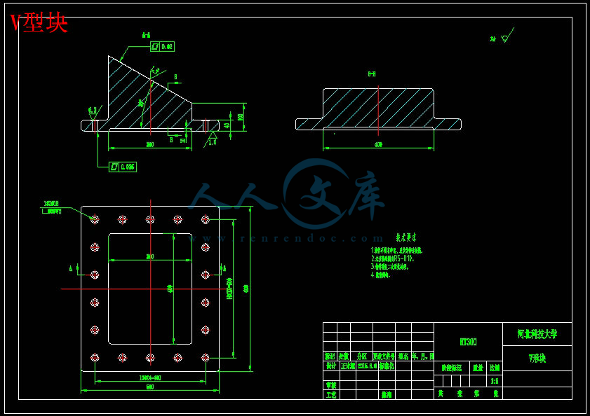
V型块.dwg
丝杠.dwg
丝杠螺母座.dwg
传动组件.dwg
减速器支架.dwg
套筒.dwg
导轨护罩.dwg
工件挡板.dwg
工作台.dwg
工作台装配.dwg
床身.dwg
总装图.dwg
护罩支架.dwg
护罩板.dwg
水平移动工作台.dwg
滑轮架.dwg
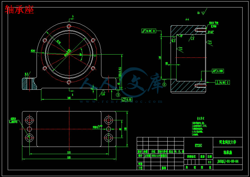
轴承座.dwg
轴承端盖.dwg
压缩包内文档预览:
预览图
编号:10600967    类型:共享资源    大小:12.51MB    格式:RAR    上传时间:2018-09-01 上传人:好资料QQ****51605 IP属地:江苏
50
积分
关 键 词:
龙门 铣床 水平 移动 挪动 工作台 大型 铸件 冒口 切割机 设计 三维 ug 全套 cad 图纸 以及 毕业 答辩 论文
资源描述:

【温馨提示】 购买原稿文件请充值后自助下载。

以下预览截图到的都有源文件,图纸是CAD,文档是WORD,下载后即可获得。


预览截图请勿抄袭,原稿文件完整清晰,无水印,可编辑。

有疑问可以咨询QQ:414951605或1304139763

随着机械制造行业的发展,大型铸件制造业所占地位有了显著提高。在国防、航天航空、船舶、交通运输等诸多领域起着很大作用。同时大型铸件浇冒口的切割问题在一定程度上制约了它的发展。目前国内大型铸件浇冒口的切割基本采用人工式切割,存在着劳动强度大、效率低等问题,在这种条件下提出了设计大型铸件浇冒口切割机床。

本文主要进行大型铝合金铸件浇冒口切割机床的工作台部分设计,本机床采用龙门框架式机床结构,工作台部分主要参考着龙门刨、铣床工作台进行设计。工作台主要工件承载部件-工作平台、水平导向部件-导轨、传动装置-滚珠丝杠副、动力源-电机、总体支承件-床身等几部分组成。本文主要进行了工作平台、床身底座的设计及导轨、传动装置-滚珠丝杠副、驱动装置-伺服电机及其他标准零部件的选型,并做了必要的校核,确保各个部件在强度和刚度上基本满足要求。

该机床工作台部件重约10吨,床身底座约20吨,总重约30吨。最大承载量15吨,行程3500mm,最大移动速度4000mm/s,最小移动速度40mm/s。


关键词  机床、工作台、传动


Title        Design of large aluminum castings poured             

                 riser cutting machine worktable                 


Abstract

With the development of the mechanical manufacturing industry,manufacturing accounts for a large casting status has improved significantly.In the defense, aerospace, shipbuilding, transportation, and many other areas plays a big role.At the same time large castings poured riser cutting problems to a certain extent, restrict the development of it.The current domestic large castings poured riser cutting basic using artificial cut,There is a large labor intensity and low efficiency.Under the condition of the proposed design of large castings poured riser cutting machine tools

This article mainly includes the large aluminum alloy castings poured riser cutting machine workbench,this machine adopts the gantry frame type machine tool structure, the workbench part main reference to design the planer, milling machine workbench.Workbench is mainly composed of artifacts bearing parts - work platform, the horizontal turning parts - guide rail, gear - ball screw pair, the power source - motor, the overall support - bed, etc. This paper was carried out the design of lathe bed base and the guide rail, actuator ball screw pair, drive servo motor and other standard parts selection, and do the necessary checking, ensure the parts on the strength and stiffness meet basically the requirements.

The machine table parts weighing about 10 tons, about 20 tons of lathe bed base, gross weight around 30 tons. Maximum capacity of 15 tons of stroke, 3500 mm, maximum speed 4000 mm/s, the minimum speed of 40 mm/s.


Key Words  Machine tool  workbench  drive


目   录


1 引言 1

1.1 课题背景及意义 1

1.2 国内外浇水口切割机的研究概况 1

2 本课题要解决的问题及其研究途径 4

2.1 任务分析 3

2.2 机床总体方案拟定 4

2.3 机床工作台整体布局 5

3 水平移动工作台设计 6

3.1 导轨 6

3.2 工作平台设计 10

3.3 传动设计 13

3.4 床身设计 26

4 夹具 33

4.1 夹具设计 33

4.2 确定固定夹具螺栓 34

结束语 36

致谢 37

参考文献 38


1 引言

1.1 课题背景及意义

熔融的金属液体流入预先做好的信模内,等到金属液凝固后将其取出,并除去浇冒口等,获得所需的铸件就是铸造。远在3500多年前人类就能能运用成熟的治炼技术来铸造出各种精美实用的铜器[1]。铸造是现代机械制造工业的基础,与此同时我国是铸造生产大国,可见铸造业在我国机械制造行业占据重要地位。其中大型铸件制造业是个特殊的行业,它的发展水平是衡量国家综合国力的重要标志,在我国的钢铁冶金、能源交通、石油化工、航空航天等多个领域的发展提供了大量的产品和服务,为我国现代化建设作出了重要贡献[2]。

将铸件从铸型中取出,清除掉本体以外的其他多余部分(主要指清除浇冒口),并将铸件内外表面打磨精整的过程成为铸件清理[3]。本文主要涉及的是大型铝合金铸件浇水口的切割系统,目前至今国内大型铸件浇冒口清除仍然采用手动切割机或半自动式切割机,操作工人穿着防护服、戴面具、隔热手套等装备手持工件进行切割,切割过程没有除尘装置,车间内灰尘杂质相当多,车间工作环境十分恶劣,污染十分严重[4]。国外一些发达国家大型铸件浇冒口清除已开始采用自动式切割机但进口设备价格昂贵,维护成本高。至此研发我国的大型铸件浇水口切割打磨机床已势在必行,对提高劳动生产力降低工人劳动强度意义重大。


内容简介:
Computer-AidedDesign42(2010)10851094 ContentslistsavailableatScienceDirect Computer-AidedDesign journalhomepage:/locate/cad Computeraidedfixturedesign:Recentresearchandtrends HuiWang a, ,Yiming(Kevin)Rong a,b ,HuaLi b ,PriceShaun b a DepartmentofPrecisionInstrumentsandMechanology,TsinghuaUniversity,Beijing,100084,China b ComputerAidedManufacturingLaboratory,WorcesterPolytechnicInstitute,MA,01609,USA a r t i c l e i n f o Articlehistory: Received7April2009 Accepted15July2010 Keywords: Computeraidedfixturedesign Literaturesurvey Trend a b s t r a c t Widelyusedinmanufacturing,fixtureshaveadirectimpactuponproductmanufacturingquality,pro- ductivityandcost,somuchattentionhasalreadybeenpaidtotheresearchofcomputeraidedfixture design(CAFD)andmanyachievementsinthisfieldhavebeenreported. Inthispaper,aliteraturesurveyofcomputeraidedfixturedesignandautomationoverthepastdecade isproposed.First,anintroductionisgivenonthefixtureapplicationsinindustry.Then,significantworks doneintheCAFDfield,includingtheirapproaches,requirementsandworkingprinciplesarediscussed. Finally,someprospectiveresearchtrendsarealsodiscussed. 2010ElsevierLtd.Allrightsreserved. 1. Introduction Afixtureisamechanismusedinmanufacturingtoholdawork- piece,positionitcorrectlywithrespecttoamachinetool,andsup- portitduringmachining.Widelyusedinmanufacturing,fixtures haveadirectimpactuponproductquality,productivityandcost. Generally,thecostsassociatedwithfixturedesignandmanufac- turecanaccountfor10%20%ofthetotalcostofamanufactur- ingsystem1.Approximately40%ofrejectedpartsaredueto dimensioningerrorsthatareattributedtopoorfixturingdesign2. Fixturedesignworkisalsotediousandtime-consuming.Itoften heavilyreliesonfixturedesignengineersexperience/knowledge andusuallyrequiresover10yearsmanufacturingpracticetode- signqualityfixtures3.Traditionally,thedesignandmanufacture ofafixturecantakeseveraldaysorevenlongertocompletewhen humanexperienceinfixturedesignisutilized.Andagoodfixture designisoftenbasedonthedesignersexperience,hisunderstand- ingoftheproducts,andatry-and-errorprocess. Therefore, with the increasingly intense global competition whichpusheseverymanufacturerinindustrytomakethebest efforttosharpenitscompetitivenessbyenhancingtheproducts quality,squeezingtheproductioncostsandreducingtheleadtime tobringnewproductstothemarket,thereisanstrongdesire fortheupgradingoffixturedesignmethodologywiththehope ofmakingsoundfixturedesignmoreefficientlyandatalower cost.Thedevelopmentofcomputer-aidedfixturedesign(CAFD) technologyoverthepastdecadescanbeattributedtothefulfilling ofthisgoal. Correspondingauthor. E-mailaddress:wanghuisx(H.Wang). Asanimportantfieldinmanufacturing,researchandapplica- tionsoffixturedesignhasbeenpaidmuchattentionoverpast decades4,5.Manyacademicandapplicationspapershavebeen publishedinthisarea.Inthispaper,wewillfocusonaninvestiga- tionofcomputeraidedfixturedesignresearchinthepastdecade. Thefollowingsectionswillgiveasurveyonthestateoftheartof theseresearches.Someconclusionsonresearchtrendsarealsodis- cussed. 2. Fixturesinmanufacturing Afixtureisdesignedtopositionandholdoneormorework- piece(s) within some specifications. It is widely used in man- ufacturing,e.g.machining(includingturning,milling,grinding, drilling,etc),welding,assembly,inspectionandtesting.Thefol- lowingFigs.19,aresomerealfixturedesigncasesinmanufactur- ing.Fixturescanbeclassifiedwithdifferentprinciples.However, comparedwiththepublicationsofCAFDresearchinmachiningfix- turefield,onlyafew616havebeenfocusedonotherimportant manufacturingfields,forinstance,assemblyfixturesandwelding fixtures. 2.1.Weldingfixtures Weldingisessentialtoahighdollarvolumeofmanufactur- ingprocesses,includingnationaldefenseindustries.Accordingto EconomicImpactandProductivityofWelding,HeavyManufacturing IndustriesReport,byAmericanWeldingSocietyandEdisonWeld- ingInstituteonJune2001,ThecontributionofweldingtotheUS economyin1999viatheseindustrieswasnolessthan$7.85bil- lion.Thisfigurerepresented7%oftotalexpendituresbythesefirms in199917,18.Sotherearesignificanttechnicalandcommercial 0010-4485/$seefrontmatter 2010ElsevierLtd.Allrightsreserved. doi:10.1016/j.cad.2010.07.0031086 H.Wangetal./Computer-AidedDesign42(2010)10851094 Fig.1. Machiningfixtures(IMAOcorp.)19. Fig.2. Machiningfixturesofaircraft-usedbearinghousing. Fig.3. Grindfixtureforturbineblades(aerocaddesign,inc.)20. advantagesinthedevelopmentanddeploymentofweldingfixture designsystems. Thereareobviousdifferencesbetweenmachiningfixturede- signandweldingfixturedesign.Asinthefollowing: Fig. 5. Automotive stud weld fixtures on a trunion frame, (DBM innovation inc.)22. Theworkpieceinaweldingprocessisusuallyanassemblyof severalparts,whileworkpiecesundergoingamachiningpro- cesscontainonlyonepart. Usually,theaccuracyrequirementinaweldingprocessisless thaninmachining. Fixingforcesandmachiningforcesinaweldingprocesscom- monlyaresmallerthaninmachining. Thermalreactionsinweldingshouldbeseriouslyconsidered. Furthermore,thesefactorsalsoshouldbepaidsomeattentionin weldingfixturedesigncases: Electricalconductivityiscriticalforarcweldingstability. Inadditiontothermalconductivity,whenselectingfixturema- terialthermalexpansionpropertiesalsoshouldbeconsidered. Refinedweldingwaveformsrequireanoptimizedweldingcir- cuittomaintainshortarclengthswhilereducingspatter,stub- bing,arcflare,andarcoutagestomaximizetravelspeeds. Morecomplexapplicationsmayrequireadedicatedfixture. Thedesignandinstallationofadedicatedfixturefrequentlyin- volvesinstallingandroutingwiringandpneumaticorhydraulic lines. Inthepastdecade,onlyverylimitedCAFDresearchandappli- cationshavebeenreportedintheweldingsector.Inthisfield,due totheimportanceofweldingforsheetmetalassemblyinautomo- bileandaerospaceindustries,theassemblyandweldingofsheet metalhasreceivedsomespecialattention.Aweldfixtureisof- tendevelopedtoreducethedeformationofeachworkpiecedue toheatandresidualstressintheweldingprocessand,hence,to reducethedimensionalvariationoftheassembly.Therefore,some methodsofofflineoronlinedeformationanalysisweredeveloped toenhancethefixturesabilityondeformationcontrolling8,9.In Fig.4. Assemblyfixturetolocateshelvesforassemblyofcabinets(pioneerindustrialsystemsLLC.)21.H.Wangetal./Computer-AidedDesign42(2010)10851094 1087 Fig.6. Robotweldfixture(IMPROVEsolutionsLLC.)23. ab Fig.7. Pin-arrayfixtureapplication29. Fig.8. Modularfixtureforapartfortheconstructionmachinery(BLUCOcorp.)30. Fig. 9. Dedicated fixture for a part for the construction machinery (BLUCO corp.)30. sheetmetalassemblywithlaserweldingfixturesalsoshoulden- sureafit-upofthematingsurfacestoensureproperlaserbeam weldoperationandlaserweldquality.Asaresult,atraditional 3-2-1locatingschemeisextendedtoamixedlocatingidea,total locatinganddirectlocatingforwelds1013.Thetotallocating schemeisusedtolocatetheentireassembly,andthedirectlocat- ingschemeisusedtolocatetheweldjointstomeetthemetals fit-uprequirement. 2.2.Applicationsofmodularfixturesanddedicatedfixtures Accordingtothefixturesflexibility,fixturesalsocanbeclas- sified as dedicated fixtures and general purpose fixtures (e.g. reconfigurableandconformablefixtures,modularfixtures).Recon- figurableandconformablefixtures2426canbeconfiguredto acceptpartsofvaryingshapesandsizes.Particularly,conformable pin-arrayfixturetechnology27iswidelyusedinmanyfixturede- signsbecausesomecomponentscontaininternalvariablesthatcan beadjustedtomeetthedifferentfeaturesofworkpieces(asFig.7). Andphase-changematerials-relatedfixturesalsoareusedinsome precisionmanufacturing.Forinstance,intheaerospaceindustry, lowmelting-pointmetalsareusedtoencloseturbinebladesand producewell-definedsurfacesforpartlocationandclampingfor grindingoperations. Themostimportantandwidestusedwithinthegeneralpur- posefixtureclassificationsaremodularfixtures.Astheflexible manufacturingsystemhasbeenadoptedbymoreandmoreman- ufacturerswhoaretryingtoremaincompetitiveinthisrapidly changingmarketbyrunningproductionwithshortleadtimesand wellcontrolledcost,modularfixtureshavegainedinpopularitybe- causeofitsperformanceoneasyusage,versatility,anditsadapt- abilitytoproductchanges.1088 H.Wangetal./Computer-AidedDesign42(2010)10851094 Fig.10. Adedicatedtubebendingfixture(Wintonmachinecompany)31. Modularfixturesallowawiderflexibilitybymakinguseofstan- dardworkholdingdevicesandcomponents.Theirflexibilityisde- rivedfromthelargenumberofpossiblefixtureconfigurationsfrom thedifferentcombinationsoffixturecomponents.Theapplication ofmodularfixturescontributesconsiderablytoshorteningthelead timeandreducingthecostinsmall-volumeproductionwithver- satileproducts.However,italsohassomelimitations28: Onlylimitedcombinationscanbeachievedfromthesecompo- nents,meaningthatitispossiblethatnosuitablecombination canbebuiltforsomeworkpieceswithirregularorcomplexge- ometries. Structuralpropertiesofmodularfixturesaresometimesdiffi- culttobemaintained.Structuralpropertiesofmodularfixtures includelocatingaccuracy,stiffness,stability,loadingandun- loading,operatingspeed,etc.Itiscommonthatusingmodular fixturesmaynotachieveanoptimalfixturingquality. Notsuitableformassproduction,e.g.automotiveproduction anditscomponentsmanufacture. Forcomparisonssake,Fig.8showsamodularfixtureusedfor apartfortheconstructionmachinery,andthesamepartalsoused inFig.9,whereadedicatedfixturesolutionisgiven. Thededicatedfixturesarealsoimportantinmanufacturing, particularly,foradvanced,sophisticatedandprecisepartormass production.Becauseadedicatedfixtureisdesignedforaspecific product,thedesignercancarefullytailorthedesigntonotonly meetthebasicfixturingrequirementssuchasthelocatingac- curacy,stability,stiffness,butalsooptimallyfacilitatetheoper- ationalrequirementssuchasloading/unloadingconvenienceand efficiency,andeffectivechipdisposaletc.AndFig.10isadedicated tubebendingfixture. Comparedwithmodularfixtures,dedicatedfixturesarede- signedcarefullyaccordingtoworkpiecesdesignandmanufac- turingrequirements.Sotherearemoreuncertaintiesimposedon dedicatedfixturedesigntasks.Inmodularfixturedesign,thereisa componentlibrarywithpre-designedanddimensionedstandard- izedfixturecomponents.Thus,themodularfixtureconfiguration designisactuallytoassemblethefixturecomponentsintoacon- figuration. Duetoitsextensiveuseincurrentmanufacturingandstan- dardizedproduction,inmanyreportedCAFDresearchesandap- plications,modularfixturingprinciplesareemployedtogenerate fixturedesigns3243.EarlyCAFDinmodularfixturesmerely usedthedraftingcapabilitiesofaCADsysteminassembly.Modular fixtureelementssuchasbaseplates,locators,supportsandclamps arestoredinadatabase.Basedonthefixturingidea,first,thede- signerspecifiestheprimarylocatingsurface(point)anditslocator positions,thesuitableclampingsurfacesandpositions,andthen selectsandplacestheappropriatefixturingcomponentsinthede- siredpositions.Althoughthereisareductioninthetotaltimetaken Fig.11. Thebasicelementsofthefixturedesignprocess. toproduceafixtureassembly,thefinaldesigndependslargelyon thedesignersexperience.Thustheyonlyprovidefixtureengineers withasimpletooltodofixturedesignmanuallybasedonsomeex- tendedfunctionsofcommercialCADsoftware.Asaresult,current industrialapplicationsofCAFDareverylimitedeventhoughthere aremanyreportedresearchachievements. Overthepastdecade,muchfocushasbeenputonintelligent methodsforcomputeraidedfixturedesigntoseekatechnical breakthroughinembeddingmoredesignknowledgeintosemi- automaticorautomaticCAFDsystems.Adetaileddiscussionwill bedoneinthefollowingsections(Table1). 3. Stateoftheart 3.1.Intelligentandautomaticfixturedesignmethods Typically,fixturedesigninvolvestheidentificationofclamps, locators,andsupportpoints,andtheselectionofthecorresponding fixtureelementsfortheirrespectivefunctions.Therearefourmain stageswithinafixturedesignprocesssetupplanning(D 1 ),fixture planning(D 2 ),fixtureunitdesign(D 3 )andverification(D 4 ),as Fig.11illustrates48,63.Setupplanningdeterminesthenumber ofsetupsrequiredtoperformallthemanufacturingprocesses, thetaskforeachsetup,e.g.,theongoingmanufacturingprocess andworkpiece,orientationandpositionoftheworkpieceineach setup.Asetuprepresentsthecombinationofprocessesthatcan beperformedontheworkpiecebyasinglemachinetoolwithout havingtochangethepositionandorientationoftheworkpiece manually.Duringfixtureplanning,thesurfaces,uponwhichthe locatorsandclampsmustact,aswellastheactualpositionsof thelocatingandclampingpointsontheworkpiece,areidentified. Thenumberandpositionoflocatingpointsmustbesuchthat theworkpieceisadequatelyconstrainedduringthemanufacturing process.Inthethirdstageoffixturedesign,suitableunits,(i.e.,the locatingandclampingunits,togetherwiththebaseplate),are generated.Duringtheverificationstage,thedesignistestedto ensurethatallmanufacturingrequirementsoftheworkpiececan besatisfied.Thedesignalsohastobeverifiedtoensurethatit meetsotherdesignconsiderationsthatmayincludefixturecost, fixtureweight,assemblytime,andloading/unloadingtimeofboth theworkpieceandfixtureunits50. Currently,eventhoughnumeroustechniquesconcentratingon fixturedesignhavebeenproposedandmadesomeachievements,H.Wangetal./Computer-AidedDesign42(2010)10851094 1089 Table1 CurrentCAFDliterature. Method Levelofdetail Application D 1 D 2 D 3 D 4 Shen,etal.6 Reconfigurablefixtures,Automotiveengine machiningandassembly Liu,etal.7 Assemblyfixturefaultdiagnosis,sheetmetal joiningprocess Lienetal.8 Integratedmeasurementinclamping systems On-linecorrectionofweldingpaths,Robotic weldingofthin-walledaluminumstructures Sikstrom,etal.9 Superelement(SE)fixturemodeling, Coupledthermalmechanicalanalysis Fixturedesigninfusionwelding Zheng,etal.32 Precisemodularfixture Peng,etal.3335 Desktopvirtualrealitytechnology Modularfixturedesignandsimulation Kumar,etal.36 CAD-basedcollisiondetection Modularfixtures Mervyn,etal.38 Evolutionarysearchalgorithm IMAOmodularfixtures Subramaniam,etal.44,45 Multi-agentsystem,Genetic algorithmsandNeuralnetworks Fan,etal.46,47 XMLbasedinformation representation,Casebasedreasoning method Wua,etal.37 Linkagemechanismtheory:afour-bar mechanismandlinkagecurve Modularfixture Hou,etal.39 Modularfixtures Girish,etal.40 Tabusearch Fixtureelementsmanagement Modularfixtureelements Lin,etal.41 Modularfixturesformeasurement Kakish,etal.42 Knowledge-basedmodeling Universalmodularjigsand fixturesinformationmodeling Universalmodularjigsandfixtures Cai,etal.43 TRIZevolutiontechnology TRIZ-basedevolutionstudyformodularfixture Boyle,etal.48,49 Casebasedreasoning Wang,etal.50 Casebasedreasoning Modularfixturesforwelding Chen,etal.51 Casebasedreasoning Wardak,etal.52,53 Finiteelementmethod Drillingfixtures Krishnakumar,etal.54,55 Finiteelementmethod,Genetic algorithm Machiningfixtures Subramanian,etal.56,57 Geneticalgorithm Hamedi58 Artificialneuralnetwork,Genetic algorithm,Finiteelementmethod Choubey,etal.59 Geneticalgorithm Machiningfixtures Kaya60 Finiteelementmethod,Genetic algorithm Machiningfixture Aoyama,etal.61 Geneticalgorithm Li,etal.1013 Finiteelementmethod,Genetic algorithm Sheetmetalassemblywithlaserwelding Ding,etal.14,15 Fixturefaultdiagnosis,assemblyprocesses Kang,etal.6265 Amaral,etal.66 Finiteelementanalysis Zheng,etal.6769 Finiteelementanalysis Forfixturestiffness, Hurtado,etal.7072 Finiteelementmethod,modelingof fixture-workpiececontacts Machiningfixtures Ratchev,etal.73 Finiteelementmethod Thepredictionofpart-fixturedeformationand tolerance Asante74 Finiteelement-based Loadandpressuredistributioncalculation Wang7579 Toleranceanalysisinfixture-workpiecesystem Estrems,etal.80 Fixturesinmachiningprocesses Bansal,etal.81 Anintegratedfixtureplanningsystemfor minimumtolerances Li,etal.16 MultiobjectiveOptimization Toleranceallocation,assemblyfixture Wu28 Geometrygenerationoffixture Note:Setupplanning(D1),fixtureplanning(D2),fixtureunitdesign(D3)andverification(D4). matureandcommercialCAFDapplicationsalsoareverylimited. Fixture design still continues to be a major bottleneck in the promotion of current manufacturing. This work currently, is implementedbyatypicaldesigner-centeredpattern,thatis,all fixturedesignrelatedworkisheavilydependantontheexperience andknowledgeoffixturedesigner.Thissituationhampersthe improvementofproductivity,requiresalongtimetocultivate anexperiencedfixturedesignerandmakethefixturedesignjob weakwithamajorbottleneck.Thus,newintelligentorautomatic technologiesonsynthesizingtraditionalgeometricdesigntools, designknowledge,andpastdesigncaseshaveattractedmuch interestinbothacademicinstitutionsandindustries.Theefforts overpastdecadesinthisfieldhaveresultedinnumerouscomputer aidedfixturedesign(CAFD)applicationsusingvariousintelligent methods,suchasexpertsystem,casebasedreasoning,andgenetic algorithm(GA),etc. Inessence,developingfixturedesignmethodologyneedsto cleartwocrucialproblems:howtorepresentfixturedesignknowl- edgeinacomputerandhowtoimplementtheproblemsolving procedure. AttheinitialstageofCAFDtwodecadesago,expertsystems wereoftenusedasaheuristictool,whichcanenlightenfixture designertoacompletefixturedesignsolution,particularly,fixture configurationdesigninaninteractiveenvironment82.Inmost of these methods, design knowledge is modeled as a set of manyIF-THENrules.Then,duringtheinteractivefixturedesign process,thedesignsolutionwouldbeconcludedbyaseriesof questioningansweringactionsbasedontheserules.However,1090 H.Wangetal./Computer-AidedDesign42(2010)10851094 Table2 SomeCBRmethodsinCAFD. Caserepresentation CBRprocedure Chen, etal.51 Definefixturedesignby attributestemplate Interactivemode:Designer selectssomeimportant attributestomatchcurrent designcasewithstoredcases Fan, etal.46,47 XMLandUML Boyle, etal.48,49 Dividefixturedesign informationintotwo libraries:conceptualdesign libraryandfixtureunit library Combinationofthesearch resultsfromtwocase libraries Sun, etal.83 UsingM
温馨提示:
1: 本站所有资源如无特殊说明,都需要本地电脑安装OFFICE2007和PDF阅读器。图纸软件为CAD,CAXA,PROE,UG,SolidWorks等.压缩文件请下载最新的WinRAR软件解压。
2: 本站的文档不包含任何第三方提供的附件图纸等,如果需要附件,请联系上传者。文件的所有权益归上传用户所有。
3.本站RAR压缩包中若带图纸,网页内容里面会有图纸预览,若没有图纸预览就没有图纸。
4. 未经权益所有人同意不得将文件中的内容挪作商业或盈利用途。
5. 人人文库网仅提供信息存储空间,仅对用户上传内容的表现方式做保护处理,对用户上传分享的文档内容本身不做任何修改或编辑,并不能对任何下载内容负责。
6. 下载文件中如有侵权或不适当内容,请与我们联系,我们立即纠正。
7. 本站不保证下载资源的准确性、安全性和完整性, 同时也不承担用户因使用这些下载资源对自己和他人造成任何形式的伤害或损失。
提示  人人文库网所有资源均是用户自行上传分享,仅供网友学习交流,未经上传用户书面授权,请勿作他用。
关于本文
本文标题:龙门铣床水平移动工作台-大型铝铸件浇冒口切割机工作台设计【三维UG】【全套18张CAD图纸和毕业答辩论文】
链接地址:https://www.renrendoc.com/p-10600967.html

官方联系方式

2:不支持迅雷下载,请使用浏览器下载   
3:不支持QQ浏览器下载,请用其他浏览器   
4:下载后的文档和图纸-无水印   
5:文档经过压缩,下载后原文更清晰   
关于我们 - 网站声明 - 网站地图 - 资源地图 - 友情链接 - 网站客服 - 联系我们

网站客服QQ:2881952447     

copyright@ 2020-2024  renrendoc.com 人人文库版权所有   联系电话:400-852-1180

备案号:蜀ICP备2022000484号-2       经营许可证: 川B2-20220663       公网安备川公网安备: 51019002004831号

本站为文档C2C交易模式,即用户上传的文档直接被用户下载,本站只是中间服务平台,本站所有文档下载所得的收益归上传人(含作者)所有。人人文库网仅提供信息存储空间,仅对用户上传内容的表现方式做保护处理,对上载内容本身不做任何修改或编辑。若文档所含内容侵犯了您的版权或隐私,请立即通知人人文库网,我们立即给予删除!