制钵机的设计说明书.doc

制钵机的设计【7张CAD图纸和说明书】

收藏

资源目录
跳过导航链接。
制钵机的设计【7张CAD图纸和说明书】.rar
制钵机的设计说明书.doc---(点击预览)
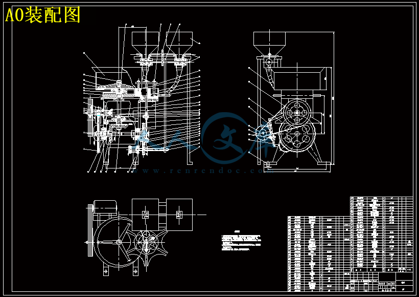
A0装配图.dwg
A1大带轮.dwg
A1大齿轮1.dwg
A1槽轮转盘.dwg
A2轴.dwg
A3-偏心轮.dwg
A3偏心轮.dwg
压缩包内文档预览:(预览前20页/共57页)
预览图 预览图 预览图 预览图 预览图 预览图 预览图 预览图 预览图 预览图 预览图 预览图 预览图 预览图 预览图 预览图 预览图 预览图 预览图 预览图
编号:18127350    类型:共享资源    大小:968.84KB    格式:RAR    上传时间:2019-04-25 上传人:俊****计 IP属地:江苏
40
积分
关 键 词:
7张CAD图纸和说明书 制钵机的设计【7张CAD图纸 制钵机的设计 张CAD图纸和说明书】 制钵机的设计【 CAD图纸设计 设计及CAD图纸
资源描述:

目录


摘  要 5

1、引言 5

1.1研究设计制钵机的意义 5

1.2制钵机现状分析 5

1.3制钵机的应用前景 5

1.4课题研究的内容及拟采取的技术、方法 5

2、制钵机的用途和设计要求 5

2.1用途 5

2.2设计要求 5

3、制钵机总体方案的设计 5

3.1工艺分析 5

3.2 机构的方案比较及选择 5

3.3拌料、填料 5

3.4物料输送和各工序转移 5

3.5钵体的成型和冲出 5

3.6播种和覆土 5

3.7协调配合关系 5

3.8拟定传动方案 5

4、绘制工作循环图 5

5、减速系统的设计 5

5.1电动机的选择 5

5.2传动比的确定,各轴功率以及带传动设计 5

5.3齿轮设计和校对 5

6、主要结构设计 5

6.1模盘的结构和尺寸确定 5

6.2曲柄(偏心轮)滑块(滑杆)机构的结构尺寸 5

6.3轴Ⅲ的结构设计及其校核 5

6.4轴承的校核 5

6.5键较核 5

6.6机构生产调节说明 5

7、总结 5

参考文献: 5

致谢 5


制钵机的设计

摘 要:本文所设计的ZBJ1000型制钵机是用来生产在农业生产中广泛使用的育秧钵。育秧钵的钵体由配有各种肥料的土壤做成圆柱状,上端有一凹孔,用来播种种子。用育秧钵进行育苗和移栽,能够保证种子有足够养料以及种子成苗后可以方便的移栽到田间,种子发芽率、成活率高,苗体强壮且防虫害。

    ZBJ1000型制钵机,吸取了前人研究成果的精华,与手工制钵和过去的制钵机不同的是,ZBJ1000型制钵机具有生产率更高,结构更简单,操作更方便,基本实现自动化,性价比高等优点;提高了生产效率并可实现大规模生产,可以保证秧苗早育、早熟、早上市,同时还能节约劳动力、种子、肥料、农药等。

    本文从ZBJ1000型制钵机的工作原理、运动协调、总体结构、运动和尺寸等多方面进行了说明和分析。


关键词:制钵机、育秧、运动分析、营养钵


Abstract:ZBJ1000 earthen bowl machine ,which is designed in this text ,is used to produce the seedling bowl ,which is very popular in the agricultural produce .The seedling bowl is made as a cylinder by the nutritional soil ,which consists of all kinds of fertilizer .And there is a cave pit in the top of the bowl , which is the very hole we put the seedling in .Growing and transplanting the seeds in this bowl can make sure the seeds have enough time and nutrition to grow with ,high germination rate ,high survival rate ,strong and anti-pest.

     ZBJ1000 earthen bowl machine ,differently from the former machine ,has lots of benefits just like :higher production ,easier structure ,more convenient handling ,automation and economy .Besides it can realize the earlier growth ,earlier maturity ,earlier on market , and it can economy labor force ,fertilizer and agrochemical at the same time.

     This text is going to introduce the ZBJ1000 earthen bowl machine about its structure ,motion ,work principle and size.


Keywords:earthen bowl machine 、nursery 、kinematical analysis 、bowl.

1、引言

1.1研究设计制钵机的意义

    育苗制钵机广泛应用于我国农业生产中,目前,建设社会主义新农村是我国的一项政策。在建设社会主义新农村的过程中,提高农业机械的生产效率,降低农业机械的成本是不容忽视的,从这个方面来说,本课题设计全自动制钵机是响应国家政策,是有利于农村发展的,具有长远的发展前景。

    选制钵机作为毕业设计的内容,一方面,可全面的总结大学四年来所学的专业知识,并将本专业各方面的知识的运用结合起来,锻炼了自己的机械综合运用专业素质;另一方面,初步尝试了从事系统的科学研究,通过本次设计,深入认识了一般成型机的设计方法和思路,对毕业以后的工作学习有很大的帮助。此外,制钵机的设计内容、工作量适合,作为毕业设计的内容是完全符合要求的。

1.2制钵机现状分析

    1.国内发展概况

我国对农作物机械化育苗移栽技术的研究早在20世纪50年代末至60年代初已经开始,但当时人们只看到育苗移栽的好处和效率,忽视了经济效益,更没有科学地分析育苗移栽机械化生产过程中的多种技术难题。近年来,人们对育苗移栽技术有了进一步认识,开始对其重视起来。然而,由于我国地域辽阔,自然条件千差万别,各地的生产条件和环境各不相同,加之各地经济发展水平不一致,所以到现在为止,总体上基本于一种小规模手工操作状态。

1.3制钵机的应用前景

机械化育苗的发展促进了种植制度的改革和进步机械化育苗技术的发展促使作物移栽种植面积增加,露地直播面积减少。种植者认为:购买商品苗直接定植,虽然较露地直播约增加成本20%左右,但是可实现管理规范化,而且种植密度有保障,节省劳力,能增产20%,作物生长整齐一致,便于机械化作业和采收。

2、制钵机的用途和设计要求

2.1用途

营养土钵制钵机是一种制作培育苗钵体土胚的机器,该机可替代人工自动制作钵体,具有生产效率高,结构简单,稳固可靠,容易操作等特点。

育苗钵是一种培农作物育苗用的土胚,它能使种子在育苗期有足够的养料及苗成长后能方便的移植到田间栽种。育苗钵由配有各种肥料的土壤做成圆柱形状并在上端挖一个凹孔使之成钵状。使用时将种子播在凹孔中,用土覆盖,待苗成长后连育苗钵一起移到田间栽种即可。

内容简介:
毕业设计说明书题 目: 制钵机的设计 学 院: 专 业: 学 号: 姓 名: 指导教师: 完成日期: 毕业论文(设计)任务书论文(设计)题目: 制钵机的设计 学号: 姓名: 专业: 指导教师: 系主任: 一、主要内容及基本要求 (1)机械式全自动制钵机用于加工水稻、小麦、豆类作物育苗用的营养土钵(营养土压成块,内抱种子)。营养土播规格为6080mm,播种量为35粒/穴,生产率为1880穴/小时。 (2)分析制钵机工作原理和技术要求及构思方案(含方案比较)。 (3)完成制钵机传动系统的设计、机构设计和结构设计。主要零部件的受力分析和强度计算。绘制所设计方案的机构运动简图;绘制制钵机的装配图及主要的零件图。要求图纸工作量2.5张A0图纸以上(AutoCAD绘图)。 (4)设计说明书一份,电子文档一份。 (5)英文文献翻译(含原文)。要求:原文3000个单词以上,中文翻译要求通顺。 二、重点研究的问题(1)制钵机总体方案设计(含制钵压钵、排种、钵盘转动、送钵、推钵机构等)。 (2)制钵机传动系统的设计。 (3)主执行机构设计(机构选型)及其结构设计。 三、进度安排 各阶段完成的内容起止时间1收集资料、查询相关文献2012年1月8日2月20日2掌握制钵机工作原理和技术要求,进行方案构思与设计2012年2月21日 3月8日3完成传动系统及机构设计和主要零件设计计算2012年3月9日 3月31日4绘制装配图和零件图草图2012年4月1日5月2日5完成装配图和零件图的设计2012年5月3日5月15日6撰写毕业设计说明书及英文文献翻译2012年5月16日 5月26日7交毕业设计说明书,准备答辩2012年5月 27 日 5月28日四、应收集的资料及主要参考文献主要的收集资料有:机械设计手册、干粉压片机相关文献 1张晓玲主编.机械原理课程设计指导.北京航空航天大学出版社,2008. 2孟宪源,姜琪主编.机构构型与应用.机械工业出版社,2004 . 3侯珍秀主编.机械系统设计.哈尔滨工业大学出版社,2000 . 4黄继昌、徐巧鱼等编.实用机械机构图册.人民邮电出版社,1996. 5 张维凯,王曙光. AutoCAD2007中文版标准教程北京:清华大学出版社,2007. 6 濮良贵,纪名刚.机械设计(第八版).北京:高等教育出版社,2007. 7 孙恒,陈作模.机械原理(第七版)。北京:高等教育出版社,2006. 8 成大先主编.机械设计手册.北京:化学工业出版社,2004. 毕业论文(设计)评阅表学号 姓名 专业 毕业论文(设计)题目: 制钵机的设计 评价项目评 价 内 容选题1.是否符合培养目标,体现学科、专业特点和教学计划的基本要求,达到综合训练的目的;2.难度、份量是否适当;3.是否与生产、科研、社会等实际相结合。能力1.是否有查阅文献、综合归纳资料的能力;2.是否有综合运用知识的能力;3.是否具备研究方案的设计能力、研究方法和手段的运用能力;4.是否具备一定的外文与计算机应用能力;5.工科是否有经济分析能力。论文(设计)质量1.立论是否正确,论述是否充分,结构是否严谨合理;实验是否正确,设计、计算、分析处理是否科学;技术用语是否准确,符号是否统一,图表图纸是否完备、整洁、正确,引文是否规范;2.文字是否通顺,有无观点提炼,综合概括能力如何;3.有无理论价值或实际应用价值,有无创新之处。综合评 价该设计符合专业培养目标,能够达到综合训练目标,题目有一定难度,工作量大。选题具有一定的研究意义。该生查阅资料能力强,能够全面收集关于制钵机的资料。具备了一定的专业理论的综合运用能力,设计过程中能够综合运用所学知识分析问题和解决问题,能够很好地运用AUTO-CAD绘图软件绘制装配图和零件图,所绘制的装配图与零件图错误较少,基本达到工程图的要求。说明书内容完整,格式正确。整个毕业设计工作体现了学科教学计划的基本要求,所完成的工作达到了本科毕业设计要求。评阅人: 2014年5月 日 毕业论文(设计)鉴定意见学号: 姓名 专业: 毕业论文(设计说明书) 45 页 图 表 6 张论文(设计)题目: 制钵机的设计 内容提要:本论文所研究设计的育苗制钵机广泛应用于农业生产中,营养土钵制钵机是一种制作培育苗钵体土胚的机器,该机可替代人工自动制作钵体,具有生产效率高,结构简单,稳固可靠,容易操作等特点。育苗钵是一种培农作物育苗用的土胚,它能使种子在育苗期有足够的养料及苗成长后能方便的移植到田间栽种。育苗钵由配有各种肥料的土壤做成圆柱形状并在上端挖一个凹孔使之成钵状。使用时将种子播在凹孔中,用土覆盖,待苗成长后连育苗钵一起移到田间栽种即可。制造钵体需要五个工艺流程,即填料冲压成型播种覆土冲出成品进入下一个循环。本论文从制钵机的工作原理、运动协调性、总体结构以及各执行机构的运动和尺寸进行了分析和说明。指导教师评语该同学对待毕业设计任务认真负责,积极查阅资料,认真思考解决问题的方法,并能主动和老师积极探讨。具备综合运用知识去确定设计方案,独立解决设计中问题的能力。所设计的制钵机的设计原理正确,控制方法得当。所绘制图纸基本达到工程图的水平,所完成的毕业设计说明书条理清楚、计算正确,文字基本流畅。整个毕业设计工作量达到要求,完成质量较高,达到学士学位论文要求。同意参加答辩,推荐毕业设计成绩等级为“中等”。 指导教师: 年 月 答辩简要情况及评语答辩小组组长: 年 月 日答辩委员会意见 答辩委员会主任: 年 月 日目录摘要51、引言51.1研究设计制钵机的意义51.2制钵机现状分析51.3制钵机的应用前景51.4课题研究的内容及拟采取的技术、方法52、制钵机的用途和设计要求52.1用途52.2设计要求53、制钵机总体方案的设计53.1工艺分析53.2 机构的方案比较及选择53.3拌料、填料53.4物料输送和各工序转移53.5钵体的成型和冲出53.6播种和覆土53.7协调配合关系53.8拟定传动方案54、绘制工作循环图55、减速系统的设计55.1电动机的选择55.2传动比的确定,各轴功率以及带传动设计55.3齿轮设计和校对56、主要结构设计56.1模盘的结构和尺寸确定56.2曲柄(偏心轮)滑块(滑杆)机构的结构尺寸56.3轴的结构设计及其校核56.4轴承的校核56.5键较核56.6机构生产调节说明57、总结5参考文献:5致谢5制钵机的设计摘要:本文所设计的ZBJ1000型制钵机是用来生产在农业生产中广泛使用的育秧钵。育秧钵的钵体由配有各种肥料的土壤做成圆柱状,上端有一凹孔,用来播种种子。用育秧钵进行育苗和移栽,能够保证种子有足够养料以及种子成苗后可以方便的移栽到田间,种子发芽率、成活率高,苗体强壮且防虫害。 ZBJ1000型制钵机,吸取了前人研究成果的精华,与手工制钵和过去的制钵机不同的是,ZBJ1000型制钵机具有生产率更高,结构更简单,操作更方便,基本实现自动化,性价比高等优点;提高了生产效率并可实现大规模生产,可以保证秧苗早育、早熟、早上市,同时还能节约劳动力、种子、肥料、农药等。 本文从ZBJ1000型制钵机的工作原理、运动协调、总体结构、运动和尺寸等多方面进行了说明和分析。关键词:制钵机、育秧、运动分析、营养钵Abstract:ZBJ1000 earthen bowl machine ,which is designed in this text ,is used to produce the seedling bowl ,which is very popular in the agricultural produce .The seedling bowl is made as a cylinder by the nutritional soil ,which consists of all kinds of fertilizer .And there is a cave pit in the top of the bowl , which is the very hole we put the seedling in .Growing and transplanting the seeds in this bowl can make sure the seeds have enough time and nutrition to grow with ,high germination rate ,high survival rate ,strong and anti-pest. ZBJ1000 earthen bowl machine ,differently from the former machine ,has lots of benefits just like :higher production ,easier structure ,more convenient handling ,automation and economy .Besides it can realize the earlier growth ,earlier maturity ,earlier on market , and it can economy labor force ,fertilizer and agrochemical at the same time. This text is going to introduce the ZBJ1000 earthen bowl machine about its structure ,motion ,work principle and size.Keywords:earthen bowl machine 、nursery 、kinematical analysis 、bowl.1、引言1.1研究设计制钵机的意义 育苗制钵机广泛应用于我国农业生产中,目前,建设社会主义新农村是我国的一项政策。在建设社会主义新农村的过程中,提高农业机械的生产效率,降低农业机械的成本是不容忽视的,从这个方面来说,本课题设计全自动制钵机是响应国家政策,是有利于农村发展的,具有长远的发展前景。 选制钵机作为毕业设计的内容,一方面,可全面的总结大学四年来所学的专业知识,并将本专业各方面的知识的运用结合起来,锻炼了自己的机械综合运用专业素质;另一方面,初步尝试了从事系统的科学研究,通过本次设计,深入认识了一般成型机的设计方法和思路,对毕业以后的工作学习有很大的帮助。此外,制钵机的设计内容、工作量适合,作为毕业设计的内容是完全符合要求的。1.2制钵机现状分析 1.国内发展概况我国对农作物机械化育苗移栽技术的研究早在20世纪50年代末至60年代初已经开始,但当时人们只看到育苗移栽的好处和效率,忽视了经济效益,更没有科学地分析育苗移栽机械化生产过程中的多种技术难题。近年来,人们对育苗移栽技术有了进一步认识,开始对其重视起来。然而,由于我国地域辽阔,自然条件千差万别,各地的生产条件和环境各不相同,加之各地经济发展水平不一致,所以到现在为止,总体上基本于一种小规模手工操作状态。1.3制钵机的应用前景机械化育苗的发展促进了种植制度的改革和进步机械化育苗技术的发展促使作物移栽种植面积增加,露地直播面积减少。种植者认为:购买商品苗直接定植,虽然较露地直播约增加成本20%左右,但是可实现管理规范化,而且种植密度有保障,节省劳力,能增产20%,作物生长整齐一致,便于机械化作业和采收。2、制钵机的用途和设计要求2.1用途营养土钵制钵机是一种制作培育苗钵体土胚的机器,该机可替代人工自动制作钵体,具有生产效率高,结构简单,稳固可靠,容易操作等特点。育苗钵是一种培农作物育苗用的土胚,它能使种子在育苗期有足够的养料及苗成长后能方便的移植到田间栽种。育苗钵由配有各种肥料的土壤做成圆柱形状并在上端挖一个凹孔使之成钵状。使用时将种子播在凹孔中,用土覆盖,待苗成长后连育苗钵一起移到田间栽种即可。2.2设计要求1.钵的结构尺寸(见图2.1) 图2.1 营养土钵 本设计具体参数有如下几点要求:1、 生产率;2、 设工作年限10年,每年工作300天,每天工作8小时。3、 营养土钵规格2025mm,播种量为。3、制钵机总体方案的设计3.1 工艺分析3.1.1最早的手工制秧钵的方法步骤:(1)将肥料和土壤拌均匀,用筛子筛细。 (2)将上述土壤放入一个模子,见图3.1 a 。 (3)用一冲头将土壤冲紧,冲头下部有一凸头,见图3.1 b 。 (4)再将模子托起,育苗钵被冲出,见图3.1 c 。a) b) c)图3.1 手工制作营养土钵由手工制造方法可知,制造钵体需要五个工艺流程,即填料冲压成型播种覆土冲出成品进入下一个循环 图3.23.2 机构的方案比较及选择3.2.1制钵压钵、送钵执行机构的方案比较方案一:曲柄(偏心轮)滑块(滑杆)机构(如图3.3所示)图3.3 图3.3偏心轮的匀速转动,推动滑块上下滑动,滑块带动压杆推杆上、下移动实现对模盘孔内土进行冲压成钵。优点:偏心轮适合较高的转速,在曲柄转动下,带动压杆往复运动,并且采用对心结构,能使压杆推杆运动平稳,而且能够承受较大的载荷,机械效率较高。缺点:传动路线较长。方案二:凸轮机构(如图3.4所示)图3.4 图3.4凸轮机构匀速转动,推动推杆上下移动,压杆推杆对营养土钵冲压成型。优点:通过设计不同的轮廓曲线,可以实现预期的各种运动规律,并能有效冲击,只要恰当设计好轮廓曲线,能使压力大小随运动而变化并且凸轮机构响应快速,机构紧凑。缺点:凸轮不适合较快速的运转,很容易磨损。方案三:曲柄滑块机构(如图3.5所示)图3.5 图3.5曲柄匀速转动,推动滑块上下移动,滑块带动压杆推杆上下移动实现对营养土的冲压。此方案与方案一、二比较,区别在于驱动构件的不同,在大麻烦是动力部分,无法提供足够的动力带动驱动件转动。综上三种方案所述,由于要求机构运动速度较快,传动平稳,机械效率高,机械使用寿命长,综合考虑选择方案一。 3.2.2排种机构的设计与分析 方案一、槽轮机构(如图3.6所示)图3.6 图3.6拨盘匀速转动,拨盘上的圆销进入槽轮径向槽时,推动槽轮转动,从而实现排种,圆销未进入槽轮,槽轮不动,不排种,槽轮间歇性运动实现定时定地的排种。优点:机构简单,外形尺寸小,机械效率搞,并能较平稳的间歇性转动,适用于速度不太高的场合。缺点:存在柔性冲击,使构件损坏,而且槽轮机构制造工艺复杂。方案二:几轮机构(如图3.7所示)图3.7 图3.7当摇杆逆时针转动时,棘爪推动棘轮顺时针转动一个角度,止动爪阻止棘轮转动,棘轮静止不动,摇杆往复摆动以拨动棘轮间歇转动,棘轮没转动一格,就往下排种,摇杆顺时针转动不排种。优点:机构简单,制造方便,运动可靠。缺点:工作时有较大的冲击和噪声,运动槽度较差,不适合高速转动和重载荷场合。方案三:不完全齿轮机构(如图3.8所示)图3.8 图3.8完全齿轮转动一圈,推动从动轮转动一格,从而使种子下落到钵孔内,在不啮合时,种子则不会下落。优点:结构简单,容易制造,工作可靠,制造成本低。缺点:受到冲击较大,不适合高速的运动场合,齿数较少,会产生根切,对齿轮造成破坏,传动平稳性较差。综上三种方案,考虑到传动平稳性,及更好地满足设计要求,选择方案一合适。3.2.3钵盘转动机构的设计与分析方案一、槽轮机构(如图3.6所示)主动拨盘带动圆销转动,圆销进入槽轮时,驱动槽轮转动,带动钵盘转动,圆销未进入槽轮时,槽轮被卡住,钵盘不转动,从而实现了钵盘每转过60的间歇运动。优点:槽轮机构简单,外形尺寸小,机械效率高,并能够平稳地间歇性转位。方案二、棘轮机构(如图3.7所示)摇杆往复摆动,使棘轮间歇性转动,棘轮每转动一格,钵盘就转动一格,棘轮静止时,钵盘不动。优点:机构简单,制造方便,运动可靠,棘轮每转过角度的大小可以在较大范围内调节。缺点:工作时有较大的冲击和噪声而且运动精度较差。方案三、不完全齿轮(如图3.8所示)优点:结构简单,容易制造,工作可靠。缺点:不完全齿轮有较大的冲击。综上所述选择方案一,方案一机械效率高,传动平稳,能够间歇的转位。3.3拌料、填料 将已拌好的营养土在搅拌箱内继续充分拌匀,并填入模孔然后刮平。搅拌箱内的搅拌叉可起填料推杆的作用,同时它也起到破坏营养土的“安息状态”的作用,它在搅拌箱内作连续回转运动。3.4物料输送和各工序转移 转盘上的模孔数至少应有六个,其工艺职能分别为待料,填料,成型,播种,覆土和冲出。转盘和模孔作间歇的转动。由控制系统带动起回转速度的快慢和各工序之间的转移。3.5钵体的成型和冲出 两冲头作直线往复运动,在模孔中将土壤挤压成型和冲出钵体,成型冲头比冲出冲头的工作行程要长,其差值取决于钵体的尺寸、土壤的压缩比以及所选曲柄滑块机构的杆长关系等。3.6播种和覆土 在钵体的成型和冲出过程之间要有播种和覆土机构,该机构由棉花播种机的播种机构演变而来,是由同步带带动机构转动,同时取一定量的种子和土壤由导管导入钵体,同时完成播种和覆土。其机构采用下图结构: 图3.9 上面的结构非常简单。由下端回转体的回转,通过其上的凹坑来取种子或营养土。其坑的的大小可以由种子的尺寸和需要覆土量来调节。3.7协调配合关系 两冲头作直线往复运动。当转盘静止时,由冲头冲模而脱离模孔,再回复到冲压位置,完成一次冲压,同时播种轮转一周完成一次播种和覆土;周而复始。3.8拟定传动方案 制钵机主要由两部分组成:工作机构和传动机构。主要包括搅拌箱、搅拌叉、槽轮转盘、冲头,导管等。主要功能是:(1)将配有各种肥料的土壤拌匀,然后填入模孔中;(2)将模孔中松散的土壤经压紧、成型并最终将钵体冲出;(3)在成型和将钵体冲出之间有导管将种子和土壤导入,完成播和覆土。传动机构:主要包括电动机、皮带轮、齿轮副、曲柄连杆机构等,传动路线有三条: 一条是由电动机皮带传动直齿轮圆柱齿轮传动曲柄连杆机构所组成,主要功能是完成压紧和冲出动作; 另一条是由直齿圆柱齿轮圆锥齿轮传动直齿圆柱齿轮转盘,其主要功能是完成土壤的搅拌和填料动作。并且由转盘上的槽轮完成间歇运动。 还有一条是由直齿轮圆柱齿轮传动直齿圆柱齿轮(曲柄连杆机构)-同步带-导管,主要功能是完成播种和覆土工作;1)传动系统的分析图3.10如图3.10所示,制钵机的总体布局的特点为:(1)搅拌箱处于整机的最高的位置,便于直接将土壤在填料推杆即搅拌叉作用下,通过箱体底部的缺口自动填入下部转盘的模孔中。(2)两冲头由同一个曲柄滑块机构带动,并且带动两冲头的滑轴V轴(即曲柄滑块机构中的滑块)与转盘的回转轴合二为一,搅拌器的转轴与小齿轮9的转轴共用轴IV,结构因此得到简化,传动链紧凑,提高了传动精度。(3)搅拌箱下面的支撑体采用“双八字”形铸件,电动机处于机体的最低位置有利于降低重心,稳定机身。(4)带轮和高速齿轮置于支撑体左侧,滑轴,冲头及转盘置于支撑体右侧,一方面高速传动部分便于集中安装防护罩,另一方面有利于整机的平衡,此外也有利于装配,检修。(5)播种和覆土机构采用导管引入,减小了体积,简化了机构。4、绘制工作循环图 由于搅拌机构的运动是连续进行的,故主要考虑冲头和模孔之间的运动关系。为了协调它们之间的运动,特绘制出工作循环图,如图4.1所示。图4.1 制钵机工作循环图 机械的运动循环是指机械完成其功能所需要的总时间,通常以T表示。机械的运动循环往往与各执行机构的运动循环相一致,因为执行机构的生产节奏就是整台机器的运动节奏。执行机构中执行构件的运动循环至少包括一个工作行程和一个空回行程。在我们这个设计里就是这样,执行构件冲头的运动循环就是有一个工作行程和一个急速的空回行程。因此,可以冲头运动循环T可以表示为: 式中 -执行机构工作行程时间; -执行机构空回行程时间。 要绘制工作循环图,首先要确定执行机构的运动循环时间T。因为制钵机的生产率要求是3000个/小时,即50个/分钟。同时,偏心轮转一圈(360),冲头完成一次工作循环。所以,偏心轮的转速为n=50r/min,其运动循环时间为T=60/n=1.2s其次,就是要确定执行构件各区段的运动时间及相应的偏心轮转角。由于冲头的工作行程是随着转盘一起转动的,而且转过的角度是确定的。所以,工作行程的时间可以根据转盘的转速和冲头转过的角度来确定;而空回行程的时间应该相对较短。与工作行程和空回行程相对应的偏心轮转角分别为180。5、减速系统的设计5.1电动机的选择(1) 选择电动机的类型按工作要求和工作条件选用Y系列三相笼型异步电动机,全封闭自扇冷式结构,电压220V。(2) 选择电动机的功率 1)选择依据:电动机额定功率 电动机所需工作功率为: 工作机的有效功率,单位(KW)。从动机到工作输送带间的总效率。其中带传动的效率直齿轮传动8级;滚子轴承的效率(一对);锥齿轮的效率槽轮的效率;2)电动机的功率由该设备所消耗的功率决定,该设备的消耗的功率主要有: 压紧冲出营养钵所做功; 转盘转动过程中克服摩擦力做功; 搅拌器消耗功率;1、压紧和冲出时营养钵作功 冲头工作时平均所受的压力取100kg(按经验选取),冲头行程为160mm,上下的总位移为320mm,每小时往返1880次,所消耗的功率按下式计算:式中 F冲头在行程所受的平均压力,单位 N; S冲头每次行程的位移量,单位 m; n冲头每小时的行程次数,单位 次/小时。因此压紧和冲出时作功,但主要消耗在第一工位。模孔转盘上均匀分布着6个模孔,根据每小时生产定额,模孔转盘的转速为 转盘每转一圈,冲头上下6次往复运动。则偏心轮的转速为:2、 转盘转动过程中克服摩擦做功3、 转盘克服的摩擦力有:1、底板(土钵挡板)与转盘的摩擦; 2、搅拌箱的搅拌器与转盘上的摩擦; 3、土壤与转盘的摩擦。其消耗的功率大约为:=0.2kw (类比法,参考文献5);3、搅拌器消耗功率由于搅拌器的转速不高,估计推动1立方米的土料需要1吨的力。搅拌器的体积为:=3.140.25=0.03142推动的土料需要的平均力: =消耗功率:总的工作功率:总的机械功率:则电动机的功率为:(3)选择电动机由于该机为农用机械,主要是针对农村和农场设计的,一般的农村用电电压为220V,又异步电动机比直流电动机使用方便,价格低廉,因此该机采用单相电容启动异步电动机作动力源。电动机型号为Y90S4,其特性参数见下表。表5.1电动机主要技术数据、外形和安装尺寸表型号额定功率/kW满载转速/r/min最大转矩重量/kgY90S41.114002.222外形尺寸/mmmmmmL(AB/2+AD)+HD中心高/mmH安装尺寸/mmAB轴伸尺寸/mmmmDE平键尺寸/mmmmFG3102451909014010024508205.2传动比的确定,各轴功率以及带传动设计5.2.1传动比的确定由设计要求可知,电动机的给定转速,而生产率的给定值为1880 穴/小时,即生产率为所以总传动比的大小可以确定根据机械设计中关于V型带传动比分配原:由于带传动的传动比不宜太大,一般5,故可分。要求偏心轮转6圈时转盘旋转一圈,因此就要求两锥齿轮的传动比和转盘齿轮的传动比乘积等于6,即: =其它齿轮的传动比为了保证转盘和搅拌器的尺寸和搅拌器的速度,并简化机构,选两直齿锥齿轮的传动比=1,则小齿轮5和直齿圆柱齿轮的传动比=6。所以小齿轮5的转速、搅拌器的转速和偏心轮的转速三者相同。5.2.2计算各轴的转速和功率(1)各轴的转速 轴 轴 轴 (2)各轴功率由机械设计课程设计指导书表9.2查得,带传动的效率;直齿轮传动8级的效率0.97;滚子轴承的效率0.98(一对);锥齿轮传动8级的效率0.97;=0.9 类比法,参考文献5,则转盘所需功率=0.2kw 轴所需功率 轴所需功率 轴所需功 5.2.3 设计V型带轮的结构和尺寸和校对1.确定计算功率 计算功率,KW;工作情况系数;所需传递的额定功率,KW;根据机械设计表8-7,载荷变动小,空、轻载起动,选取=1.1,则 =1.11.1=1.21KW2. 选择V带型,小带轮转速, 由机械设计图8-11选择Z型V带。取,由机械设计表8-8进行圆整选择。3. 验证带速 因为,故V带合适。4. 确定中心距a和基准长度 根据机械设计知: 所以取=450由 根据机械设计表8-2选取基带长度 =1600mm 5. 计算实际中心距小带轮上的包角: 即符合设计验证条件,所以此设计方案合理。6. 确定带的根数Z 1)计算单根V带的额定功率 由根据机械设计表8-4a得。 根据和Z型带查表8-4b得。 查机械设计表8-5得,查表8-2得,于是 2)计算V带的根数z 取4根7计算单根V带的初拉力的最小值由表8-3得Z型带的单位长度,所以应使带的实际初拉力。8计算压轴力压轴力的最小值9带轮的结构设计带轮的材料都采用HT200,由大带轮的基准直径,所以大带轮采用轮辐式;由于小带轮的安装直径d=26mm,查得小带轮为实心轮。5.3齿轮设计和校对5.3.1直齿轮设计和校对(1) 第一对齿轮设计(类型、材料、精度、齿数)1)选用直齿圆柱齿轮传动;2)由于农业机械搅拌机械为一般工作机器,速度不高,所以选用8级精度(GB10095-88).3)材料由查机械设计10-1表,选择小齿轮材料为40Cr(调质),硬度为280HBS,大齿轮材料为45钢(调质),硬度为240HBS,二者材料硬度差为40HBS。4)选小齿轮齿数,大齿轮齿数。(2) 按齿面接触强度计算由设计计算公式(机械设计10-9a)进行计算,即1)确定公式内各计算数值1. 选择载荷系数 =1.3;2. 计算小齿轮传递的转矩:3. 由机械设计表10-7可知,选择齿宽系数4. 由机械设计表10-6查得材料的弹性影响系数5. 由机械设计图10-21d按齿面硬度查的小齿轮的接触疲劳强度极限;大齿轮的接触疲劳强度极限。6. 计算应力缩环次数 7.由机械设计10-19图,取接触疲劳寿命系数 8.计算接触疲劳需用应力。 取失效概率为1%,安全系数 2) 计算1试计算小齿轮分度圆直径 带入中较小的值2计算圆周速度1. 计算齿宽 1) 计算齿宽与齿高之比模数 齿高 所以齿宽与齿高之比 2. 计算载荷系数根据,7级精度,查机械设计图10-8可得,动载系数=1.05直齿轮由机械设计表10-2查得使系数;由机械设计 表10-4用插值法查得7级精度、小齿轮相对称位置时由,,查机械设计图10-13得;故载荷系数 3. 按实际的载荷系数校正所算得的分度圆直径,由机械设计10-10a得 4. 计算模数 (3)按齿根弯曲疲劳强度计算由弯曲强度的设计计算公式: 1)确定公式内的各计算数值1、由机械设计中图10-20查得小齿轮的弯曲疲劳强度极限;大齿轮的的弯曲疲劳强度极限。2、由机械设计图10-18取弯曲寿命系数;3、计算弯曲疲劳许用应力 取弯曲疲劳安全系数,得 4、 计算载荷系数 5、 查取齿形系数由机械设计表10-5查得 6、查取应力校正系数由机械设计表10-5查得 7、计算大、小齿轮并加以比较大齿轮的数值大。2)设计计算对比计算结果,由曲面接触疲劳强度计算的模数大于由齿根弯曲疲劳强度计算的模数,由于齿轮模数的大小主要取决于弯曲疲劳强度所决定的承载能力,而齿面接触疲劳强度所决定的承载能力,仅与齿轮直径(即模数与齿数的乘积)有关,可取由弯曲强度算得的模数1.63并就近圆整为,按接触疲劳强度算得的分度圆直径,算出小齿轮的齿数: 大齿轮齿数 ,取。(4)几何尺寸计算1)计算分度圆直径 2)计算中心距3)计算齿轮宽度取。齿轮1和2的几何尺寸如下:(5) 结构设计及绘制齿轮零件图 (6)验算设计1)由设计过程知 ,即小齿轮齿数大于发生根切的最小齿数,所以该设计满足不发生根切的条件;2)重合度验算由 则 即该设计满足重合度条件要求。5.3.2圆锥齿轮设计和校对 在决定锥齿轮的尺寸之前,先要确定以下一些条件(1)由于为小型农用机械锥齿轮传动,初取,因为,取; (2)该齿轮的受力较大,故材料选用铸钢ZG35; (3)该齿轮的传动功率是第轴的功率;则设计参数可依次得出:(1)计算基本参数1)齿数比 锥距 平均分度圆直径 所以 以表示当量直齿圆柱齿轮的模数,则当量齿数为 2)根据求齿形系数Y,查表可得Y=0.282;3)根据齿轮材料求4)查表查得的铸钢单向工作时的=16.5,因为是开式传动,所以将降低20%使用,得=13.25)求Y =0.28213.2=3.72;6)求齿宽系数及齿宽一般取,则:7)求锥齿轮的评价模数由上述一些条件查得=4.5,所以求得锥齿轮大端模数 由于m=5.4mm不是标准模数,所以取m=6mm,所以齿顶高。(2)各尺寸计算数值齿根高 齿高 分度圆直径 齿顶直径 齿根圆直径 锥距 齿宽 齿顶角 齿根角 齿顶锥角 齿根圆锥角图 5.2锥齿轮的各部分尺寸 锥齿孔的直径与其配合的轴径决定,现取为;轮毂直径 轮毂宽度 6、主要结构设计6.1模盘的结构和尺寸确定 模盘上有6个均匀分布的模孔,根据苗钵的规格和土壤的压缩比,现确定模孔的高度H=96mm,孔径d=60mm,转盘的材料为铸铁HT250,由于强度低,孔与外圆之间的壁厚不宜太薄,取10mm,孔与孔之间的壁厚为10mm,由于是间歇传动,故采用了槽轮结构。 槽轮机构的典型机构如下图所示,他有主动拨盘1,从动槽轮2和机架组成。 槽轮机构的结构简单,外形尺寸小,其机械效率高,并能较平稳地,间歇的进行转位。但因传动时尚存在柔性冲击,故常用于转速不太高的场合。普通的槽轮机构有外槽轮和内槽轮机构之分。它们均用于平行轴间的间歇传动,但前者槽轮与拨盘的转向相反,而后者则转向相同。外槽轮机构应用比较广泛。在机械中最常用的是径向槽均匀分布的槽轮机构。对于这种机构,在设计计算时,首先应根据工作要求确定槽轮的槽数Z=6和主动拨盘的圆销数n=1;再按受力情况和实际机械所允许的安装空间尺寸,确定中心距L和圆销半径r;最后可按图中机构的几何关系,由下列各式求出其它尺寸:拨盘轴的直径及槽轮的直径受以下条件限制: 锁止或弧的半径大小,根据槽轮轮叶齿顶厚度b来确定,通常取b=3-10mm 取L=315mm,计算得: r=10mm b=10mmR=157.5mm, S=272.8mm125.3mm 取 h=125.3mm转盘的结构和尺寸见下图图6.1 槽轮转盘结构、尺寸图6.2曲柄(偏心轮)滑块(滑杆)机构的结构尺寸见图6.2,此处偏心轮的偏心距即相当于曲柄长度a,滑杆即相当于滑块,画成简图,如图6.2。它是属于对心曲柄滑块机构。(1) 偏心距的确定见图3.7可见,滑杆上下往复移动的行程S,要等于模孔的高度和冲头在模孔外的一段距离之和,即S=96+64=160mm。参考平面连杆机构部分,S=2a,见图6.2,得到:图6.2曲柄连杆示意图(2) 具体结构 (见图6.3)图6.3曲柄连杆机构结构图偏心轮用平键,止退垫圈,圆螺母固定在轴上,凡是用此种方法固定的,都要求轴颈长度比轮毂孔长度短。为了使螺母不与连杆相碰,将偏心轮设计成凹坑,将螺母置于凹坑中,凹坑直径可比止退垫圈直径大。偏心轮不宜做的太厚,可在之间。为了增加与轴的配合部分长度,还必须设计一凸缘。偏心轮外圆与偏心销孔之间的壁厚考虑为15mm左右,因此可以算出偏心轮的外圆直径为210mm。偏心轮的结构与尺寸见图6.4。 图6.4偏心轮的结构 图6.5 曲柄连杆机构(3)决定连杆的长度和尺寸曲柄滑块机构存在的条件是:曲柄的长度a要小于或等于连杆的长度b,见图5.5,即。在设计时,一般取最小的传动角适当的选的偏大一些,为此,将选为70度。则连杆的长度为: (4)偏心销的装配图6.6偏心销的装配图1-偏心轮 2圆螺母 3-平垫圈 4-连杆 5-轴套 6-轴 7-垫片 8-螺母 9-平键 10-套筒 11-轴 连杆与偏心销的装配其摩擦部分用铜套。铜套的厚度根据经验一般取,铜套的长度,d为铜套的内径25mm,则 取; mm取L=30mm。在决定铜套内径的公差时,要特别注意当铜套压入连杆孔时铜套内径的缩小,对薄壁铜套其收缩量约为铜套外径过盈量的0.80.9倍,因此在确定铜套尺寸时,要适当加大铜套的内径与轴配合的间隙。6.3轴的结构设计及其校核 以轴为例说明制钵机各轴的结构设计。轴上装有一个直齿圆柱齿轮2,一个直齿圆锥齿轮3和一个偏心轮13,既承受弯距,又承受扭距,属转轴类型。1选择轴的材料该轴传动中小功率,且转速较低,故选用45钢,调质处理,其力学性能由表21-1查得, 由表21-23查得A=1142,初步估计轴的直径由表21-22公式初步估算轴2直径 取 3轴的结构设计 图6.7轴的结构简图如图所示 :圆柱齿轮、偏心轮轴向定位的轴肩直径不能太小,故加用套筒帮助轴向承压,其轴端固定采用小圆螺母和平垫圈。从表3-2-75选择小圆螺母的尺寸参数为:M301.5 ;由表8-288选择C级平垫圈的尺寸参数:。圆锥齿轮用 的轴环定位并承受轴向力,用紧定螺钉加以固定。由表3-2-46,选取开槽圆柱头螺钉M625。圆柱齿轮、圆锥齿轮及偏心轮的周向定位采用普通平键B型,由表9-5得,其尺寸bhL分别为、12840、10832。由于锥齿轮的存在,轴上有轴向力,所以两个滚动轴承均采用角接触球轴承,其型号分别为7308C,7307C,其外形尺寸dDB分别为409023、358021。采用脂润滑。其结构见附图4 按当量弯距法校核做出轴的受力简图(如图6.8),求作用在轴上的力水平面()垂直面()直齿轮锥齿轮偏心轮轴承反 力图6.8轴的受力分析图当时,轴为最危险。偏心轮与同它啮合的齿轮,中心线的连线与水平面成45度夹角,则偏心轮作用于轴的力在水平面的分力为在垂直面的分力为其中轴承反力分别在水平面内和垂直面内进行计算。在水平面里求支反力:由得,则可求得。则N在垂直面里求支反力:由得, 则可求得。则=3070.3N作出弯矩图(如图6.9)(N.m)垂直面()水平面()截面合成弯距截面合成弯距截面=42.63合成弯距图6.9 弯矩图5,作出转距图(如图6.10) T=189.07N.m图6.10 转矩图6作出当量弯距图(如图6.11) 图6.11当量弯矩图7确定许用应力 由上已知8校核轴径则按照当量弯距法较核,轴的强度足够。参考文献:1张晓玲主编.机械原理课程设计指导.北京航空航天大学出版社,2008.2葛龙光,窦晓黎,叶建伟. 手提式制钵器技术简介.云南农业, 1997,(5).3孟宪源,姜琪主编.机构构型与应用.机械工业出版社,2004 . 4侯珍秀主编.机械系统设计.哈尔滨工业大学出版社,2000 . 5 张维凯,王曙光. AutoCAD2007中文版标准教程北京:清华大学出版社,2007. 6 濮良贵,纪名刚.机械设计(第八版).北京:高等教育出版社,2007. 7 孙恒,陈作模.机械原理(第七版)。北京:高等教育出版社,2006. 8 成大先主编.机械设计手册.北京:化学工业出版社,2004. 9 郑文纬,吴克坚.东南大学机械学学科组,机械原理M.北京:高等教育出版,1999,6.10 蒋恩臣.农业生产机械化.3版.北京:中国农业出版社,2003,311 机械设计手册编委会.机械设计手册.第2卷.北京:机械工业出版社,2004,812 农业工程大学.农业机械学M.北京:北京农业出版社,1999,613 杨文珍,陆秋君,赵匀.圆盘式精密播种制钵机运动学优化设计.浙江大学学报(农业与生命科学版)31(3),2005,414 杨文珍,陆秋君,赵匀.圆盘式精密播种制钵机计算机分析与设计.中国农业化,2004,415 杨文珍,赵匀,李革,俞高红.播种制钵机的研究与展望.农业化研究,2003,316 王世刚,张秀亲,苗淑杰.机械设计实践.哈尔滨:哈尔滨工程大学出版社,2003,817 徐灏.机械设计手册.2版.北京:北京工业出版社,2001,918 赵大龙玉米制钵机毕业设计论文.安徽科技学院.2010.6致谢首先,我要特别感谢我的指导老师赵老师,她对我毕业设计给予了很多的指导,花费了很多的心血,使我最后圆满完成了毕业设计。在赵老师悉心教导的这段时间里,她严谨的治学态度,渊博的知识,正直的人格,给我留下了极深的印象,为我今后的工作、生活树立了良好的榜样。其次,我还要感谢我的同学,在毕业设计过程给予我很大的帮助,在我不懂的时候,他们总是耐心的给我讲解,同样使我受益匪浅。最后,我要感谢所有帮助过我的人,在这里真诚的说一声谢谢!Mechanical Technology in the rubber industry outlined in the application In the development of human society in the modern process. Rubber Industries is an indispensable Economy, Trade and Industry. In the rubber industry in the development of rubber technology and rubber machinery (or electromechanical) to the progress and development of technology played an important role in promoting this. The development of rubber industry, rubber and rubber machinery industry technology constitutes a technical rubber products all the technical process and industrial technology system. Made in 1820 by the British human-driven single-roller rubber mixing machine. 1826 twin-roll Drum open rubber mixing machine into production beginning of the human rubber machinery production prelude. So far, human society has been the application of rubber machinery 180 years of history. 1839 since. A series of rubber machinery and equipment will come out, in addition to the application of vulcanized rubber vulcanization facilities, and other rubber machinery, such as plunger hose extrusion machine (1858), screw extruder (1879), rubber calendering Machine (1843 1900), Closed rubber mixing machine (1916). Rubber machinery and equipment. At that time, has spent the rubber industry production process, the promotion of the development of rubber industry has played a facilitating role. 1904, lead oxide, magnesium oxide, such as the discovery of inorganic curing agent, in particular 1919 organic Thiofide D, the discovery and use of M, and further promote the improvement of production efficiency has greatly improved the performance of the use of rubber products, expanded use. 1920 accession to the carbon black rubber, makes rubber products would be an overall improvement in performance and improvement. Therefore, the application of carbon black rubber industry and promoting the progress and all-round development. In the early 20th century and the middle of the Soviet Union, the United States, Britain, Germany, France and other countries, has invented a synthetic rubber industrial technologies. And the establishment of a series of synthetic rubber production equipment and factories. Coupled with the regions natural rubber production of large-scale resources for the mankind modern rubber industry opened up the comprehensive development of the material resource base. Is a highly flexible rubber typical materials, its physical properties are very complicated. Most of the processing of rubber molding process are similar to the melt flow and deformation process, but also in the processing of rubber products, the Health and plastic to go through plastic necklace, mixing, pressure-type, shape, curing process procedures, in order to become products. In the modern chemical products, such as rubber, plastics, paints, fibers, lubricants, ceramics, and other similar material production and engineering applications, the complexity of its mechanical properties. Purely based on the elasticity, viscosity or plasticity theory theory can not meet these materials processing requirements of the deformation process. So based on the nature of the complex mechanics of the research topic - rheological theory will be referred to the new human research subjects on the agenda. 1928, the United States set up the Evolution Society, 1940, the British set up the rheological Club (later renamed the Institute of Evolution). In addition, the Netherlands, West Germany, France, Japan and other countries have also set up a corresponding flow Institute. 1948 convening of the International Society of Rheology. In 1953 the establishment of the International Association of rheology. Since then one involving applied mathematics, physics, elasticity, the material mechanics, fluid mechanics, geology, engineering and other subjects on the verge of disciplines - have emerged rheology, and gradually has been extensively applied. Rheological not only in the rubber, plastics, coatings, printing, Portland, foodstuffs, and other industrial production has been extensively applied, but also to infrastructure, machinery, transport, irrigation, chemical industry and many other industrial sectors: involves many substances from solid to liquid processes. Rheology in the rubber industry. Widely used in the processing of rubber molding products research and application. Such as rubber mixing, rolling, extrusion, injection molding and other processes. Because of its macromolecular polymer chain structure and movement characteristics of the physical state gathered on showing a four kinds of physical state: a crystalline and non-crystalline 3 (glass state, high-elastic state, viscous flow state) . Rubber in normal circumstances is the use of high-elastic state. In the course of processing molding viscous flow state, in the vulcanized only basic treatment before losing mobility, and a high flexibility based elastomer material. because of the late 19th century and early 20th century, the theory of rubber exploration and the principles of the invention. Especially rheology and application of the theoretical study of the development of rubber industry makes, whether in the filler, vulcanization accelerator, or in the process principle aspects have undergone profound changes. On the development of the rubber industry in a qualitative change. At the same time, all kinds of rubber machinery also made great progress and development. At that time, not only the names many rubber machinery, and its structure, specifications, varieties, and so had been reached a certain level of the scale, fine, and the degree of automation and linkage. If rubber mechanical transmission power to hundreds of thousands of kilowatts stem watts, weight machines to a few hundred tons. Rubber products in the process of production plastic necklace, mixing, rolling, extrusion, molding, in the process of curing six have a complete matching of mechanical devices. Compound rubber machinery industry is one of the basic equipment. At present production machinery to open dozens of rubber mixing. Health glue used plastic necklace, plastic material mixing; pressed for the compression machine for plastic, heat-Lian compound mainly used for preheating and plastic; crusher for crushing such as natural rubber, remove plastic washing machine for Health and plastic waste compound impurities; mill mainly used for waste plastic block grinding; refining machine used to remove the hard plastic renewable impurities; reclaimed rubber mixing machine, mainly for the reclaimed rubber pinch Lian; breathing machine for plastic pressure breathing Film compression; crepe-pressure machine, mainly for crepe-compression; experimental rubber mixing machine, the main compound used in a small number of experiments, etc. . Calendered rubber, rubber products processing is in the process of one of the basic equipment. Since 1843 three-roll calendar application, we have 160 years of development history. From the modern to modern specifications and various new calendar will continue to emerge, its specifications, speed, Banzhipin high accuracy, a high degree of automation machinery, the machinery has become the modern calendar of the main structural features. At present production largest calendar has reached more than 1055 3000 mm, roller line speed of up to 120 m / min above, the semi-finished calendar has reached its thickness error within 0.0025 mm. And achieve full electronic control of the computer and automation level. Closed Compound (mixer), rubber and plastic mixing refining one of the main equipment. The development of modern mixer, a high-speed, high-pressure and high-performance characteristics, and is divided into low-speed (20 to the rotor speed / min), the velocity (speed of 30 to 40 / min) and high-speed (60 to speed / min) 3. In recent years also appear to speed in the 80 / mixer at high speed over armed. rubber extruder (screw extruder), the worlds first since 1879-screw extruder Since the birth of all kinds of screw extruder machinery in a large number of different varieties have been supporting complete specification has been adapted to different product performance characteristics of the request. If pressure extrusion machine, mainly for the shape of the semi-finished production; filter plastic extrusion machine for removing plastic mix and the Health and the impurity; Lian plastic extrusion machine for the continuous plastic glue Health Lian: granulation extruders for plastic compound and the Health and the granulation; compression extruder. To compound the pressure plate; desulfurization renewable plastic extruder for the desulfurization: extrusion dehydration Gechengjiao extruder for dehydration and regeneration plastic dry: Cable extruder for the cable coated molding; row Gas extruder. For mixing compound from the air and water and volatile compounds, such as low-molecular-weight. These specifications complete extrusion machinery, the development of the rubber industry and was credited. It has become the driving force of the rubber products processing and optimization of the equipment. Injection Molding Machine, also known as the Note Press, mainly for the production of rubber molded products. Note pressure machinery, its structure, is divided into horizontal injection press, vertical injection press, Kok injection machine and the Multi-Position Press Note 4. Press each note is divided into many different sizes of the specifications. Tire rubber industry is the largest number one product. Whether raw materials from the use of rubber and rubber products, output of rubber products which occupies the lions share of the market, consume about 80% of the volume of rubber resources. Therefore, the tire molding machinery is also important. Since the invention of pneumatic tire in 1888, with the development of the automobile industry, various specifications, the various properties of a large number of rubber tyres. A high-performance, high-quality car, if there is no corresponding performance and quality of the tire support is equivalent to scrap general. And the development of tire industry tire molding machinery participation is crucial. Tubeless tire or whether they would have to be certain to die molding machinery stereotypes. Forming particular tire, tire production is in the process of core processes, tire various parts of the assembly process, will soon cord, bead, wrapper, tread, and other components of processed into paste composition tire embryo . Therefore tire molding machinery determines to a large extent the performance and quality of tyres. As human socio-economic and cultural progress and development, a wide range of a large number of vehicles. Therefore various types and specifications of the tire also endless. Such as cars, buses, trucks, construction vehicles and other special vehicles and aircraft, which have their own dedicated tyre varieties and specifications. In recent years there has high strength and high wear resistance of the steel skeleton radial tire, making automobile tires, performance and the structure and quality to a new level.This constant tire molding machinery to put a higher demand. Tire molding machine many of the types, according to the method of forming: sleeve-law and two kinds of stickers; by shaping the contours of the drum: drum, semi-drum, and the core-wheeled four-wheel-core. In addition, all other uses of different shapes and rubber products, there is a basic molding process. Therefore a variety of rubber molding machines and even offers a dazzling. Only a wide variety of ring tens of thousands of species on the number. This shows that the rubber molding machinery industry is also very complicated and very important. Vulcanization machinery, a variety of rubber products of the final steps in the processing machinery, mainly for the various rubber products, plastic, rubber products, such as sulfide processing. The main structure of three kinds of forms: one is flat vulcanizer, and the autoclave (including pressure autoclave) and the drum machine sulfide. Flat-curing the use of broader, more variety. In addition to direct use of vulcanized rubber products processing, can also be used in the plastics industry thermoplastic or thermosetting plastic plastics processing repression. Because of their body structure and working principle is basically the same. Many of the types and forms. According to the purpose, has the vulcanized rubber model of flat products, with flat-curing machine, V-belt plate curing machine, sheet plate curing machine. Vulcanized rubber products tank is the first production application of curing equipment, mainly for the vulcanization of rubber products work. Can also be used to autoclave curing soles, adhesive tape and model products. Therefore, omnipotent said curing machine. Drum curing machine, belt and the V-belt two categories. Mainly used for curing surface shape and surface quality of the special requirements of thin strip of rubber products, such as tread rubber and plastic sheet printing and dyeing, such as the conduction band. If accompanied by the necessary accessories device can be used to transport sulfide zone, belts and other similar products vulcanized rubber processing. Drum Machine continuous vulcanization sulfide, easy assembly and the formation of automated production lines. Substantially reduce labor intensity and improve efficiency and product quality. For the development of rubber industry, mechanical and process technology research determines its speed and level of development determines the performance and quality of products. Generally speaking, industrial technology research and product cycle faster some frequency. Changes in technology and machinery cycle is slow, it decided to change the cycle of the life of the equipment, work efficiency and product quality. It is precisely because of machinery and equipment have a clear life, it makes a certain inertia of the operation. Thus to create a difficult change or do not need rapid changes in the direct experience. This is a reality for many people, the community and even some scientific research departments only attaches great importance to technology innovation and ignore changes in mechanical and technological advances and the development of one of the main reasons. The mindset of the people is to determine awareness of changes and developments. Any material production originated in the first production practice on the real social needs of the objective. For the rubber industry development, not only the normal process of production of rubber products. Mechanical technology and the increasing need in-depth study of technology and joint development of modern commodity market competitive situation also not tolerate such people Zaizuo wait-and-see or delay time, and in addition to the sustenance of mankind growing material and cultural wealth, the need for rapid development of the rubber industry, large piles of scrap rubber, people also need to face the urgent and effective treatment. This is not only a rubber resources conservation needs, but also the living environment of human security requirements. To solve the normal development of rubber industry and scrap rubber recycling use of resources, only mechanical technology and the joint development of technology to achieve their goals. Contemporary rubber industry development so that the waste rubber recycling of resources must take machines improvement and progress in the joint development of the road is the only correct way. And the improvement of machinery technology is the essence of mechanical work of the progress of chemical process technology is the core content of their joint development of the modern rubber industry is able to quickly and efficiently optimize and promote the development of intrinsic motivation. Of course also includes scientific management technology decision-making body elements. Machinery, physics, chemistry (or chemical), the four basic skills of a development of the human society science technology system, and science and technology system known as compulsory, and social management technology is soft science and technology system. Taken Flex become a more complete scientific and technological system. Rubber industry in the development of rubber industry and technology and scientific management technology industries with the economic structure of the industry is related to the development of rubber industry carrot and stick scientific measures. Mechanical Technology is a hard attribute technology, technology is a soft attributes, it is a carrot and stick form of the technology. Are in the mechanical technology of the technical attributes of both tangible and intangible. All of investigation and study, the work of design techniques are soft attributes that in the manufacturing of construction involves the technical attributes of hardware technology, the results of pre-main soft technology embodied in the design and construction drawings and manuals; after a hard stage technical achievements on various material on the output of products. This is a hard and soft technologies into the outcome of the objective process. Rubber industrial development, we must attach importance mechanical technology and the joint development of technology. Strengthening the role of rubber machinery technology, mechanical technology to the development and application, the whole social development is not only the production of the material and cultural needs, but also the harmonious development of the ecological environment of human needs, but also to be cherished rubber, Using and frugal behavior needs .机械技术在橡胶工业中的应用概述在人类社会发展的现代进程中橡胶工业也是一门不可缺少的经济产业。而在橡胶工业发展过程中,橡胶工艺及橡胶机械(或机电)技术的进步和发展起了重要的推动作用。橡胶工业的发展,橡胶工业技术及橡胶机械技术构成了橡胶制品的全部技术过程和产业技术体系。1820年英国制成了由人力驱动的单辊式炼胶机。1826年双辊筒式的开放式炼胶机投入生产,拉开了人类橡胶机械生产的序幕。至今,人类社会橡胶机械的应用已有180多年的历史了。 1839年以来一系列的橡胶机械设备陆续问世,除适应橡胶硫化技术应用的硫化设备外,其他橡胶机械,如柱塞式胶管挤出机(1858年),螺杆挤出机(1879年),橡胶压延机(18431900年),密闭式炼胶机(1916年)。等橡胶机械设备。先后投入当时的橡胶工业生产过程,对推动橡胶工业的发展起了一定的促进作用。 1904年,氧化铅、氧化镁等无机硫化剂的发现,特别是1919年有机硫化促进剂D、M的发现和应用,进一步促进了生产效率的提高,大大改善了橡胶制品的使用性能,扩大了使用范围。1920年把炭黑加入橡胶中,才使得橡胶制品的性能得以全面改善和提高。因此,炭黑的应用又促进了橡胶工业进步和全面发展。20世纪初及中叶,苏联、美国、英国、德国、法国等国家,先后发明了合成橡胶工业技术。并建立了一系列橡胶合成生产装置及工厂。再加上东南亚地区的天然橡胶资源生产的规模化,为人类现代橡胶工业的全面发展开辟了物质资源基础。 橡胶是一种高弹性的典型材料,其物理性能十分复杂。大多数橡胶的加工成型过程都有近似熔体的流动和变形过程,而且在橡胶产品的加工过程中,生胶要经过塑炼、混炼、压型、成型、硫化的工艺程序,才能成为产品。在现代化工产品中,诸如橡胶、塑料、油漆、纤维、润滑油、陶瓷等一类材料的生产及工程技术的应用,对其材料的复杂力学性质依据单纯的弹性力学、粘性理论或塑性理论都不能满足这些材料加工过程的形变要求。于是一种基于对复杂介质力学性质的研究课题流变学理论便提到了人类新学科研究的议事日程。1928年,美国成立了“流变学会”,1940年,英国成立了流变学俱乐部(后改为流变学会)。此外,荷兰、西德、法国、日本等
温馨提示:
1: 本站所有资源如无特殊说明,都需要本地电脑安装OFFICE2007和PDF阅读器。图纸软件为CAD,CAXA,PROE,UG,SolidWorks等.压缩文件请下载最新的WinRAR软件解压。
2: 本站的文档不包含任何第三方提供的附件图纸等,如果需要附件,请联系上传者。文件的所有权益归上传用户所有。
3.本站RAR压缩包中若带图纸,网页内容里面会有图纸预览,若没有图纸预览就没有图纸。
4. 未经权益所有人同意不得将文件中的内容挪作商业或盈利用途。
5. 人人文库网仅提供信息存储空间,仅对用户上传内容的表现方式做保护处理,对用户上传分享的文档内容本身不做任何修改或编辑,并不能对任何下载内容负责。
6. 下载文件中如有侵权或不适当内容,请与我们联系,我们立即纠正。
7. 本站不保证下载资源的准确性、安全性和完整性, 同时也不承担用户因使用这些下载资源对自己和他人造成任何形式的伤害或损失。
提示  人人文库网所有资源均是用户自行上传分享,仅供网友学习交流,未经上传用户书面授权,请勿作他用。
关于本文
本文标题:制钵机的设计【7张CAD图纸和说明书】
链接地址:https://www.renrendoc.com/p-18127350.html

官方联系方式

2:不支持迅雷下载,请使用浏览器下载   
3:不支持QQ浏览器下载,请用其他浏览器   
4:下载后的文档和图纸-无水印   
5:文档经过压缩,下载后原文更清晰   
关于我们 - 网站声明 - 网站地图 - 资源地图 - 友情链接 - 网站客服 - 联系我们

网站客服QQ:2881952447     

copyright@ 2020-2024  renrendoc.com 人人文库版权所有   联系电话:400-852-1180

备案号:蜀ICP备2022000484号-2       经营许可证: 川B2-20220663       公网安备川公网安备: 51019002004831号

本站为文档C2C交易模式,即用户上传的文档直接被用户下载,本站只是中间服务平台,本站所有文档下载所得的收益归上传人(含作者)所有。人人文库网仅提供信息存储空间,仅对用户上传内容的表现方式做保护处理,对上载内容本身不做任何修改或编辑。若文档所含内容侵犯了您的版权或隐私,请立即通知人人文库网,我们立即给予删除!