轴.dwg
轴.dwg

路面冰雪除雪机设计【毕业论文和全套7张CAD图纸】

收藏

压缩包内文档预览:
预览图
编号:271519    类型:共享资源    大小:1.32MB    格式:RAR    上传时间:2014-04-07 上传人:好资料QQ****51605 IP属地:江苏
45
积分
关 键 词:
路面 冰雪 除了 设计
资源描述:

【温馨提示】 购买原稿文件请充值后自助下载。

[全部文件] 那张截图中的文件为本资料所有内容,下载后即可获得。


预览截图请勿抄袭,原稿文件完整清晰,无水印,可编辑。

有疑问可以咨询QQ:414951605或1304139763


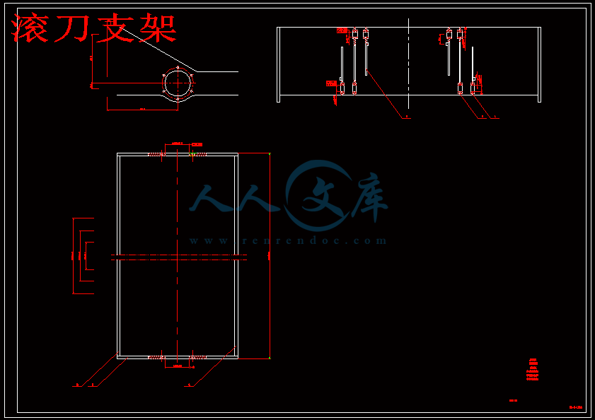
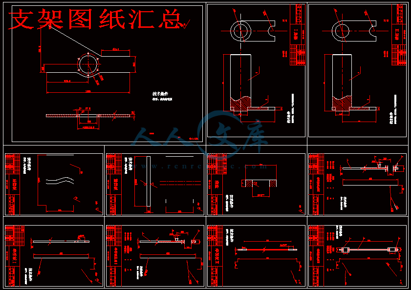
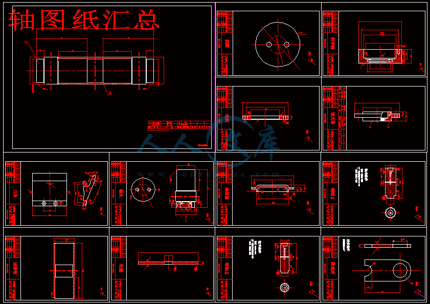
滚圈图纸如下


                目   录


绪论 ……………………………………………………………………… 1
  1.1本次设计来源、目的、意义、国内外概况………………………………1
    1.1.1 本次设计的来源…………………………………………………… 1
    1.1.2 本次设计研究目的………………………………………………… 1
    1.1.3 本次设计研究的意义…………………………………………………1
    1.1.4 有关清雪机国内外研究概况…………………………………………2
  1.2 本设计预期达到的目标……………………………………………………4
  1.3 本设计研究内容、研究方法及技术路线…………………………………5
     1.3.1 斜刃螺栓连接式厚冰雪磙压除雪机的整体方案构想………………5
     1.3.2 结构原理和计算要点…………………………………………………5
  1.4 本课题实现的现有条件……………………………………………………6
  1.5 研究的主要内容和方法……………………………………………………6
    1.5.1冰雪切削挤压破碎技术、总体方案………………………………… 6
    1.5.2 碾压滚型式和结构……………………………………………………6
    1.5.3 滚齿排列方式及刀刃几何参数………………………………………6
    1.5.4 各主要零件的校核验算………………………………………………6
第2章   路面冰雪清除机机理研究……………………………………………… 8
  2.1 冰雪的物理机械性质………………………………………………………8
  2.2 路面冰雪清除机基本方案、原理…………………………………………9
  2.3 整机分析及装置重量的确定…………………………………………… 13
      2.3.1整机的组成………………………………………………………… 13
    2.3.2清除冰雪装置重量………………………………………………… 14
第3章  碾压滚结构及参数………………………………………………………15
  3.1 碾压滚结构形式………………………………………………………… 15
  3.2 碾压滚参数……………………………………………………………… 15
  3.3 工作阻力的计算………………………………………………………… 15
第4章  齿刀的研究……………………………………………………………… 17
  4.1 齿刀在碾压滚上的排列﹑数量﹑间距………………………………… 17
  4.2 齿刀几何参数…………………………………………………………… 17
  4.3 切削力计算……………………………………………………………… 18
第5章  主要零件校核计算……………………………………………………… 19
  5.1  轴承的校核计算…………………………………………………………19
    5.1.1 当量动载荷的校核…………………………………………………19
    5.1.2 滚动轴承寿命的计算………………………………………………30
  5.2 齿刀强度的校核分析…………………………………………………… 21
  5.3 销轴的校核计算………………………………………………………… 26
  5.4 轴的校核计算…………………………………………………………… 29
    5.4.1 按扭转强度条件计算………………………………………………30
    5.4.2 按弯扭合成强度条件计算…………………………………………30
第6章  电器系统………………………………………………………………… 33
  6.1 电源电路………………………………………………………………… 33
  6.2 启动系统………………………………………………………………… 33
  6.3 照明和信号系统………………………………………………………… 33
  6.4 仪表系统………………………………………………………………… 33            
  6.5 预热器…………………………………………………………………… 34
第7章  电算部分…………………………………………………………………35
第8章  结  论……………………………………………………………………43
致谢…………………………………………………………………………………45
参考文献……………………………………………………………………………46


1 课题来源、目的、意义、国内外概况

1.1 本课题的来源
   本课题属于吉林大学机械科学与工程学院2000级本科生的毕业设计指导教师的科研项目(国家经贸委“国家重点技术改造项目[2003]86”)。是根据国际和国内的最新形势和市场需求而确定的研究课题。对实际的生产和生活有很大的实际意义。是隶属于国家攻关课题-----多功能铲雪车研制的一部分。

1.2 本课题研究目的
   中国北方大部分地区,每年有3~5个月的降雪期,道路积雪给交通运输及人民日常生活带来许多困难,有时甚至阻断交通。近几年来高等级公路里程不断增加,及时有效地清除路面积雪已成为亟待解决、刻不容缓的问题,这对于提高车辆的运输效率、避免重大交通事故的发生,具有很大的社会经济效益。目前,国内除雪作业多由人工或其它代用机械完成,其劳动强度大,作业效率低。进口外国先进的除雪设备,造价高且不适合中国国情;而用其它的代用机械如平地机进行除雪作业,则又浪费实用设备且对路面具有破坏性。所以,尽快开发出适合中国国情的低成本、高效率、且宜大面积推广应用的除雪设备,是一项艰巨而紧迫的任务。

1.3 本课题研究的意义
   我国北方大部分地区,每年有很长的降雪期,道路积雪给交通运输及人民日常生活带来许多不便。尤其冻结在道路上的积雪与薄冰,采用传统除雪机用推刮的办法无法清除,为此不得不耗费大量人力物力进行人工铲除。采用机械方法清除是一项急需解决的难题。就目前国内除雪机械来看,大多数功能单一,或只能清除积雪、或只能破除积冰[1]。国外的除雪机功能较全,但结构复杂,造价昂贵,且大多不适合国内的道路状况。因此开发研制适合我国道路情况的集破冰除雪于一机的设备,具有十分重大的意义。国外的除雪机功能较全,但结构复杂,造价昂贵,且大多不适合国内的道路状况。因此开发研制适合我国道路情况的集破冰除雪于一机的设备,同样具有十分重大的意义。

1.4 本课题国内外研究概况

   1.4.1 本课题国内外研究概况
   目前,世界各个国家除冰雪的方法中,应用最普遍的是溶解法和机械法。溶解法是依靠热作用或撒部化学药剂使冰雪融化。其优点是除净率高,但是它的成本很高。而且容易造成环境污染。虽然环保型融雪药剂已经问世,对环境和植被的影响减少了,但是并未彻底根除。因此使用范围受到一定限制。
   机械法是通过机械作用直接作用解除冰雪危害。虽然除净率较低,但是对环境和植被无任何影响。能实现冰雪的异地转移。应用范围比较广。因此,笔者认为:清除冰雪必须以机械法为主,以溶解法为辅助,才能达到快速和环保的除雪效果。
   我国对除雪机械的开发、生产都比较晚,因此还处于起步阶段。目前,我国的城市道路和公路冬季除雪大部分仍沿用传统的养护方式,即人工作业和小型的除雪机械相结合的方式。高速公路和一级公路开始使用大型专用除雪机械,进行冬季养护。但是,除雪机械在数量和品种规格上还很少,所以除雪设备大部分依赖进口。机械化程度和总体水平远远落后于发达国家。只是最近几年国内的厂家才参照国外的先进技术研制了适合我国国情的除雪机械。
   综观国内外的除雪机械,其类型总的来说有三种类型:
   (1) 犁式除雪机
   犁式除雪机的工作装置一般安装在主机的前端,是所有除雪机中应用最为广泛、起源最早的除雪设备。主要使用于未被压实的新降集雪,其厚度为300mm以下。犁板有整体式和分段式,有V型犁和U型犁之分。其特点是:多数采用了双摇杆机构,避让效果明显,越障高度较大,环境适应性强,可以在硬质雪区工作。有的还增加了滑靴和滚轮等装置,用来减少或消除铲刃对地面的作用力,保护了地面,减少了刀刃的磨损。
   具体类型有:
   1) 向犁-----除雪犁以固定角度装在除雪车前部。
   2) V型犁-----主要结构和工作原理与单向犁相同,只是结构呈左右对称,形成V形。
   3)变角度犁------指犁的排雪方向和行进角度可以改变的除雪机械
   4)复合犁------又叫铰接雪犁,采用两翼结构,中间垂直铰链可以自由改变形状,形成单向犁、V型犁、变角度犁等犁形。
   比较典型的产品有:徐州装载机长的专利产品------调压自动越障式除雪装置。郑工、柳工和沈阳山河等厂家生产的ZL50型除雪机。由于该类除雪机械拥有结构简单、性能可靠、价格低廉等特性,因此受到广大用户的认可,得以广泛的使用。
   (2) 旋切式除雪机械
   旋切式除雪机械工作方式为自行式和悬挂式两种。主要有离心式物料风机、风道、抛雪筒、护板和螺旋型集雪器等部分组成。结构相对比较复杂。工作时借助主机或者专用底盘的动力,驱动风机做高速旋转运动,将集雪器聚拢的雪由风道、抛雪筒抛出去。抛出距离和角度可以根据需要自己调整。在清除雪障时旋切式除雪机械有明显的优势。但是无法清除压实的积雪。
   具体类型有:
   1) 螺旋式-----螺旋轴鼓上的叶片呈左右旋向,左右旋向的叶片在轴线中部结合形成U形抛雪槽,U形抛雪槽低部稍微向后倾斜,内侧光滑,工作时轴鼓上的叶片刀刃切削破碎积雪,并将积雪集中送到中部U形槽内抛出。
   2) 转子式-----主要以清除新雪为主要作业对象。转子叶片可以完成切雪、扒雪和抛雪。
   3) 单螺旋转子式-------有转子和一根螺旋组成。螺旋水平布置在转子前,螺旋 叶片作成左右旋向,当螺旋周转动时,把两边的积雪送到中间,再由转子抛出。
   4) 双螺旋转子式-------双螺旋转子式的工作装置的两螺旋上、下平行地置于转子前面。
   5) 立轴螺旋转子式-------该工作装置将螺旋竖放在转子两侧,螺旋叶片为左右旋向,工作时雪的移动方向为上下运动。
   主要机型有:哈尔滨开达公司生产的抛雪式除雪机和吉林大学研制的CX-30型除雪机。
   (3) 扫滚式除雪机械
   扫滚式除雪机械工作方式为自行式和悬挂式两种。在主机或者专用底盘的动力作用下,驱动扫雪滚和扫雪盘做高速旋转运动,扫雪滚和扫雪盘上的柔性强力扫雪刷,将路面积雪卷起使之脱离地面,在高压空气的作用下吹向路边。该式除雪机械主要适合于较薄的或者是犁式除雪机械工作后的残留积雪。即使路面凸凹不平也可以获得无残雪的除雪效果。主要生产厂家有:哈尔滨开达公司和哈尔滨重型机械厂等。
   国内的除雪机械虽然有了很大的发展,但其总体水平与发达国家相比,产品品种及性能都还有很大差距。适应不了我国高速公路的发展的需求,主要体现在以下几个方面:
   1)技术水平低,除雪机械在结构设计、制造工艺、零部件供应和使用管理等方面都存在技术水平低的问题。致使除雪机械可靠性差、故障多、寿命短。
   2)功能单一。除雪机械具有明显的季节性,如果功能单一,只能用做除雪和除冰专用,那么,机械一年中大部分时间处于闲置状态,大大增加了除雪 的成本。加重了公路养护部门的负担。
   3)品种类型不全。与国外相比,现在有不少除冰雪机械在国内还是一片空白。现有的除冰雪机械无法满足公路和大型机场的除冰雪的要求。

   1.4.2 国内外在这个方面的发展方向:
   (1) 加强对雪质、雪性的基础研究。
   为了提高除冰雪机械的设计水平,需要对冰雪的力学性质和物理特性进行深入研究。特别是对压实冰雪的理论研究。据有关资料研究:东北地区压实冰雪占总的除雪任务的80%以上。
   (2) 向一机多能和机电液一体化方向发展。
   在现有的条件下,可以对汽车、拖拉机、装载机和推土机等设备进行改装,冬季降雪时用来除冰雪作业,其余时间可用来进行公路养护和其他作业。可以提高设备的利用率。采用机械、电子、液压等技术提高除雪机械的科技含量,减轻工人的劳动强度。
   (3) 向大型、小型和高速方向发展。
   我国的地理环境复杂,各个城市道路建设布局各异,冬季降雪情况不同,在除雪设备的选取上也不尽相同,因此要开发出大型、小型的各种除冰雪机械,以满足不同地区和工况的除冰雪要求。同时要开发出效率高的机械,避免除雪作业造成路面交通拥挤。例如,东北有些城市规定:对于市区内主干道,雪停止24H后需运出城市外。
   (4) 加强行业间的技术交流与合作。走共同研发之路。
   各个厂家根据自己的实际情况开发出的产品各有优缺点,为了加快除冰雪机械的开发和应用,应加强企业间的合作,集中财力、物力和人力走共同发展之路,实现除冰雪的机械化。

2 本课题预期达到的目标
   在ZL40型装载机的前端安装除雪装置-----斜刃螺栓连接式压磙除厚冰雪装置。
   采用斜刃式除雪装置,使冰雪在破冰刀刃的作用下破碎。压磙与ZL40型装载机大臂相连。设计出包括铲及其连接机构。画出全部图纸:装配图、部件图、零件图、总明细表。
   设计时要保证相应构件的可靠性,所以要进行相应的力学分析、设计计算 、方针模拟等。并要求用计算机软件对重要部件进行详细的运动学和动力学分析。设计相关的软件。
   通过这次设计,要不仅温习好大学四年所学的大不分的理论知识,还要培养工程实际应用的能力,锻炼实际的动手和全局的驾御能力。对装载机和除雪机械有更深的认识,加强在此方面的设计能力。

3 本课题研究内容、研究方法及技术路线

3.1 斜刃螺栓连接式厚冰雪磙压除雪机的整体方案构想
   斜刃螺栓连接式厚冰雪磙压除雪机是针对我国道路情况设计的破冰清雪除雪设备。该设备主要起破冰作用的碾压辊构成。
   该设备的主机架可与ZL40装载机直接联接。该设备碾压辊固定在联架臂上,联架臂通过大臂与主机架铲接。碾压辊上装有刀板,刀板上的刀条直接作用在冰面上,利用自身的重力和空气锤的振动的冲击力达到破冰目的。

3.2 结构原理和计算要点
   斜刃螺栓连接式厚冰雪磙压除雪机是利用前部安装的碾压辊上装有的刀板对雪进行切削,利用自身的重力和空气锤的振动的冲击力达到破冰目的。
   (1) 叶片结构:
   采用斜刃螺栓连接式,材料用耐磨仿形材料。按与地面平行布置在压磙上,前后两排叶片位置错开。
   (2) 除雪机功率的计算:
   除雪机所消耗的功率包括两大部分:行走装置和工作装置所消耗的功率。行走装置所消耗的功率可以参照一般自行式车辆的计算办法。下面对除雪工作装置的所消耗的功率Na做一分析:
                      Na=Ne+Nf+Nr+Nd

其中: Ne-----推雪板切削所需功率。KW
       Nf-----克服雪与板面的摩察力所需的功率。KW
       Nr----推雪板前雪堆移动所需的功率,KW
       Nd----板刃与存雪地面间的摩察力所需的功率。KW

3.3 拟采用的研究方法
   采用新旧技术相结合的方法。因为有关装载机和除雪机构的研究在我国已经有了一定的进展------即使和发达国家相比还很落后-----在很多领域。但近几年我们引进了很多先进的技术,特别是除雪机械方面的,加上我们的有关装载机和其他工程机械的研究知识,将这两方面的知识有机地结合起来,实现新的突破,研制出适合我国国情的公路养护机械-----集工程作业和除雪能力于一体的多功能机械产品。

3.4 拟采用的技术路线
   4研究冰雪的物理和力学特性------查阅国内外有关装载机和除雪机械、机构的设计资料和最新进展------消化、吸收个方面的技术资料,并加以整理和创新------技术设计和整机设计。

4 本课题实现的现有条件
   国内外关于ZL40装载机的数据和文献资料的搜集较为便利。在理论上和方法上具有很强的借鉴意义。指导老师李萌老师对我国这方面的情况很了解,是这方面的专家。有很深的理论和实践知识,为本课题的研究奠定了很好的理论和实证基础。本人对于装载机和除雪机械也有一定的认识,相信一定能在李老师的指导下顺利完成课题的研究。并取得优异的毕业设计成绩!同时为我国在此领域的研究作出自己应有的贡献!


内容简介:
装订线斜刃螺栓连接式厚冰雪碾压除雪机设计摘要 我国北方地区冬季降雪时间长,雪量大,气温低,积雪数日经车辆、行人碾压而被压实。路面上压实冰雪的清除问题关系到社会生产、人民生活、交通安全、环境保护等多个方面。目前国内外对压实冰雪的清除还缺少行之有效的办法。本文结合我国北方地区降雪后的特点及我国国情,主要针对路面上被压实的冰雪研究了路面冰雪清除机械。本文提出了对路面压实冰雪进行挤压、切削、破碎的技术原理。根据这一原理确定了路面冰雪清除机械基本方案并分析了其工作机理。提出利用装载机为动力机,只需更换上清除冰雪装置,实现了一机多用。研究了传动系统各部件的匹配以及冰雪清除装置与整机的匹配,进行了匹配计算和整机牵引性能分析。根据整机方案及相关条件确定了清除冰雪装置中关键部件碾压滚的构造、重量和有关技术参数;分析研究了碾压滚上刀齿的结构和关键几何参数,确定了刀齿在碾压滚上的排列方式、数量和间距,并根据冰雪的物理机械性质计算了刀齿切削力。关键词 冰雪清除 切削 破碎 路面 1 AUTOMATIC STEERING SYSTEM FOR ROTARY SNOW REMOVERS Hirofumi HIRASHITA, Takeshi ARAI, Tadashi YOSHIDA Advanced Technology Research Team, Public Works Research Institute 1-6,Minamihara, Tsukuba City, Ibaraki-Pref, Japan, 305-8516 Tel:+81-298-79-6757 Fax:+81-298-79-6732 E-mail:hirasitapwri.go.jp, arai0333pwri.go.jp, yoshidapwri.go.jp ABSTRACT: In cold and snowy parts of Japan, most snow is removed from roads by mechanical snow removers, and to deal with roadside conditions and guarantee safe operation, these machines are normally operated by two people: an operator and an assistant. Work is in progress to develop automatic steering systems for snow removers in order to lighten the burden on snow remover operating staff and to reduce future labor requirements. This report describes an automatic steering system that incorporates three technologies: the lane marker system that has been developed in recent years as an ITS technology, RTK-GPS technology, and GIS technology. This steering system has been developed for rotary snow removers: the type of snow remover considered to be the most difficult to operate. The report also evaluates the three control methods based on the results of corroborative testing done using actual snow removers and outlines problems with these control systems that must be overcome to establish a working system. KEYWORDS: Rotary snow remover, automatic steering, ITS, lane marker, GIS, GPS 1. INTRODUCTION In cold snowy parts of Japan, snow is removed from roads by mechanical means to guarantee smooth winter road traffic. To guarantee that mechanical snow removal is performed appropriately according to the state of snow accumulation on road surfaces, a carefully planned attendance control method must be established and the machinery must be operated correctly. The automatic steering system that has been developed is intended for use on rotary snow removers: a type with an operating method more complex than that of other types of snow removers. It has been developed to reduce the burden on snow remover operators and to lower future labor requirements. 2. BACKGROUND TO THE DEVELOPMENT A rotary snow remover is operated by two people: an operator who drives the remover and an assistant who controls the ejection of the snow. The operator drives the machine along the curb on the shoulder of the road while watching out for manholes or other level differences on its surface. The assistant ejects the snow while avoiding private property, homes, and other areas where snow disposal is forbidden (Photo 1). The goal is to automate part of the vehicle operating work now performed by the operators to allow them to control the snow ejection now done by the assistants, permitting the introduction of one-man operation in the future. This report introduces positioning technology and control technology that form the foundation of the automatic steering system that has been developed, and presents an evaluation of the system based on the results of corroborative testing performed with an actual snow remover and describes problems to be overcome to complete a working system. Photograph 1. Inside of a Rotary Snow Remover 2 3. AUTOMATIC STEERING SYSTEM The automatic steering system that has been developed automates the rotary snow remover steering operation that is one of the tasks of the operator. 3.1 Steering control of a rotary snow remover The steering mechanism of a rotary snow remover differs from normal vehicles in that the front and back parts are linked by pins and articulating mechanisms are installed so that the vehicle can bend at the pins. The steering is controlled by the exact linearization method and by time scale transformation that are effective ways to control the course of a moving vehicle 1). This control method is represented by an equation of motion subject to non-holonomic constraint and is based on non-linear control theory. But a snow remover slides laterally, because as it removes snow, it is subjected to lateral reaction force from the snow embankment as shown by Photograph 2. Sideways sliding is controlled by using the integrated servo system described below to treat this sliding as an external distur-bance. (1) Course tracking control Fig. 1 shows a model of the snow remover steering mechanism. In this figure, the distances from the connecting pin of the snow remover to the front wheels and to the rear wheels are represented by L. When the steering angle is represented by 2, the course followed by the snow remover is an arc with radius R = L/tan. When the course tangent direction speed vector at the center point P of the front wheels is represented by and the tangent direction angle by , the equation of motion of the point P can be written as follows. cosvx =? sinvy =? LvRvtan=? (1) If exact linearization and time scale transformation are done for equation (1) to perform status feedback control, the quantity of steering of the snow remover that is 1/2 of the steering angle is defined by the following equation. ()3211costanfftanLy += (2) In equation (2), lateral sliding is not considered. In order to eliminate the steady-state deviation caused by lateral sliding, if the integrated servo system is used, the quantity of steering is represented by the following equation. ()?+=?tanffdtcosfcostan210ref331yvyyLt (3) The symbol f is the control gain, and based on equation (3), f1 represents proportional gain, f2 represents derivative gain, and f3 represents integral gain. PID control was used to construct the system. Figure 2. Integrated Servo System Control Block Diagram 212vRLLxyXYPFigure 1. Coordinate System (Model of a Snow Remover) tan-1除雪車 f1 f2 Lcos3tan y cmd cosf3 v s 1 yref Snow remover Photograph 2. Rotary Snow Remover Removing Snow 3 3.2 Positioning method It is necessary to detect a vehicles present position and to have information that determines the direction to steer it in order to perform automatic steering. The system that has been developed is equipped with two functions: the guidance method that use lane marker sensors to detect the vehicles position and the steering method that uses GPS and GIS to detect the vehicles position. 3.3 Lane marker sensor guidance method A lane marker sensor is a basic technology of the Advanced Cruise-Assist Highway System (AHS) developed for use as part of the Intelligent Transportation System (ITS). This technology includes lane markers buried at intervals under a road surface and vehicle mounted sensors that detect signals transmitted by these lane markers to guide the vehicle along the course formed by the markers. There are two versions of this system: the radio wave method and the magnetic method. (1) Steering angle calculation logic It is assumed that the distance between the lane markers will not be constant, but can be varied according to the shape of the road and demands of the sensor side. Therefore, this system is equipped with two rows of sensors so that control can be performed even when the lane marker installation interval is not known until the rotary snow remover passes over them (Fig. 3). To control steering with a single row of sensors (Fig. 3 on the left), the lateral differential and the azimuthal differential ym and m that are necessary for control by the target course coordinate system (xy) require information about the interval between the markers in addition to the sensor signal ym1 that is measured by the front vehicle fixed coordinate system f(xfyf). But with two rows of sensors (Fig. 3 on the right), the system can calculate the lateral differential and the azimuthal differential ym and m of the target course coordinate system (xy) by having two opposed sensors hold the two sensor signals ym1 and ym2 measured by the front vehicle fixed coordinate system f(xfyf) as it passed a marker until they pass the next marker, so that steering control can be performed even if the interval between markers was unknown. (2) Radio wave marker sensor positioning method With the radio wave method, an antenna inside the sensor on the vehicle transmits a 227.5 kHs radio wave towards the road and when a radio wave marker (Photo 3) receives this transmission, it returns a signal of double frequency of 455 kHz. A receiving antenna inside the sensor receives this return radio wave to detect the vehicles position (Fig. 6). The system detects the locations of the markers in the traveling direction by passing through the peak value. It detects the position in the lateral direction by calculating the distance between the antennas by the triangulation method based on the difference in the received strength of the return radio waves sensed by the two receiving antennas 2). Photograph 3. Radio Wave MarkerPhotograph 4. Radio Wave Marker Sensor Figure 3. Lane Marker Sensor Guidance Method mtan-1(ym1ym2)/Lm ymym1Lo(ym1ym2)/LmcosmLm:1.34m、Lo:-1.0m ym 目標軌道 No.1 No.2 ym1 ym2 Lmm Lo yf xf msin-1(ym1ym1b)/2.0 ymym1Lo(ym1ym1b)/2.0cosm Lo:-1.0m ym 目標軌道 No.1 ym1 ym1b 2m m Lo yf xf No.1 前回検出値 ym 目標軌道 No.1 No.2 ym1 ym2 Lmm Lo yf xf 敷設 Target course Target course Buried marker Front part of the snow remover Front wheel tires Value previously detected by the No. 1 sensor 4 (3) Magnetic marker sensor positioning method With the magnetic method, magnetic markerspermanent ferrite magnets (Photo 5)under the road surface produce magnetic fields and a magnetic sensor that detects magnetic field density installed on the vehicle determines the position of the vehicle based on the strength of each magnetic field. The magnetic field distribution of the magnetic marker shows the unimodality that treats the center of the marker as the maximum magnetic field strength. The magnetic flux densities of the vertical component (Bz) and the vehicle width direction component (Bx) of this magnetic field are detected by the magnetic sensor and the location of the marker is detected by calculating the distance between the sensor and the marker based on the previously stipulated Bx/Bz relational equation (Fig. 4) 3). 3.4 GPS/GIS position detection method A system based on GPS/GIS positioning detects the position of the vehicle to control its operation by comparing rotary snow remover position coordinate data received from a GPS satellite with position coordinates of linear data for the road provided in advance by road GIS. (1) Road GIS Road GIS is a data base of information concerning structures and traffic management used for road maintenance. To develop this system, rotary snow remover target course information was created so that it can be handled as GIS data. Operators of rotary snow removers remove snow to widen the bare road by driving their vehicles guided by the snow removal edge (Fig. 5) Because the snow removal edge is often the curb of the sidewalk along the sides of the road, the GIS data that was used is curb data. (2) RTK-GPS RTK-GPS, a system capable of high-precision positioning (error radius between 2 and 3 cm), consists of two GPS receiving antennae, one a fixed station and one a mobile station (on the snow remover). The fixed station transmits correction information based on GPS data it has received to the mobile station. The system can perform almost real time positioning, because the GPS data is corrected at a rate of 20Hz. 4. CORROBORATIVE TESTING Corroborative testing planned to simulate snow removal on a real road was carried out using a rotary snow remover equipped with the steering control system in Hokkaido in January and February 2002. The corroborative testing was performed in order to evaluate the applicability and practicality of each automatic steering method under the behavior characteristic of a snow remover on an actual road (low speed, lateral sliding). 4.1 Outline of the corroborative testing (1) The rotary snow remover The body of the rotary snow remover was the medium size model (2.2 m wide) used most frequently on national highways, and the body constructed according to normal specifications was partially modified (Fig. 6). Photograph 5. Magnetic Marker -2-1.5-1-0.500.511.52-300-250-200-150-100-50050100150200250300横位 置 H=300mmH=500mmLateral location Figure 4. Bx/Bz Relationship 除 雪 目 標 作 業 Snow removers target work line Figure 5. Road GIS Data 5 (2) Corroborative test course The corroborative test course consisted of straight sections, curves, (R 30 m), and intersections (R 12 m) so that it reproduced conditions on national highways. Its lane marker intervals were 2.0 m and 1.5 m. The rotary snow remover work conditions were identical to those of actual work, with the work done at two speeds, 4 km/h and 0.5 km/h 4). Snow banks were prepared to provide the work load and lateral sliding that occur when a remover is used to widen the cleared part of a road. 4.2 Results of the corroborative testing The testing corroborated the lane marker sensing (radio wave and magnetic) guidance methods and the GPS/GIS positioning method. Because the steering control system developed is a system that follows a preset target course, its control performance was evaluated as the quantity of deviation of the snow remover from its target course (quantity of lateral deviation). Table 1 shows the quantities of lateral deviation from the test results organized by method. Table 1. Lateral Discrepancy for Each System (Example) Stand-alone operation (working speed 4 km/h, quantity of deviation of front sensor) Unit m Road alignment Straight section Curve to the left Curve to the right Straight sectionInter-sectionMax. value 0.25 0.41 0.28 0.390.76Min. value 0.23 0.49 0.38 0.020.26Average value0.05 0.06 0.13 0.160.51Radio wave typeStandard differential 0.12 0.23 0.19 0.120.16Max. value 0.06 0.35 0.37 0.420.91Min. value 0.18 0.37 0.53 0.110.29Average value0.04 0.08 0.25 0.270.61Magnetic type Standard differential 0.06 0.21 0.24 0.100.22Max. value 0.04 0.04 0.25 0.240.17Min. value 0.03 0.32 0.26 0.000.24Average value0.00 0.08 0.04 0.070.02GPS Standard differential 0.02 0.11 0.10 0.080.09 This table shows that overall, the quantity of deviation and the standard deviation were both small on the straight sections, but both were higher on curves and at intersections. This difference is presumably a result of the fact that in sections with a small radius of curvature, a larger quantity of steering is performed and the snow removal load is more likely to cause lateral sliding. By method, the GPS/GIS method is superior to the lane marker method. Because the former method achieves almost real time positioning and steering control of almost 20Hz, it can respond instantly to lateral sliding to reduce the quantity of deviation. With the latter, steering is delayed because the system cannot detect lateral sliding where there are no signals between lane markers, resulting in a large quantity of lateral deviation. Therefore, testing was done by, in addition to correcting lateral sliding with the sensor, providing the coordinates of the next marker (course information) as the sensors passed the markers. The resulting lateral sliding distribution reveals that as shown in Fig. 8, 2 (: standard differential) at this time was 57 cm without course information, and it was 31 cm with course information: a big improvement that brings its precision extremely close to that of the GPS/GIS method. No gap in performance between the speeds 4 km/h and 0.5/h was observed. Fig. 6 Rotary Snow Remover Equipped with an Automatic Steering Support Function KAKEKAKEKEKEKAR=30mR=30mR=12m900102030405060708090100110120130138走 行 詳 細 図 埋 設試験 車 幅余裕 幅(50)雪堤作成 用補 助車 両幅R=30mR=12m除雪端部KAKEKAKEKEKEKAR=30mR=30mR=12m900102030405060708090100110120130138走 行 詳 細 図 埋 設試験 車 幅余裕 幅(50)雪堤作成 用補 助車 両幅R=30mR=12m除雪端部Line of buried lane markers Snow removal edge Start Goal Figure 7. Layout of the Test Course Mobile RTK-GPS StationLane maker sensing systemAutomatic steering control systemServo valveMobile RTK-GPS StationLane maker sensing systemAutomatic steering control systemServo valve 6 5. CONCLUSIONS AND FUTURE CHALLENGES It has been confirmed that automatic steering systems using lane markers or GPS, GIS, etc. can achieve a generally practical level of control of normal snow removal work by rotary snow removers. But in order to establish practical working systems, the following challenges must be resolved. (1) Testing of the GPS/GIS method showed that its detection precision temporarily fell even in open spaces. It is assumed that this happened when the GPS satellites were concentrated in a narrow range. And during testing of the radio wave marker method, unpredictable behavior thought to be an effect of the high output transmitter on the vehicle was observed. It is necessary to provide a function that automatically stops operation without the intervention of the operator when such abnormal operating signals are produced. (2) And as in the GPS/GIS case, it is necessary to improve the precision of control by the lane marker method by entering the lane marker coordinates to the snow remover system in advance to provide it with course information. It is also essential to record passage over each marker each time the system passes over the markers. (3) And to further improve control precision (reduce the quantity of deviation), it is necessary to strive to quantify disturbance such as lateral sliding and the snow removal load etc. of the snow remover and to perform simulations after increasing the degree of detail of the model of snow removal work by a rotary snow remover. 6. CONCLUSION In recent years, various organizations
温馨提示:
1: 本站所有资源如无特殊说明,都需要本地电脑安装OFFICE2007和PDF阅读器。图纸软件为CAD,CAXA,PROE,UG,SolidWorks等.压缩文件请下载最新的WinRAR软件解压。
2: 本站的文档不包含任何第三方提供的附件图纸等,如果需要附件,请联系上传者。文件的所有权益归上传用户所有。
3.本站RAR压缩包中若带图纸,网页内容里面会有图纸预览,若没有图纸预览就没有图纸。
4. 未经权益所有人同意不得将文件中的内容挪作商业或盈利用途。
5. 人人文库网仅提供信息存储空间,仅对用户上传内容的表现方式做保护处理,对用户上传分享的文档内容本身不做任何修改或编辑,并不能对任何下载内容负责。
6. 下载文件中如有侵权或不适当内容,请与我们联系,我们立即纠正。
7. 本站不保证下载资源的准确性、安全性和完整性, 同时也不承担用户因使用这些下载资源对自己和他人造成任何形式的伤害或损失。
提示  人人文库网所有资源均是用户自行上传分享,仅供网友学习交流,未经上传用户书面授权,请勿作他用。
关于本文
本文标题:路面冰雪除雪机设计【毕业论文和全套7张CAD图纸】
链接地址:https://www.renrendoc.com/p-271519.html

官方联系方式

2:不支持迅雷下载,请使用浏览器下载   
3:不支持QQ浏览器下载,请用其他浏览器   
4:下载后的文档和图纸-无水印   
5:文档经过压缩,下载后原文更清晰   
关于我们 - 网站声明 - 网站地图 - 资源地图 - 友情链接 - 网站客服 - 联系我们

网站客服QQ:2881952447     

copyright@ 2020-2024  renrendoc.com 人人文库版权所有   联系电话:400-852-1180

备案号:蜀ICP备2022000484号-2       经营许可证: 川B2-20220663       公网安备川公网安备: 51019002004831号

本站为文档C2C交易模式,即用户上传的文档直接被用户下载,本站只是中间服务平台,本站所有文档下载所得的收益归上传人(含作者)所有。人人文库网仅提供信息存储空间,仅对用户上传内容的表现方式做保护处理,对上载内容本身不做任何修改或编辑。若文档所含内容侵犯了您的版权或隐私,请立即通知人人文库网,我们立即给予删除!