轴承内外圈加工专用机床纵向机构设计说明书.doc

轴承内外圈加工专用机床纵向机构设计【带UG三维+仿真】【27张图纸】【优秀】

收藏

资源目录
跳过导航链接。
轴承内外圈加工专用机床纵向机构设计【带UG三维+仿真】【27张图纸】【优秀】.rar
压缩包内文档预览:(预览前20页/共48页)
预览图 预览图 预览图 预览图 预览图 预览图 预览图 预览图 预览图 预览图 预览图 预览图 预览图 预览图 预览图 预览图 预览图 预览图 预览图 预览图
编号:271552    类型:共享资源    大小:6.74MB    格式:RAR    上传时间:2014-04-07 上传人:上*** IP属地:江苏
50
积分
关 键 词:
轴承 内外圈 加工 专用 机床 纵向 机构 设计 ug 三维 仿真 27 图纸 优秀
资源描述:

轴承内外圈加工专用机床纵向机构设计

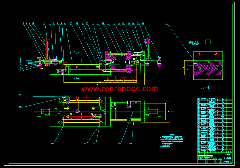
46页 18000字数+说明书+任务书+开题报告+外文翻译+UG三维模型及运动仿真+27张CAD图纸【详情如下】

UG三维模型及运动仿真.rar

任务书.doc

刹铁.dwg

外文翻译--车床及其切削加工.docx

纵向前调节丝杆.dwg

纵向台面板.dwg

纵向后调节丝杆M12螺丝.dwg

纵向后调节丝杆套.dwg

纵向后调节丝杆尼龙套.dwg

纵向后调节丝杆尼龙并帽.dwg

纵向后调节丝杆感应铁.dwg

纵向后调节丝杆顶针.dwg

纵向后调节套.dwg

纵向后调节并帽.dwg

纵向底板.dwg

纵向油缸前端盖.dwg

纵向油缸后端盖.dwg

纵向油缸拉杆.dwg

纵向油缸活塞.dwg

纵向油缸缸套.dwg

纵向油缸调节座.dwg

纵向油缸防尘罩.dwg

纵向燕尾板.dwg

纵向缸连接固定板.dwg

纵向缸连接螺丝.dwg

纵向调节手柄.dwg

纵向调节螺母.dwg

纵向闯头.dwg

纵向闯头衬套.dwg

组装图.dwg

计划周记进度检查表.xls

轴承内外圈加工专用机床纵向机构设计开题报告.doc

轴承内外圈加工专用机床纵向机构设计说明书.doc

摘  要

   随着轴承工业的迅速发展,对轴承的加工精度、效率、可靠性提出了更高的要求。尺寸精度是轴承加工中的一项关键因素,而车床的进给机构直接影响轴承套圈加工的尺寸精度。因此,随着对轴承质量要求的不断提高,需要更加精密高效的车床进给机构。

   本文是根据轴承厂轴承内外圈加工生产线项目的改造要求设计的,针对人工控制机床的进给加工,加工效率低,生产出的零件精度难于控制的问题,设计一套此车床的半自动进给机构,代替传统机床的人工操作,提高生产效率,提高零件的精度。

   论文根据轴承内外圈加工设备加工时进给的特点,对其纵向进给机构进行合理的设计。设计出利用液压驱动,前、后调节机构调节进给量的纵向进给机构。本文先对液压驱动系统、导向机构、前调节机构、后调节机构进行设计,确定具体尺寸。利用UG软件对纵向进给机构进行三维建模,并进行虚拟装配。然后对装配图在UG运动仿真界面进行运动仿真,分析仿真结果,得出相应结论。最后对纵向进给系统进行优化设计,提高其稳定性、可靠性。使其能满足轴承厂生产线繁重的工作。

关键词:进给机构;UG;虚拟装配;运动仿真

目  录

摘  要III

AbstractIV

目  录V

1 绪论1

1.1 课题来源,研究内容和意义1

1.2 轴承与轴承圈1

1.2.1 轴承1

1.2.2 轴承圈2

1.3 国内外发展概况2

1.4 本课题主要内容3

2 纵向自动进给机构设计4

2.1 现有机构及生产要求的分析4

2.2 整体设计方案及思路5

2.3 纵向进给机构各部分的设计与计算6

2.3.1 纵向进给机构外形轮廓确定6

2.3.2 导向机构设计7

2.3.3 驱动装置的选取9

2.3.4 前调节机构设计12

2.3.5 后调节机构设计12

2.4 本章小结13

3基于UG的进给机构三维建模与装配14

3.1 UG软件简介14

3.1.1 UG软件特点14

3.1.2 UG软件设计流程14

3.1.3 UG软件的应用范围14

3.1.4 UG软件设计的意义15

3.2 纵向机构的三维建模15

3.2.1 纵向底板的建模15

3.2.2 纵向燕尾板建模16

3.2.3 刹铁的建模16

3.2.4 纵向台面板的建模17

3.2.5 油缸的建模19

3.2.6 前调节机构的建模19

3.2.7 后调节机构的建模20

3.3纵向进给机构的装配20

3.4本章小结23

4 纵向自动进给机构的运动仿真24

4.1 UG运动仿真简介24

4.1.1 UG运动仿真主界面24

4.2运动仿真的流程25

4.3创建连杆26

4.4创建运动副27

4.5创建驱动及“3D”接触29

4.6 本章小结35

5 总结与展望36

5.1 总结36

5.2 不足及展望36

致  谢37

参考文献38


1 绪论

1.1 课题来源,研究内容和意义

   本课题来源于无锡迪克机械对轴承生产线改造项目。

   本论文的主要内容包括:

   根据迪克机械实际技术要求和生产设备,提出轴承内外圈加工专用机床的结构方案,并且对每个零部件进行设计。

   对轴承内外圈加工专用机床纵向进给机构进行设计,并用UG软件进行建模。

   对轴承内外圈加工专用机床纵向进给机构进行虚拟装配。

   对装配体做基于UG的运动仿真分析,检查本设计方案及其模型的合理性。

   轴承内外圈加工专用机床纵向进给机构作为自动化生产线更新项目的一部分,提供多机床看管的可能性,并可以代替精度要求高或重复的工作,因此大大提高了生产效率。

   轴承内外圈加工专用机床纵向进给机构在生产过程中,工人手动对刀,手动控制进给量,重复单调。发生生产事故或者使加工零件报废一般发生在工人长时间重复单一动作的的时候。为了改善工作环境,降低工人的劳动强度。提高生产效率和零件的精度。轴承内外圈加工专用机床自动纵向进给机构的研制使其能真正代替人工工作。工人只要按动按钮。此机构的工作方式使其能实现一人多机操作;可以使大量工人从中解放出来;提高了加工精度;降低了企业生产成本;使企业更加有竞争力!

1.2 轴承与轴承圈

  1.2.1 轴承

   轴承广泛应用于机械工业的基础传动元件,其加工质量直接影响其传动性能。它具有加速快,摩擦小等特点,对其制造的主机性能的影响程度。由于其独特的传动性能,使其在国民经济的各个领域得到广泛应用。

   轴承的种类主要分为一下几种:

   1.角接触球轴承

   角接触球轴承可同时承受径向负荷和轴向负荷。能在较高的转速下工作。接触角越大,轴向承载能力越高。高精度和高速轴承通常取15 度接触角。在轴向力作用下,接触角会增大。

   2.深沟球轴承

   深沟球轴承是滚动轴承中最为普通的一种类型。基本型的深沟球轴承由一个外圈,一个内圈、一组钢球和一组保持架构成。深沟球轴承类型有单列和双列两种,单列深沟球轴承类型代号为6,双列深沟球轴承代号为4。其结构简单,使用方便,是生产最普遍,应用最广泛的一类轴承。

   3.四点接触球轴承

   四点接触球轴承是一种分离型轴承,也可以说是一套轴承可承受双向轴向载荷的角接触球轴承。其内、外圈滚道是桃型的截面,当无载荷或是纯径向载荷作用时,钢球和套圈呈现为四点接触,这也是这个名称的由来。四点接触球轴承可以承受径向负荷、双向轴向负荷。

   4.调心球轴承

   由于外圈滚道面呈球面,具有自动调心性,因此可以补偿不同心度和轴挠度造成调心球轴承成的误差,圆锥孔轴承通过使用紧固件可方便地安装在轴上。

   5.圆柱滚子轴承

   圆柱滚子与滚道为线接触轴承。负荷能力大,主要承受径向负荷。滚动体与套圈挡边摩擦小,适于高速旋转。径向负荷能力大,即适用于承受重负荷与冲击负荷,也适用于高速旋转的机构,大多用于机床主轴。

   6.圆锥滚子轴承

   圆锥滚子轴承属于分离型轴承,轴承的内、外圈均具有锥行滚道。该类轴承按所装滚子的列数分为单列、双列和四列圆锥滚子轴承等不同的结构型式。单列圆锥滚子轴承可以承受径向负荷和单一方向轴向负荷。当轴承承受径向负荷时,将会产生一个轴向分力,所以当需要另一个可承受反方向轴向力的轴承来加以平衡。。

   7.调心滚子轴承

   调心滚子轴承具有两列滚子,主要承受径向载荷,同时也能承受任一方向的轴向载荷。有高的径向载荷能力,特别适用于重载或振动载荷下工作,但不能承受纯轴向载荷。该类轴承外圈滚道是球面形,故其调心性能良好,能补偿同轴度误差。

   8.推力球轴承

   推力球轴承采用高速运转时可承受推力载荷的设计,由带有球滚动的滚道沟的垫圈状套圈构成。由于套圈为座垫形,因此,推力球轴承被分为平底座垫型和调推力球轴承hheey心球面座垫型两种类型。另外,这种轴承可承受轴向载荷,但不能承受径向载荷。

内容简介:
无锡太湖学院信 机系 机械工程及自动化 专业毕 业 设 计论 文 任 务 书一、题目及专题:1、题目轴承内外圈加工专用机床纵向机构设计 2、专题 二、课题来源及选题依据 该课题来源于机械制造业提高加工过程的机械化和自动化水平,提高生产效率,降低工人的劳动强度,降低企业成本的需求。 轴承是现代机械中不可或缺的零件,轴承的使用量非常大,现今的轴承加工主要以人工控制加工为主,由工人的动控制进给量,单调重复,而且工人长时间重复单一动作容易发生差错,发生生产事故或者使加工零件报废。为了降低工人老大强度,改善工作环境。提高生产效率和零件的精度。研制轴承内外圈加工专用机床自动纵向进给机构使其能真正代替人工完成任务。 工人要做的就是按动按钮。这样可以实现一人多机操作,解放出大批工人,同时也降低了企业生产成本,提高了加工精度,使企业更具有竞争力! 三、本设计(论文或其他)应达到的要求:根据提供的毕业设计资料理解设计要求,查阅相关中外资料。 确定纵向机构的设计方案。 对纵向机构进行建模,生成工程图。 对纵向机构进行运动仿真。 阅读和翻译英文文献。 撰写毕业设计论文。 四、接受任务学生: 机械95 班 姓名 陈志伟 五、开始及完成日期:自2012年11月12日 至2013年5月25日六、设计(论文)指导(或顾问):指导教师签名 签名 签名教研室主任学科组组长研究所所长签名 系主任 签名年 月 日英文原文Lathes And Its Cutting ProcessLathes are machine tools designed primarily to do turning, facing,and boring. Very little turning is done on other types of machine tools,and none can do it with equal facility. Because lathes also can do drilling and reaming, their versatility permits several operations to be done with a single setup of the workpiece. Consequently, more lathes of various types are used in manufacturing than any other machine tool.The essential components of a lathe are the bed, headstock assembly, tailstock assembly, carriage assembly, and the leadscrew and feed rod.The bed is the backbone of a lathe. It usually is made of well-normalized or aged gray or nodular cast iron and provides a heavy, rigidframe on which all the other basic components are mounted. Two sets of parallel, longitudinal ways, inner and outer, are contained on the bed, usually on the upper side. Some makers use an inverted V-shape for all four ways, whereas others utilize one inverted V and one fiat way in one or both sets. They are precision-machined to assure accuracy of alignment. On most modem lathes the ways are surface-hardened to resist wear and abrasion, but precaution should be taken in operating a lathe to assure that the ways are not damaged. Any inaccuracy in them usually means that the accuracy of the entire lathe is destroyed.The headstock is mounted in a fixed position on the inner ways,usually at the left end of the bed. It provides a powered means of rotating the work at various speeds. Essentially, it consists of a hollow spindle, mounted in accurate bearings, and a set of transmission gears-similar to a truck transmission-through which the spindle can be rotated at a number of speeds. Most lathes provide from 8 to 18 speeds, usually in a geometric ratio, and on modem lathes all the speeds can be obtained merely by moving from two to four levers. An increasing trend is to provide a continuously variable speed range through electrical or mechanical drives.Because the accuracy of a lathe is greatly dependent on the spindle, it is of heavy construction and mounted in heavy beatings, usually preloaded tapered roller or ball types. The spindle has a hole extending through its length, through which long bar stock can be fed. The size d this hole is an important dimension of a lathe because it detemtines the maximum size of bar stock that can be machined when the material must be fed through spindle.The tailstock assembly consists, essentially, of three parts. A lower casting fits on the inner ways of the bed and can slide longitudinally thereon, with a means for clamping the entire assembly in any desired location. An upper casting fits on the lower one and can be movedtransversely upon it, on some type of keyed ways, to permit aligning the tailstock and headstock spindles. The third major component of the assembly is the tailstock quill. This is a hollow steel cylinder, usually about 51 to 76 mm (2 to 3 inches) in diameter, that can be moved several inches longitudinally in and out of the upper casting by means of a handwheel and screw.The size of a lathe is designated by two dimensions. The first is known as the swing. This is the maximum diameter of work that can be rotated on a lathe. It is approximately twice the distance between the line connecting the lathe centers and the nearest point on the ways. The second size dimension is the maximum distance between centers. The swing thus indicates the maximum workpiece diameter that can be turned in the lathe, while the distance between centers indicates the maximum length of workpieee that can be mounted between centers.Engine lathes are the type most frequently used in manufacturing. llley are heavy-duty machine tools with all the components described previously and have power drive for all tool movements except on the compound rest. They commonly range in size from 305 to 610 mtn ( 12 to 24 inches) swing and from 610 to 1 219 mm (24 to 48 inches) center distances, but swings up to 1 270 mm (50 inches) and center distances up to 3 658 mm ( 12 feet) are not tmcommon. Most have chip pans and a built-in coolant circulating system. Smaller engine lathes-with swings usually not over 330 mm ( 13 inches)-also are available in bench type,designed for the bed to be mounted on a bench or cabinet.Although engine lathes are versatile and very useful, because of the time required for changing and setting tools and for making measurements on the workpiece, they ale not suitable for quantity production. Often the actual chip-production time is less than 30% of the total cycle time. In addition, a skilled machinist is required for all the operations, and such persons are costly and often in short supply. However, much of the operators time is consumed by simple, repetitious adjustments and in watching chips being made. Consequently, to reduce or eliminate the amount of skilled labor that is required, turret lathes, screw machines, and other types of semiautomatic and automatic lathes have been highly developed and are widely used in manufacturing.The engine lathe, one of the oldest metal removal machines, has a number of useful and highly desirable attributes. Today these lathes are used primarily in small shops where smaller quantities rather than large production runs are encountered.The engine lathe has been replaced in todays production shops by a wide variety of automatic lathes such as automatic tracer lathes, turret lathes, and automatic screw machines. All the advantages of single-point tooling for maximum metal removal, and the use of form tools for finish and accuracy, are now at the designers fingertips with production speeds on a par with the fastest processing equipment on the scene today.Tolerances for the engine lathe depend primarily on the skill of the operator. The design engineer must be careful in using tolerances of an experimental part that has been produced on the engine lathe by a skilled operator. In redesigning an experimental part for production, economical tolerances should be used.Production machining equipment must be evaluated now, more than ever before, in terms of ability to repeat accurately andrapidly. Applying this criterion for establishing the production qualification of a specific method, the turret lathe merits a high rating.In designing for low quantities such as 100 or 200 parts, it is most economical to use the turret lathe. In achieving the optimum tolerances possible on the turret lathe, the designer should strive for a minimum of operations.High-speed machining is contemporary advanced manufacturing technology an important component of the high-efficiency, High-precision and high surface quality, and other features. This article presents the technical definition of the current state of development of Chinas application fields and the demand situation. High-speed machining is oriented to the 21st century a new high-tech, high-efficiency, High-precision and high surface quality as a basic feature, in the automobile industry, aerospace, Die Manufacturing and instrumentation industries gained increasingly widespread application, and has made significant technical and economic benefits. contemporary advanced manufacturing technology an important component part.HSC is to achieve high efficiency of the core technology manufacturers, intensive processes and equipment packaged so that it has a high production efficiency. It can be said that the high-speed machining is an increase in the quantity of equipment significantly improve processing efficiency essential to the technology. High-speed machining is the major advantages : improve production efficiency, improve accuracy and reduce the processing of cutting resistance.The high-speed machining of meaning, at present there is no uniform understanding, there are generally several points as follows : high cutting speed. usually faster than that of their normal cutting 5 -10 times; machine tool spindle speed high, generally spindle speed in -20000r/min above 10,000 for high-speed cutting; Feed at high velocity, usually 15 -50m/min up to 90m/min; For different cutting materials and the wiring used the tool material, high-speed cutting the meaning is not necessarily the same; Cutting process, bladed through frequency (Tooth Passing Frequency) closer to the machine-tool - Workpiece system the dominant natural frequency (Dominant Natural Frequency), can be considered to be high-speed cutting. Visibility high-speed machining is a comprehensive concept. 1992. Germany, the Darmstadt University of Technology, Professor H. Schulz in the 52th on the increase of high-speed cutting for the concept and the scope, as shown in Figure 1. Think different cutting targets, shown in the figure of the transition area (Transition), to be what is commonly called the high-speed cutting, This is also the time of metal cutting process related to the technical staff are looking forward to, or is expected to achieve the cutting speed.High-speed machining of machine tools, knives and cutting process, and other aspects specific requirements. Several were from the following aspects : high-speed machining technology development status and trends.At this stage, in order to achieve high-speed machining, general wiring with high flexibility of high-speed CNC machine tools, machining centers, By using a dedicated high-speed milling, drilling. These equipment in common is : We must also have high-speed and high-speed spindle system feeding system, Cutting can be achieved in high-speed process. High-speed cutting with the traditional cutting the biggest difference is that Machine-tool-workpiece the dynamic characteristics of cutting performance is stronger influence. In the system, the machine spindle stiffness, grip or form, a long knife set, spindle Broach, torque tool set, Performance high-speed impact are important factors.In the high-speed cutting, material removal rate (Metal Removal Rate, MRR), unit time that the material was removed volume, usually based on the machine-tool-workpiece whether Processing System chatter. Therefore, in order to satisfy the high-speed machining needs, we must first improve the static and dynamic stiffness of machine spindle is particularly the stiffness characteristics. HSC reason at this stage to be successful, a very crucial factor is the dynamic characteristics of the master and processing capability.In order to better describe the machine spindle stiffness characteristics of the project presented new dimensionless parameter - DN value, used for the evaluation of the machine tool spindle structure on the high-speed machining of adaptability. DN value of the so-called axis diameter per minute speed with the product. The newly developed spindle machining center DN values have been great over one million. To reduce the weight bearing, but also with an array of steel products than to the much more light ceramic ball bearings; Bearing Lubrication most impressive manner mixed with oil lubrication methods. In the field of high-speed machining. have air bearings and the development of magnetic bearings and magnetic bearings and air bearings combined constitute the magnetic gas / air mixing spindle.Feed the machine sector, high-speed machining used in the feed drive is usually larger lead, multiple high-speed ball screw and ball array of small-diameter silicon nitride (Si3N4) ceramic ball, to reduce its centrifugal and gyroscopic torque; By using hollow-cooling technology to reduce operating at high speed ball screw as temperature generated by the friction between the lead screw and thermal deformation.In recent years, the use of linear motor-driven high-speed system of up to Such feed system has removed the motor from workstations to Slide in the middle of all mechanical transmission links, Implementation of Machine Tool Feed System of zero transmission. Because no linear motor rotating components, from the role of centrifugal force, can greatly increase the feed rate. Linear Motor Another major advantage of the trip is unrestricted. The linear motor is a very time for a continuous machine shop in possession of the bed. Resurfacing of the very meeting where a very early stage movement can go, but the whole system of up to the stiffness without any influence. By using high-speed screw, or linear motor can greatly enhance machine system of up to the rapid response. The maximum acceleration linear motors up to 2-10G (G for the acceleration of gravity), the largest feed rate of up to 60 -200m/min or higher. 2002 world-renowned Shanghai Pudong maglev train project of maglev track steel processing, Using the Shenyang Machine Tool Group Holdings Limited McNair friendship company production plants into extra-long high-speed system for large-scale processing centers achieve . The machine feeding system for the linear guide and rack gear drive, the largest table feed rate of 60 m / min, Quick trip of 100 m / min, 2 g acceleration, maximum speed spindle 20000 r / min, the main motor power 80 kW. X-axis distance of up to 30 m, 25 m cutting long maglev track steel error is less than 0.15 mm. Maglev trains for the smooth completion of the project provided a strong guarantee for technologyIn addition, the campaign machine performance will also directly affect the processing efficiency and accuracy of processing. Mold and the free surface of high-speed machining, the main wiring with small cut deep into methods for processing. Machine requirements in the feed rate conditions, should have high-precision positioning functions and high-precision interpolation function, especially high-precision arc interpolation. Arc processing is to adopt legislation or thread milling cutter mold or machining parts, the essential processing methods.Cutting Tools Tool Material development high-speed cutting and technological development of the history, tool material is continuous progress of history. The representation of high-speed cutting tool material is cubic boron nitride (CBN). Face Milling Cutter use of CBN, its cutting speed can be as high as 5000 m / min, mainly for the gray cast iron machining. Polycrystalline diamond (PCD) has been described as a tool of the 21st century tool, It is particularly applicable to the cutting aluminum alloy containing silica material, which is light weight metal materials, high strength, widely used in the automobile, motorcycle engine, electronic devices shell, the base, and so on. At present, the use of polycrystalline diamond cutter Face Milling alloy, 5000m/min the cutting speed has reached a practical level. In addition ceramic tool also applies to gray iron of high-speed machining; Tool Coating : CBN and diamond cutter, despite good high-speed performance, but the cost is relatively high. Using the coating technology to make cutting tool is the low price, with excellent mechanical properties, which can effectively reduce the cost. Now high-speed processing of milling cutter, with most of the wiring between the Ti-A1-N composite technology for the way of multi-processing, If present in the non-ferrous metal or alloy material dry cutting, DLC (Diamond Like Carbon) coating on the cutter was of great concern. It is expected that the market outlook is very significant; Tool clamping system : Tool clamping system to support high-speed cutting is an important technology, Currently the most widely used is a two-faced tool clamping system. Has been formally invested as a commodity market at the same clamping tool system are : HSK, KM, Bigplus. NC5, AHO systems. In the high-speed machining, tool and fixture rotary performance of the balance not only affects the precision machining and tool life. it will also affect the life of machine tools. So, the choice of tool system, it should be a balanced selection of good products. Process Parameters Cutting speed of high-speed processing of conventional shear velocity of about 10 times. For every tooth cutter feed rate remained basically unchanged, to guarantee parts machining precision, surface quality and durability of the tool, Feed volume will also be a corresponding increase about 10 times, reaching 60 m / min, Some even as high as 120 m / min. Therefore, high-speed machining is usually preclude the use of high-speed, feed and depth of cut small cutting parameters. Due to the high-speed machining cutting cushion tend to be small, the formation of very thin chip light, Cutting put the heat away quickly; If the wiring using a new thermal stability better tool materials and coatings, Using the dry cutting process for high-speed machining is the ideal technology program.High-speed machining field of applicationFlexible efficient production lineTo adapt to the needs of new models, auto body panel molds and resin-prevention block the forming die. must shorten the production cycle and reduce the cost of production and, therefore, we must make great efforts to promote the production of high-speed die in the process. SAIC affiliated with the company that : Compared to the past, finishing, further precision; the same time, the surface roughness must be met, the bending of precision, this should be subject to appropriate intensive manual processing. Due to the extremely high cutting speed, and the last finishing processes, the processing cycle should be greatly reduced. To play for machining centers and boring and milling machining center category represented by the high-speed machining technology and automatic tool change function of distinctions Potential to improve processing efficiency, the processing of complex parts used to be concentrated as much as possible the wiring process, that is a fixture in achieving multiple processes centralized processing and dilute the traditional cars, milling, boring, Thread processing different cutting the limits of technology, equipment and give full play to the high-speed cutting tool function, NC is currently raising machine efficiency and speed up product development in an effective way. Therefore, the proposed multi-purpose tool of the new requirements call for a tool to complete different parts of the machining processes, ATC reduce the number of ATC to save time, to reduce the quantity and tool inventory, and management to reduce production costs. More commonly used in a multifunctional Tool, milling, boring and milling, drilling milling, drilling-milling thread-range tool. At the same time, mass production line, against the use of technology requires the development of special tools, tool or a smart composite tool, improve processing efficiency and accuracy and reduced investment. In the high-speed cutting conditions, and some special tools can be part of the processing time to the original 1 / 10 below, results are quite remarkable. HSC has a lot of advantages such as : a large number of materials required resection of the workpiece with ultrafine, thin structure of the workpiece, Traditionally, the need to spend very long hours for processing mobile workpiece and the design of rapid change, short product life cycle of the workpiece, able to demonstrate high-speed cutting brought advantages.中文译文车床及其切削加工车床主要是为了进行车外圆、车端面和镗孔等项工作而设计的机床。车削很少在其他种类的机床上进行,而且任何一种其他机床都不能像车床那样方便地进行车削加工。由于车床还可以用来钻孔和铰孔,车床的多功能性可以使工件在一次安装中完成几种加工。因此,在生产中使用的各种车床比任何其他种类的机床都多。车床的基本部件有:床身、主轴箱组件、尾架组件、溜板组件、丝杠和光杠。床身是车床的基础件。它通常是由经过充分正火或时效处理的灰铸铁或者球墨铸铁制成。它是一个坚固的刚性框架,所有其他基本部件都安装在床身上。通常在床身上有内外两组平行的导轨。有些制造厂对全部四条导轨都采用导轨尖顶朝上的三角形导轨(即山形导轨),而有的制造厂则在一组中或者两组中都采用一个三角形导轨和一个矩形导轨。导轨要经过精密加工,以保证其直线度精度。为了抵抗磨损和擦伤,大多数现代机床的导轨是经过表面淬硬的,但是在操作时还应该小心,以避免损伤导轨。导轨上的任何误差,常常意味着整个机床的精度遭到破坏。主轴箱安装在内侧导轨的固定位置上,一般在床身的左端。它提供动力,并可使工件在各种速度下回转。它基本上由一个安装在精密轴承中的空心主轴和一系列变速齿轮类似于卡车变速箱一所组成。通过变速齿轮,主轴可以在许多种转速下旋转。大多数车床有8-18种转速,一般按等比级数排列。而且在现代机床上只需扳动2-4个手柄,就能得到全部转速。一种正在不断增长的趋势是通过电气的或者机械的装置进行无级变速。由于机床的精度在很大程度上取决于主轴,因此,主轴的结构尺寸较大,通常安装在预紧后的重型圆锥滚子轴承或球轴承中。主轴中有一个贯穿全长的通孔,长棒料可以通过该孔送料。主轴孔的大小是车床的一个重要尺寸,因为当工件必须通过主轴孔供料时,它确定了能够加工的棒料毛坯的最大尺寸。尾架组件主要由三部分组成。底板与床身的内侧导轨配合,并可以在导轨上做纵向移动。底板上有一个可以使整个尾架组件夹紧在任意位置上的装置。尾架体安装在底板上,可以沿某种类型的键槽在底板上横向移动,使尾架能与主轴箱中的主轴对正。尾架的第三个组成部分是尾架套筒。它是一个直径通常大约在5176mm(2-3英寸)之间的钢制空心圆柱体。通过手轮和螺杆,尾架套筒可以在尾架体中纵向移人和移出几英寸。车床的规格用两个尺寸表示。第一个称为车床床面上最大加工直径。这是在车床上能够旋转的工件的最大直径。它大约是两顶尖连线与导轨上最近点之间距离的两倍。第二个规格尺寸是两顶尖之间的最大距离。车床床面上最大加工直径表示在车床上能够车削的最大工件直径,而两顶尖之间的最大距离则表示在两个顶尖之间能够安装的工件的最大长度。普通车床是生产中最经常使用的车床种类。它们是具有前面所叙述的所有那些部件的重载机床,并且除了小刀架之外,全部刀具的运动都有机动进给。它们的规格通常是:车床床面上最大加工直径为305-610mm(12-24英寸);两顶尖之间距离为6101219mm(24-48英寸)。但是,床面上最大加工直径达到1 270mm(50英寸)和两顶尖之间距离达到3 658mm(12英尺)的车床也并不少见。这些车床大部分都有切屑盘和一个安装在内部的冷却液循环系统。小型的普通车床车床床面最大加工直径一般不超过330mm(13英寸)被设计成台式车床,其床身安装在工作台或柜子上。虽然普通车床有很多用途,是很有用的机床,但是更换和调整刀具以及测量工件花费很多时间,所以它们不适合在大量生产中应用。通常,它们的实际加工时间少于其总加工时间的30。此外,需要技术熟练的工人来操作普通车床,这种工人的工资高而且很难雇到。然而,操作工人的大部分时间却花费在简单的重复调整和观察切屑产生过程上。因此,为了减少或者完全不雇用这类熟练工人,六角车床、螺纹加工车床和其他类型的半自动和自动车床已经很好地研制出来,并已经在生产中得到广泛应用。普通车床作为最早的金属切削机床中的一种,目前仍然有许多有用的和为人们所需要的特性。现在,这些机床主要用在规模较小的工厂中,进行小批量的生产,而不是进行大批量的生产。在现代的生产车间中,普通车床已经被种类繁多的自动车床所取代,诸如自动仿形车床,六角车床和自动螺丝车床。现在,设计人员已经熟知先利用单刃刀具去除大量的金属余量,然后利用成型刀具获得表面光洁度和精度这种加工方法的优点。这种加工方法的生产速度与现在工厂中使用的最快的加工设备的速度相等。普通车床的加工偏差主要依赖于操作者的技术熟练程度。设计工程师应该认真地确定由熟练工人在普通车床上加工的试验零件的公差。在把试验零件重新设计为生产零件时,应该选用经济的公差。对生产加工设备来说,目前比过去更着重评价其是否具有精确的和快速的重复加工能力。应用这个标准来评价具体的加工方法,六角车床可以获得较高的质量评定。在为小批量的零件(100200件)设计加工方法时,采用六角车床是最经济的。为了在六角车床上获得尽可能小的公差值,设计人员应该尽量将加工工序的数目减至最少。高速切削加工是当代先进制造技术的重要组成部分,拥有高效率、高精度及高表面质量等特征。本文介绍此技术的定义、发展现状、适用领域以及中国的需求情况。高速切削加工是面向21世纪的一项高新技术,它以高效率、高精度和高表面质量为基本特征,在汽车工业、航空航天、模具制造和仪器仪表等行业中获得了愈来愈广泛的应用,并已取得了重大的技术经济效益,是当代先进制造技术的重要组成部分。高速切削是实现高效率制造的核心技术,工序的集约化和设备的通用化使之具有很高的生产效率。可以说,高速切削加工是一种不增加设备数量而大幅度提高加工效率所必不可少的技术。高速切削加工的优点主要在于:提高生产效率、提高加工精度及降低切削阻力。 有关高速切削加工的含义,目前尚无统一的认识,通常有如下几种观点:切削速度很高,通常认为其速度超过普通切削的5-10倍;机床主轴转速很高,一般将主轴转速在10000-20000r/min以上定为高速切削;进给速度很高,通常达15-50m/min,最高可达90m/min;对于不同的切削材料和所釆用的刀具材料,高速切削的含义也不尽相同;切削过程中,刀刃的通过频率(Tooth Passing Frequency)接近于“机床刀具工件”系统的主导自然频率(Dominant Natural Frequency)时,可认为是高速切削。可见高速切削加工是一个综合的概念。1992年,德国Darmstadt工业大学的H. Schulz教授在CIRP上提出了高速切削加工的概念及其涵盖的范围,如图1所示。认为对于不同的切削对象,图中所示的过渡区(Transition)即为通常所谓的高速切削範围,这也是当时金属切削工艺相关的技术人员所期待或者可望实现的切削速度。高速切削加工对机床、刀具和切削工艺等方面都有一些具体的要求。下面分别从这几个方面阐述高速切削加工技术的发展现状和趋势。现阶段,为了实现高速切削加工,一般釆用高柔性的高速数控机床、加工中心,也有釆用专用的高速铣、钻床。这些设备的共同之处是:必须同时具有高速主轴系统和高速进给系统,才能实现材料切削过程的高速化。高速切削与传统切削最大的区别是,“机床刀具工件”系统的动态特性对切削性能有更强的影响力。在该系统中,机床主轴的刚度、刀柄形式、刀长设定、主轴拉刀力、刀具扭力设定等,都是影响高速切削性能的重要因素。 在高速切削中,材料去除率(Metal Removal Rate,MRR),即单位时间内材料被切除的体积,通常受限于“机床-刀具-工件”工艺系统是否出现“颤振”。因此,为了满足高速切削加工的需求,首先要提高机床动静刚度尤其是主轴的刚度特性。现阶段高速切削之所以能够成功,一个很关键的因素在于对系统动态特性问题的掌握和处理能力。为了更好地描述机床主轴的刚度特性,工程上
温馨提示:
1: 本站所有资源如无特殊说明,都需要本地电脑安装OFFICE2007和PDF阅读器。图纸软件为CAD,CAXA,PROE,UG,SolidWorks等.压缩文件请下载最新的WinRAR软件解压。
2: 本站的文档不包含任何第三方提供的附件图纸等,如果需要附件,请联系上传者。文件的所有权益归上传用户所有。
3.本站RAR压缩包中若带图纸,网页内容里面会有图纸预览,若没有图纸预览就没有图纸。
4. 未经权益所有人同意不得将文件中的内容挪作商业或盈利用途。
5. 人人文库网仅提供信息存储空间,仅对用户上传内容的表现方式做保护处理,对用户上传分享的文档内容本身不做任何修改或编辑,并不能对任何下载内容负责。
6. 下载文件中如有侵权或不适当内容,请与我们联系,我们立即纠正。
7. 本站不保证下载资源的准确性、安全性和完整性, 同时也不承担用户因使用这些下载资源对自己和他人造成任何形式的伤害或损失。
提示  人人文库网所有资源均是用户自行上传分享,仅供网友学习交流,未经上传用户书面授权,请勿作他用。
关于本文
本文标题:轴承内外圈加工专用机床纵向机构设计【带UG三维+仿真】【27张图纸】【优秀】
链接地址:https://www.renrendoc.com/p-271552.html

官方联系方式

2:不支持迅雷下载,请使用浏览器下载   
3:不支持QQ浏览器下载,请用其他浏览器   
4:下载后的文档和图纸-无水印   
5:文档经过压缩,下载后原文更清晰   
关于我们 - 网站声明 - 网站地图 - 资源地图 - 友情链接 - 网站客服 - 联系我们

网站客服QQ:2881952447     

copyright@ 2020-2024  renrendoc.com 人人文库版权所有   联系电话:400-852-1180

备案号:蜀ICP备2022000484号-2       经营许可证: 川B2-20220663       公网安备川公网安备: 51019002004831号

本站为文档C2C交易模式,即用户上传的文档直接被用户下载,本站只是中间服务平台,本站所有文档下载所得的收益归上传人(含作者)所有。人人文库网仅提供信息存储空间,仅对用户上传内容的表现方式做保护处理,对上载内容本身不做任何修改或编辑。若文档所含内容侵犯了您的版权或隐私,请立即通知人人文库网,我们立即给予删除!