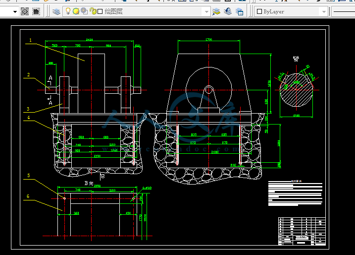
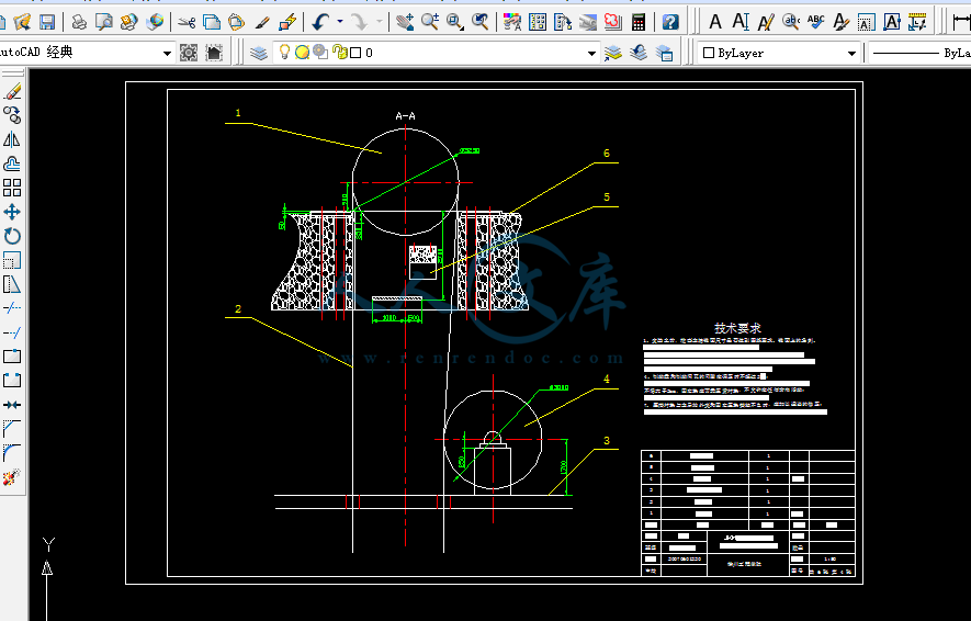

矿井提升机装配图A0.dwg
矿井提升机装配图A0.dwg

多绳摩擦式提升机的设计【6张图纸】【优秀】

收藏

压缩包内文档预览:
预览图
编号:420514    类型:共享资源    大小:1.83MB    格式:RAR    上传时间:2015-03-29 上传人:上*** IP属地:江苏
39
积分
关 键 词:
多绳 摩擦式 提升机 设计 图纸 多绳摩擦式 摩擦式提升机
资源描述:

多绳摩擦式提升机的设计

目录

摘要I

AbstractII

1 绪论1

2主井提升机的选型设计3

2.1 计算原始数据3

2.2 箕斗的选型3

2.3 提升钢丝绳的选择7

2.3.1钢丝绳的最大悬垂长度7

2.3.2 估算钢丝绳每米重力7

2.3.3 钢丝绳安全系数校核8

2.3.4 提升钢丝绳的维护和试验9

2.4 选择提升机10

2.5 提升机的维护与检修12

2.5.1 提升机设备的日常维护12

2.5.2 提升机设备的定期检查12

2.5.3 提升机设备的计划维修13

2.5.4 提升机的润滑14

2.5.5 主提升机操作工自检自修的具体内容15

2.6 提升系统的确定16

2.7 提升容器的最小自重17

2.8 预选电动机18

2.8.1 电动机转数18

2.8.2 提升机的最大速度18

2.8.3 预选电动机功率18

2.9 提升系统总变位质量19

2.9.1 变位重量19

2.9.2 变位质量19

3 提升设备的运动学和动力学20

3.1 提升速度图20

3.1.1 六阶段速度图20

3.1.2 加速度的确定21

3.2 提升能力校核25

3.3 电动机等效功率计算25

3.3.1 运动力计算25

3.3.2 等效力计算27

3.3.3 等效功率28

3.3.4 校核电动机过负载系数28

3.4 电耗计算28

4 提升机的防滑验算30

4.1 提升机的防滑验算30

4.1.1 静防滑安全系数31

4.1.2动防滑安全系数31

4.1.3 制动力矩的验算32

5 最终的确定方案33

结论34

致谢35

参考文献36

1 绪论

矿山提升机是矿山大型固定机械之一,矿山提升机从最初的蒸汽机拖动的单绳缠绕式提升机发展到今天的交——交变频直接拖动的多绳摩擦式提升机和双绳缠绕式提升机已经历了170多年的发展历史,它是矿山井下生产系统和地面工业广场相连接的枢纽,被喻为矿山运输的咽喉。因此矿山提升设备在矿山生产的全过程占有重要的地位。

我国早在公元前1100年左右就发明和使用了辘轳提水和提升重物,这就是现在提升机的始祖。1953年抚顺重型机器厂制造了我国第一台缠绕式提升机;1958年洛阳矿山机器厂制造了第一台多绳摩擦提升机。国外矿井提升机的发展有几个代表性的时期:1827年出现第一台蒸汽提升机;1877年制造了第一台单绳摩擦提升机;1905年使用了第一台电动提升机;1938年创造了第一台多绳摩擦提升机;1957年发明了多绳缠绕式提升机。

一个现代化的矿井在提升设备的选型上尤为重要。因为提升设备选型的合理与否,直接关系到矿井的安全和经济性,因此确定合理的提升系统时,必须经过多方面的技术经济比较,结合矿井的具体条件选择合适的设备。目前我国可以成批生产各种现代化大型矿井提升机以及各种配套设备,无论从设计、制造、自动控制等各方面,我国生产的矿井提升设备都正在跨入世界先进的行列。

根据矿井提升机工作原理和结构的不同,可分为缠绕式提升机和摩擦式提升机。单绳缠绕式提升机是较早出现的一种,它工作可靠,结构简单,但是仅适用于浅井及中等深度的矿井,而对于井深超过300米的矿井,宜选用多绳摩擦式提升机。在国内外,多绳摩擦式提升机飞跃发展,其发展速度远远超过单绳缠绕式提升机,这是因为它有着许多单绳缠绕式提升机无法比拟的优点,其优点如下:

提升容器及静荷载由多根钢丝绳共同承担,提升钢丝绳直径较小,主导轮直径及整个机器尺寸都相应缩小,设备重量也减轻了。

由于提升容器是同时悬吊在多根钢丝绳上,这些钢丝绳一般不会同时拉断,故可以不设置防坠器。

主导轮直径的缩小,系统的惯量和主轴上的扭力矩也随之减小,因而可以使用高速电动机和重量较轻的减速器,电动机功率和电能消耗都相应降低。

提升钢丝绳的根数是偶数,且由左向捻和右向捻各占一半组成,可以互相抵消钢丝绳运行中松捻的扭力,减轻了提升容器对罐道的运行阻力,因而延长了罐道及罐耳的使用寿命。

当多绳摩擦轮提升机安装在井塔上时,减少了工业广场的占地面积,并为地面生产系统的布置创造了有利条件。

下面是我针对不同的矿井的地质、煤层等情况,进行综合计算分析后,本着安全、经济等原则对提升设备系统进行的选型设计。

本设计充分贯彻以下设计原则:根据国家现有的设备生产状况,结合某些使用中的具体情况,以及经济角度出发尽量选用国产设备并力求在条件基本相当的情况下进行技术的方案比较,选择即经济又合理的设备。

由于本人水平有限,设计中难免出现错误和不足之处,敬请各位老师指正。

内容简介:
徐州工程学院毕业设计(外文翻译)Int J Adv Manuf Technol (2003) 21:604611 国际日报所有权和版权 先进的制造技术 2003 伦敦斯普林格出版社有限公司二级齿轮减速器的球手万向节的间隙计算J. H. Baek, Y. K. Kwak 和 S. H. Kim机械工程系,韩国先进的科学技术协会,373-1 Gusung-dong Yusung-gu Daejon,韩国一种用于计算有二级齿轮减速器的级数或边际贡献率的新技术被提出。这个概念是基于频率响应的变化特性,尤其是谐振频率和共振频率的变化,由于每个阶段的强烈变化不同,尽管二级齿轮减速系统总的强烈变化不变。技术的有效性在验证万向节得到了满意的结果。人们认为所提出的技术将使具有二级齿轮减速器的生产设备和系统的诊断和维修变得更高效经济合理。关键词:谐振频率;间隙计算;边际贡献率;频率响应特性;共振频率;球手万向节1. 摘要自动化生产设备和机器人的频繁使用极大的提高了对伺服系统和伺服电机的需求。随着电机制造技术的进步,伺服系统已经发展出不需要齿轮减速机的直接驱动类型电机。然而,迄今为止,齿轮减速机伺服系统被广泛国内外很多领域的生产设备,因为伺服系统的体积重量比齿轮减速机的大,而转矩相对比起来显得较小。有齿轮减速机的伺服系统从开始使用就对齿轮有间隙。因此,为处理这些问题做了很多研究。为了诊断和保持机器人和伺服系统的性能,研究开发了一种监测和检测强烈变化大小的方法。Dagalakis和Myers以相关函数和频率响应共振峰之间的大小和电机电压和机器人加速度为手段。Stein和Wang为了检测和计算有齿轮减速器的伺服系统的间隙,基于动量转移分析开发了一种技术。他们发现和第二齿轮相撞的主要齿轮的速度改变和间隙大小有关。Saker等人发展了一种技术补充Stein和Wang由于使用脉冲力矩的影响,而不是主要齿轮的速度变化。Pan等人发展了一种技术用于检测和分类使用WignerVille分派结合一个正弦联合运动和机器人加速度关联的二维相关函数。但是,还没有技术用于估计级数或控制通常用于生产设备和机器人的有多级齿轮减速器的伺服系统间隙每个阶段的速度。为了获得大小不同的间隙并使这种级数保持在正确的范围,知道系统每个阶段的间隙大小显得非常重要。因此,本文的目的是提出一种技术用于计算级数或控制有二级齿轮减速器的伺服系统的边际贡献率。边际贡献率被定义为第一阶段的间隙和总的间隙的大小比例。根据每个阶段的间隙和级数的变化,计算每个阶段的间隙的观念建立在频率响应特性伺服系统的谐振频率(ARE)和共振频率(RF)的改变,尽管总的间隙在伺服系统中是不变的。为了验证该方法的有效性,二个具有球手万向节的为了稳定方向的驾驶伺服系统用于实验。一个是方位驾驶伺服系统(ADSS),另一个是海拔驾驶伺服系统(EDSS),二个伺服系统都具有二级齿轮减速器。2. 球手万向节模型2.1 球手万向节里的ADSS模型本文中提到的,如图1(a)所示就是具有二级齿轮减速器的球手万向节的照片。ADSS和EDSS相当于球手万向节的二个驱动部分。图1 (a)球手万向节 (b)ADSS结构 (c)ADSS模型 (d)EDSS结构 (e)EDSS模型在图1(b)中所示,ADSS部分中,除了从动齿轮2固定在固定轴上,阴影部分如主动齿轮2,传动轴1,从动齿轮1,主动齿轮1,电动机和关于轴线AA对称的轴都在转动轴承上。这是假设由于负载,每一个支撑轴承都没有任何间隙。同时,忽视阻尼特性的影响。在这些假设的基础上提出了如图1(c)所示的ADSS模型。主动齿轮1的惯性转矩包括电动机在内。扭转弹簧代表从动齿轮1右边由于主动齿轮1和从动齿轮1的牙刚度造成的扭转刚度。轴1中,惯性转矩集中在从动齿轮1和主动齿轮2中间和扭转弹簧上,连接从动齿轮1和主动齿轮2的轴1相当于受到2倍扭转力。由于从动齿轮2和固定轴是固定的,所以他们只受到扭转力矩而没有受到惯性转矩。当主动齿轮固定时,每个间隙被描述成齿轮旋转角度。在图1(c)中由(双点)阴影线封闭的组件表明ADSS的负载。ADSS被认为由一个转数表过滤器一个电机放大器和上述结构组成。电机放大器用于放大电机的输入电压。一个具有转速表的永磁型直流电机作为一个执行机构。使用一个二阶低通滤波器是为了过滤转速表的输入电压。这些部件的电学量等式如下所示: 式(1) 式(2a) 式(2b) 式(3) 式(4)电动机的运动公式如下所示: 式(5)由于主动齿轮1和从动齿轮1之间的间隙,从动齿轮1的传递扭矩被描述成公式6。模型的不工作区域被用作间隙的模型。 式(6)其中 式(7)从动轮1的运动等式如下: 式(8)轴1的运动等式如下: 式(9)此外,主动轮2的运动等式如下: 式(10)图2 根据边际贡献率画出的ADSS的图表() (a)实例1 (b)实例2 (c)实例3 (d)实例4 (e)实例5 (Sim:模拟数据;Exp:实际数据)像式6一样,扭转负载的为式11所示: 式(11)其中 式(12)这里,从动轮和轴2之间的等效扭转刚度如下: 式(13)最后, 负载等式如下: 式(14)从这些等式中可以得出,经过过滤的转速表输出电压和经过电机放大器的输入电压相关。此外,总间隙和每个阶段的间隙的关系如下: 式(15)其中 (i=1,2) 式(16)2.2 球手万向节中的EDSS模型在这个部分,EDSS模型和运动等式是推导出来的。EDSS结构如图1(d)所示。由于从动轮2是直接连接到负载,这个时候从动轮2的转动惯量包括负载而从动轮2只有一个扭转弹簧模型,如图1(e)所示。EDSS的电机放大器和转速表过滤器这之间的运动等式和ADSS的一样,除了把运动等式(10)(13)和运动等式(15)更换成运动等式(17)(20),如下所示: 式(17) 式(18)其中 式(19) 式(20)从运动等式(1)(9),运动等式(14)到运动等式(17)(20),是反映转速过滤器的输出电压和电机放大器的输入电压的关系。3. 仿真众所周知,总间隙的增加会导致系统的频率响应特性,这会导致系统的有效扭转惯量减少,转速表过滤器的输出电压和电机放大器的输入电压的关系会发生改变。尽管总间隙大小是不变的,但是,这也没被报道,因为一个拥有每个阶段都不同的间隙的伺服系统会有不同的频率反映特性。在这个试验中,伺服系统中的每个阶段的间隙是通过这种现象和假设检验的。为了验证这个假设,ADSS的频率响应特性是根据边际贡献率研究的。如图2所示,ADSS的波特图是由模拟获得的。表1给出了用于模拟的规格。根据边际贡献率变化得出的每个阶段的间隙大小的组合在表2列出。他们是从运动公式(15)和运动公式(20)获得。为了得到图2的模拟结果,对上一节中的运动方程的描述被转换成一个图表。模拟结果就需要使用MATLAB Simulink V.6.1软件。由电机放大器提供的正弦电压的振幅峰值是2.5V,取样时间为10秒。图2中,由频率分析得到的波特图为了提取转速过滤器的输出电压和供给电机放大器的正弦电压组成的激振频率。由图3(a)得到的ARF和RF汇总在表2中。ARF和RF的不同如图3(b)所示。从图3(a)和图3(b)可以发现伺服系统的频率反映特性是根据每个阶段的间隙的大小的改变而改变,尽管总间隙大小不变。为了更深入的调查这种现象,球手万向节的EDSS和ADSS以相同的方式模拟。由图3(d)和图3(e)得到的结果列在表2。从图3(a),(b),(c)和(d)可以证实尽管总间隙的大小是不变的,但是由于具有二级齿轮减速器的伺服系统的每个阶段的间隙的大小变化,会有一个不同的频率响应特性。表1:ADSS和EDSS的参数参数ADSSEDSS从动齿轮1的齿数,5.946.41扭转强度,(mN/rad)3.40E44.74E4从动齿轮1的转动惯量,(kg)2.34E-53.69E-5轴1的扭转刚度,22.81.54E2轴1的惯性矩,8.30E-82.04E-7主动轮2的惯性矩,2.21E-74.84E-7齿轮齿数比,10.57.75等效扭转刚度,()7.74E42.54E5载荷的惯性矩,()2.75E-31.44E-2载荷静摩擦扭矩,()7.0E-37.1E-3总间隙,(deg。)0.0660.276电机电感,8.50E-4电机电阻,4.10Back-EMF常量,3.44E-2转矩灵敏度,3.49E-2续表1电机的惯性矩,8.60E-6电机的静摩擦力矩,1.40E-2电机放大器增益,4.11转速灵敏度,8.60E-2传递函数的低通滤波器,电机的阻尼系数,1.6E-4表2. 根据边际贡献率得到的ADSS和EDSS的仿真结果和实验结果(Exp:实验结果)4. 实验根据实验获得的ADSS和EDSS的波特图如图4(a)和图4(b)所示,是由动态分析仪(HP35670A)所获得的。由实验得到的ADSS和EDSS的ARF和RF如表2所示。为了验证该方法的准确度和有效性,把系统的每个齿轮减速器分解后,每个阶段的ADSS和EDSS的间隙通过光学显微镜测量得到。每个阶段的间隙的实例测量如图4(c)和(d)所示,测量数据列在表2.图3 根据边际贡献率得出的模拟结果 (a)ADSS的ARF和RF (b)ADSS的ARF和RF的不同之处 (c)ADSS的误差指数 (d)EDSS的ARF和RF (e)EDSS的ARF和RF的不同之处 (f)EDSS的误差指数5. 结果和讨论因为仿真的结果是在忽略阻尼效果和轴承速度的假设的情况下得到的,这导致在实验和仿真之间很难获得完全一致的结果。因此,仿真结果和实验结果的误差指数和被发现的最小边际贡献率被定义为等式(21)。误差率= 式(21)根据边际贡献率得到的ADSS和EDSS的误差率如图3(c)和(f)所示。研究表明ADSS的边际贡献率的最小误差率为25% ,EDSS的边际贡献率的最小误差率为0%。由每个阶段测量得到的ADSS和EDSS的边际贡献率为别为 23% 和4%。从图4(e)可以发现被提出的技术可以充分准确的估计大小或具有二级齿轮减速器的球手万向节的每个阶段的间隙的边际贡献率。图4 (a)ADSS的实验结果 (b)EDSS的实验结果 (c)ADSS的间隙测量 (d)EDSS的间隙测量 (e)估计的边际贡献率和实验得到的边际贡献率的比较比较图3(c)和图3(f),EDSS比ADSS有一个更高的最小误差指数(EDSS:20Hz,ADSS:10Hz)。人们认为最住要的误差来源于忽略阻尼特性的假设。对图1(c)和图1(e)的准确的传递函数的分析是非常复杂和难懂的。因此,为了简化阻尼特性的分析,每个伺服系统被简单的认为是一个具有二个量和一个模型的线性系统。从图4(a)和图4(b)看出,由等式9和10计算得到的近似阻尼因子和ARF和RF的频率减少比例。 式(22) 式(23) (当时) 式(24a) (当时) 式(24b) 阻尼因子和降频比例都是由图5(a)和图5(b)获得的。ADSS的ARF阻尼因子为0.075,ADSS的RF阻尼因子为0.083,而EDSS的ARF阻尼因子为0.135,EDSS的RF阻尼因子为0.246。ADSS的ARF频率降低比例为0.56%,ADSS的RF的频率降低比例为0.69%,而EDSS的ARF频率降低比例为1.8%,EDSS的RF频率降低比例为6.2%。从图5(a)和图5(b)可以看出,人们认为EDSS的误差大于ADSS的误差主要是由于阻尼系数,就像前者有更复杂的结构而后者根据负载。人们还认为剩余的误差来源于EDSS的负载的不确定性。最后,人们认为如果系统的负载有一个小的阻尼系数和小的不确定性,ARF和RF的频率特性可以用来估计具有二级齿轮减速器的球手万向节的每个阶段的间隙的大小和边际贡献率。 图5(a)ADSS和EDSS的阻尼因子(b)由于阻尼因子造成的ADSS和EDSS的频率减少比例6. 结论频率响应特性的ARF和RF被认为是为了估计具有二级减速齿轮器的球手万向节的每个阶段的间隙的大小和边际贡献率的措施。该方法的概念是基于由于每个阶段的间隙的大小的变化的引起的ARF和RF的变化,尽管间隙的总大小是保持不变的。仿真结果表明,如果伺服系统,尤其是,伺服系统负载,具有一个小的阻尼系数和一个小的不确定性,该技术能够分别估计具有二级齿轮减速器的ADSS和EDSS的每个阶段的间隙大小。该技术具有以下几个优势:第一,这是一种用于估计如果系统的间隙的总大小可以获得的系统的每个阶段的间隙的全新的方法。第二,该技术不需要外加的传感器如加速度计或扭距传感器,因为他可以测量使用转数计的电机的角速度。第三,由于只有一个松的或过度松的齿轮需要调整或替换而不是取代整个齿轮减速器,所以这种技术是高效和经济的。第四,这种技术可以应用到nonrobotic伺服系统,比如说NC机械,因为它是机器人链接上或者是一个伺服系统的输出抽上的一个不是必要的传感器。人们都认为采用这种技术,诊断和维护各种生产机械和各种伺服系统将会变得更高效更经济。致谢我们要特别感谢LG Innotek有限公司支持这个研究和Sung Min Hong, Ho Young Kim 和Byung HoLee 的赞助。符号 电机的粘滞阻尼系数() 衡量从动齿轮i的角侧隙()(i=1,2) 输出阶段测量的总间隙(),从试验中得到的在点附近的半功率点宽度频率(Hz), 从试验中得到的ARF和RF(Hz), 从模拟中得到的ARF和RF(Hz),仿真和实验中得到的ARF和RF的不同之处(Hz)转数表过滤器的传递函数 电机电流(A),从动齿轮1的惯性矩,负载的惯性矩,电机的惯性矩,传动轴1的惯性矩() 主动齿轮i的惯性矩()(i=1,2) 从动齿轮2和主动齿轮2之间的等效扭转刚度() 电机放大器的获得 E.m.f.常量 主动齿轮i和从动齿轮i之间的扭转刚度()(i=1,2) 第i根轴的抗扭劲度()(i=1,2) 电机的转矩灵敏度() 灵敏度转速() 电机的电感(H) 由于第i个从动齿轮和第i个主动齿轮之间的侧隙角的弧长(m)(i=1,2) 主动齿轮i和从动齿轮i的齿数比(i=1,2)主动齿轮2和从动齿轮2之间的回转齿数比() 阻尼因子的定义因素, 由于阻尼影响的ARF和RF的频率降低比例(%) 运动抗阻(), 电机负载的静摩擦扭矩() 从动齿轮1的传递扭矩() 负载扭矩()电机扭矩() 电机放大器的输入电压(V) 电机的输入电压(V) 转速计的输出电压(V) 转速过滤器的输出电压(V) 在从动齿轮旁边测量得到的角侧隙半值(rad)(i = 1, 2) 第i阶段的角传动误差(rad)(i = 1, 2),从动齿轮1的旋转角度,负载的旋转角度,电机的旋转角度,主动齿轮2的旋转角度,和传动轴1的旋转角度(rad), 谐振的阻尼因子和共振的阻尼因子Sign()括号内的sign值14Int J Adv Manuf Technol (2003) 21:604611Ownership and Copyright 2003 Springer-Verlag London LimitedBacklash Estimation of a Seeker Gimbal with Two-Stage GearReducersJ. H. Baek, Y. K. Kwak and S. H. KimDepartment of Mechanical Engineering, Korea Advanced Institute of Science and Technology, 373-1 Gusung-dong Yusung-gu Daejon,KoreaA novel technique for estimating the magnitude or contributionratio of each stage backlash in a system with a two-stage gearreducer is proposed. The concept is based on the change offrequency response characteristic, in particular, the change ofanti-resonant frequency and resonant frequency, due to thechange of the magnitude of the backlash of each stage, eventhough the total magnitude of the backlash of a system witha two-stage gear reducer is constant. The validity of thetechnique is verified in a seeker gimbal and satisfactory resultsare obtained. It is thought that the diagnosis and maintenanceof manufacturing machines and systems with two-stage gearreducers will become more efficient and economical by virtueof proposed technique.Keywords: Anti-resonantfrequency;Backlashestimation;Contribution ratio; Frequency response characteristic; Resonantfrequency; Seeker gimbal1.IntroductionThe automation of manufacturing machines and the frequentuse of robots and servo systems have greatly increased thedemand for servo systems with servomotors. With the advanceof motor manufacturing techniques, servo systems have beendeveloped with direct drive type motors that do not requiregear reducers. However, thus far, servo systems with gearreducers have been used extensively in manufacturing machinesin many fields, because the servo system volume and weightis larger than that of the gear reducer, while its torque isrelatively small in comparison.Servo systems with gear reducers have had problems relatedto gear backlash since their inception. Accordingly, manystudies have been performed in order to deal with the problems.Correspondence and offprint requests to: J. H. Baek, Research andDevelopment 7 Group, LG Innotek Co., Ltd., 1481 Mabuk-ri Gusung-eup Yongin-city Kyonggi-do, 449910, Korea.E-mail: jhbaekbReceived 5 February 2002Accepted 29 March 2002In order to diagnose and maintain the performance of therobots and servo systems, a method of monitoring and detectingthe magnitude and change of backlash has been developed.Dagalakis and Myers used a coherence function and the magni-tude of resonant peak in the frequency response between themotor voltage and the acceleration of a robot link as measures1. Stein and Wang developed a technique based on momen-tum transfer analysis in order to detect and estimate thebacklash of a servo system with a gear reducer. They foundthat the speed change of the primary gear due to impact withthe secondary gear is related to the magnitude of the backlash2. Saker et al. developed a technique to complement the workof Stein and Wang using the impulsive torque due to impact,instead of the speed change of the primary gear 3. Pan et al.developed a technique for detecting and classifying the backlashof a robot by using WignerVille distributions combined witha two-dimensional correlation of the relationship between thesinusoidal joint motion and the acceleration of the robot link4. However, there is no technique for estimating the magni-tude or contribution ratio of each stage of the backlash in aservo system with a multistage gear reducer, which is oftenused in manufacturing machines and robots. It is very importantto know the magnitude of each stage backlash of system inorder to obtain the desired magnitude of backlash and tomaintain that magnitude in a correct range. The purpose ofthis paper is, therefore, to present a technique for estimatingthe magnitude or contribution ratio of each stage backlash ofa servo system with a two-stage gear reducer. The contributionratio is defined as the ratio of the magnitude of the first stagebacklash to that of the total backlash. The concept for estimat-ing the magnitude of each stage backlash is based on thechange of anti-resonant frequency (ARF) and resonant fre-quency (RF) in the frequency response characteristic of a servosystem, according to the change of the magnitude of eachstage of backlash, even though the total backlash of the servosystem is constant. In order to verify the validity of theproposed technique, two driving servo systems of a seekergimbal, which are used in order to stabilise the orientation ofan object, are considered. One is an azimuth driving servosystem (ADSS); the other is an elevation driving servo system(EDSS). Both servo systems have two-stage gear reducers.Backlash Estimation of a Seeker Gimbal6052.Model of Seeker Gimbal2.1Model of the ADSS in the Seeker GimbalA photograph of the seeker gimbal with two-stage gear reducerswhich is considered in this paper is presented in Fig. 1(a).The ADSS and EDSS correspond to the two driving parts ofthe seeker gimbal. In the case of the ADSS, the hatchedcomponents, pinion 2, shaft 1, gear 1, pinion 1, motor andbearings rotate with respect to the AA? axis except that gear2 is attached on a fixed shaft as shown in Fig. 1(b). It isassumed that bearings support each shaft without any clearance,due to the preload. Also, the influence of the damping charac-teristic is neglected. The model of the ADSS obtained underthese assumptions is presented in Fig. 1(c). The moment ofFig. 1. (a) Seeker gimbal; (b) structure of ADSS; (c) model of ADSS; (d) structure of EDSS; (e) model of EDSS.inertia of pinion 1 is included with that of the motor. Thetorsion spring represented at the right side of gear 1 indicatesthe torsion stiffness due to tooth stiffness between pinion 1and gear 1. In the case of shaft 1, the moment of inertia islumped at the centre of the distance between gear 1 and pinion2 and torsion springs, with twice the value of torsion stiffnessof shaft 1, are connected with gear 1 and pinion 2. Becausethey are fixed, gear 2 and the fixed shaft are modelled so thatthey have only torsion springs without moment of inertia. Eachbacklash is represented as the angles of rotation of the gearswhen the pinions are fixed. Components enclosed by a phantom(double dot) line in Fig. 1(c) indicate the load of the ADSS.The ADSS considered consists of a tachometer filter, a motoramplifier and the aforementioned structure. The motor amplifieris used to amplify the input voltage of motor. A permanent606J. H. Baek et al.magnetic field type d.c. motor with a tachometer is used asan actuator. In order to filter the output voltage of the tach-ometer, a second-order low-pass filter is used. The governingelectric Eq. of these components are as follows 5:Vm= kaVi(1)Ladiadt+ Rmia+ kb?m= Vm(2a)Tm= ktia(2b)Vt= kts?m(3)Vo(s) = Gf(s)Vt(s)(4)The Eq. of motion for the motor is as follows:Jm?m+ Bm?m= Tm?Tg1N1? Tf,msign (?m)(5)The torque transmitted to gear 1 is represented as a nonlinearEq., presented in Eq. (6), due to the backlash between pinionFig. 2. The bode diagram (Vo/Vi) of ADSS according to contribution ratio: (a) case 1; (b) case 2; (c) case 3; (d) case 4; (e) case 5. (Sim:simulation; Exp: experiment.).1 and gear 1. The model of the dead zone is used as themodel of the backlash 6.Tg1=?kg1(?d1?1),?d1?10,?d1?1kg1(?d1+?1),?d1?1?(6)where?d1=?m/N1?g1(7)The Eq. of motion for gear 1 is as follows:Jg1?g1= Tg1? 2ks1(?g1?s1)(8)The Eq. of motion for shaft 1 is as follows:Js1?s1= 2ks1(?g1+?p2) ? 4ks1?s1(9)Besides, the equation of motion for pinion 2 is as follows:Jp2?p2= 2ks1(?s1?p2) ?1NrTL(10)Backlash Estimation of a Seeker Gimbal607The torque of the load is represented in Eq. (11), like Eq. (6).TL=?k2(?d2?2),?d2?20,|?d2|?2k2(?d2+?2),?d2?2?(11)where?d2=?p2/Nr?L(12)Here, the equivalent torsion stiffness between gear 2 and shaft2 is as follows 7:k2=kg2ks2kg2+ ks2(13)Finally, the equation of motion for the load is as follows:JL?L= TL? Tf,Lsign (?L)(14)The response of the output voltage of the tachometer filterwith respect to the input voltage of the motor amplifier isobtained from these Eq. In addition, the relation between thetotal backlash and each stage backlash is as follows:bt= b2+1Nrb1(15)wherebi= 360 ?i/?(i = 1,2)(16)2.2Model of the EDSS in the Seeker GimbalIn this subsection, the EDSS models and Eq. of motion arederived. The structure of the EDSS is presented in Fig. 1(d).Because gear 2 is directly attached to the load, the momentof inertia of gear 2 is included with that of the load and gear2 has only a torsion spring model, as shown in Fig. 1(e). TheEq. of motion for the EDSS between the motor amplifier andtachometer filter are the same as those of the ADSS, exceptfor replacing Eqs (10)(13) and Eq. (15) with Eqs (17)(20)as follows:Jp2?p2= 2ks1(?s1?p2) ?1N2TL(17)TL=?kg2(?d2?2),?d2?20,|?d2|?2kg2(?d2+?2),?d2?2?(18)where?d2=?p2/N2?L(19)bt= b2+1N2b1(20)From Eqs (1)(9), Eq. (14) and Eqs (17)(20), the responseof the output voltage of the tachometer filter with respect tothe input voltage of the motor amplifier is obtained.3.SimulationIt is well known that an increase in the total backlash in asystem causes the frequency response characteristic, of theoutput voltage of the tachometer filter with respect to the inputvoltage of the motor amplifier, to change because it reducesthe effective equivalent torsional stiffness of the system 8.However, it has not been reported yet that although the totalbacklash magnitude is constant, a servo system with a differentbacklash magnitude at each stage has different frequencyresponse characteristic. In this work, each stage of backlashof a servo system is examined by this phenomenon and hypoth-esis. In order to verify this hypothesis, the frequency responsecharacteristic of ADSS is investigated according to the contri-bution ratio. The bode diagrams of ADSS obtained from thesimulation are represented in Fig. 2. The specifications usedfor the simulation are presented in Table 1. The combinationsof the magnitude of backlash of each stage obtained accordingto the change of contribution ratio are listed in Table 2. Theyare obtained from Eqs (15) and (20). In order to obtain thesimulation results of Fig. 2, the equation of motion outlinedin the previous section are converted into a block diagram.The simulation is then performed using MATLAB SimulinkV. 6.1 software. The peak amplitude of the sinusoidal voltagesupplied to the motor amplifier is 2.5 V and the sampling timeused is 10 ?sec. Bode diagrams of Fig. 2 are made fromthe frequency analysis to extract only the excited frequencycomponent from the output voltage of the tachometer filterwith respect to the sinusoidal voltage supplied to the motoramplifier. The ARF and RF obtained are summarised in Table2 and are represented in Fig. 3(a). The difference between theARF and RF is shown in Fig. 3(b). From Fig. 3(a) and (b),it is found that the frequency response characteristic of a servoTable 1. Specifications for ADSS and EDSS.ParameterADSSEDSSGear ratio 1, N15.946.41Torsion stiffness, kg1(m ? N/rad)3.40E4 4.74E4Moment of inertia of gear 1, Jg1(kg ? m2)2.34E-5 3.69E-5Torsion stiffness of shaft 1, ks1(m ? N/rad)22.81.54E2Moment of inertia of shaft 1, Js1(kg ? m2)8.30E-8 2.04E-7Moment of inertia of pinion 2, Jp2(kg ? m2)2.21E-7 4.84E-7Gear ratio, Nr,N210.57.75Equivalent torsion stiffness, k2,kg2(m ? N/rad)7.74E4 2.54E5Moment of inertia of load, JL(kg ? m2)2.75E-3 1.44E-2Static friction torque of load, Tf,L(m ? N)7.0E-37.1E-3Total backlash, bt(deg.)0.0660.276Motor inductance, La(H)8.50E-4Motor resistance, Rm(?)4.10Back-EMF const., kb(V ? s/rad)3.44E-2Torque sensitivity, kt(m ? N/A)3.49E-2Moment of inertia of motor, Jm(kg ? m2)8.60E-6Static friction torque of motor, Tf,m(m ? N)1.40E-2Gain of motor amplifier, ka4.11Tachometer sensitivity, kts(V ? s/rad)8.60E-2Transfer function of low-pass filter, Gf(s)723439s2+ 1710s + 723439Viscous damping coeff. of motor, Bm(m ?1.6E-4N/(rad/s)608J. H. Baek et al.Table 2. The simulation result and experiment result of ADSS andEDSS according to the contribution ratio (Exp: experiment).Case Contribution b1b2Anti-Resonantratio (%)resonant(dB/Hz)(dB/Hz)ADSS1000.066?33.6/125?12.8/1272250.1730.0495?33.5/131?14.3/1353500.3470.0330?33.3/134?14.0/1454750.5190.0166?32.2/137?9.6/14951000.6930?30.8/1410.2/153Exp. 230.1610.051?22.3/128?18.6/137EDSS1000.276?24.7/50?3.4/792250.5350.207?23.7/51?15.1/843501.070.138?27.5/52?3.2/974751.600.069?20.8/52?5.9/9251002.140?22.4/51?3.9/89Exp. 40.08560.265?14.6/40?1.8/75Fig. 3. The simulation results according to contribution ratio: (a) ARF and RF of ADSS; (b) difference between ARF and RF of ADSS; (c)error index of ADSS; (d) ARF and RF of EDSS; (e) difference between ARF and RF of EDSS; (f) error index of EDSS.system is changed according to the change of the magnitudeof the backlash of each stage in spite of having the same totalbacklash. In order to investigate this phenomenon once more,the EDSS of the seeker gimbal is simulated in same manneras the ADSS. The results obtained are presented in Fig. 3(d)and (e), and listed in Table 2. From Fig. 3(a), (b), (d), and(e), it is confirmed that although the magnitude of the totalbacklash is constant, a servo system with a two-stage gearreducer has a different frequency response characteristic accord-ing to the change of the magnitude of the backlash of eachstage.4.ExperimentsTo obtain experimental bode diagrams of the ADSS and EDSS,a dynamic analyser (HP35670A) is used and the bode diagramsobtained are represented in Fig. 4(a) and (b). The ARF andBacklash Estimation of a Seeker Gimbal609RF of the ADSS and EDSS obtained from the experimentsare presented in Table 2. In order to verify the accuracy andvalidity of the proposed technique, the backlash of each stageof the ADSS and EDSS is measured using an optical micro-scope, after disassembly of each gear reducer from the systems.Measurement examples of the backlash of each stage arerepresented in Fig. 4(c) and (d) and the measured data arelisted in Table 2.5.Results and DiscussionBecause the simulation results are obtained under the assump-tions that ignore damping effects and bearing clearances, it isdifficult to obtain exactly consistent results between the experi-Fig. 4. (a) Experiment result of ADSS; (b) experiment result of EDSS; (c) backlash measurement of ADSS; (d) backlash measurement of EDSS;(e) the comparison of the estimated contribution ratio with the measured contribution ratio.ment and the simulation. Thus, the error index between thesimulation results and the experiment results is defined as Eq.(21), and the minimum contribution ratio is found.error index =|fAR,S? fAR,E|+|fR,S? fR,E|+|fD,S(21)? fD,E|The error indices of the ADSS and EDSS, according to thecontribution ratio, are represented in Fig. 3(c) and (f). It isshown that the contribution ratio having the minimum errorindex for the ADSS is 25% and that for the EDSS is 0%.The contribution ratios of the ADSS and EDSS obtained fromthe measurement of each stage backlash are 23% and 4%,respectively. From Fig. 4(e), it is also found that the proposedtechnique is sufficiently accurate to estimate the magnitude orcontribution ratio of the backlash of each stage of a seekergimbal with two-stage gear reducers.610J. H. Baek et al.Comparing Fig. 3(c) with Fig. 3(f), the EDSS has a muchhigher minimum error index than the ADSS (EDSS: 20 Hz,ADSS: 10 Hz). It is thought that the dominant error originatesfrom the assumption of neglecting the damping characteristic.The exact transfer function analysis of the model in Fig. 1(c)and (e) is very complex and complicated. Therefore, in orderto simplify the analysis of the damping characteristic, eachservo system is considered simply as a linear system with twomasses and one spring model 9. From Fig. 4(a) and (b), theapproximated damping factors are obtained and the frequencyreduction ratios of the ARF and RF are calculated using thefollowing Eq. 9,10?AR=12QAR=(f2,E? f1,E)2fAR,E(22)?R=fR,EfAR,E?AR(23)RAR= 1 ?1 ? 2?2AR(when 0?AR?0.707)(24a)RR= 1 ?1 ? 2?2R(when 0?R?0.707)(24b)The damping factors and frequency reduction ratios obtainedare represented in Fig. 5(a) and (b). The damping factors ofthe ADSS are 0.075 at the ARF and 0.083 at the RF, whilethose of the EDSS are 0.135 at the ARF and 0.246 at the RF,Fig. 5. (a) Damping factor of ADSS and EDSS. (b) The frequencyreduction ratio of ADSS and EDSS due to damping factor.respectively. The frequency reduction ratios of the ADSS are0.56% at the ARF and 0.69% at the RF, while those of theEDSS are 1.8% at the ARF and 6.2% at the RF, respectively.From Fig. 5(a) and (b), it is thought that the error of theEDSS is larger than that of the ADSS mainly because of thedamping factor, as the former has a more complicated structurethan the latter in terms of load. It is also thought that theremainder of the error arises from the uncertainty of the loadof the EDSS. Finally, it is thought that the ARF and RF inthe frequency response characteristic can be used to estimatethe magnitude or contribution ratio of the backlash of eachstage of a seeker gimbal with two-stage gear reducers if itsload has a small damping coefficient and small uncertainty.6.ConclusionsThe ARF and RF of the frequency response characteristic areconsidered as measures in order to estimate the magnitude orthe contribution ratio of the backlash of each stage of aseeker gimbal with two-stage gear reducers. The concept ofthe proposed technique is based on changes of the ARF andRF according to the change of the magnitude of the backlashof each stage, even though the total magnitude of the backlashis constant. It is verified that the technique can estimate eachstage backlash of the ADSS and EDSS with two-stage gearreducers, respectively, if the servo system, in particular, theservo system load, has a small damping coefficient and smalluncertainty. The technique has several advantages as follows:first, it is a novel method in that it estimates the backlash ofeach stage if the total magnitude of the backlash of servosystem is available. Second, the technique does not require anadditional sensor such as an accelerometer or torque sensor,because it measures the angular velocity of the motor usingthe tachometer. Third, it is efficient and economical becauseonly a loose or an excessively loose gear stage needs to beadjusted or replaced rather than having to replace the wholegear reducer. Fourth, it can be applied to nonrobotic servosystems such as NC machines because it is unnecessary toattach a sensor on the link of robot or the output shaft of aservo system 2. It is thought that using the proposed tech-nique, the diagnosis and maintenance of various manufacturingmachines and many servo systems will become more efficientand economical.AcknowledgementsWe would like to thank LG Innotek Co. for supporting thisstudy and Sung Min Hong, Ho Young Kim and Byung HoLee for their assistance.References1. N. G. Dagalakis and D. R. Myers, “A Technique for the detectionof robot joint gear tightness”, Journal of Robotic Systems, 2(4),pp. 414423, 1985.2. J. L. Stein and C. H. Wang, “Estimation of gear backlash:theory and simulation”, ASME Journal of Dynamic Systems,Measurement and Control, 120, pp. 7482, 1998.Backlash Estimation of a Seeker Gimbal6113. N. Sakar, R. E. Ellis and T. N. Moore, “Backlash detection ingeared mechanisms: modeling, simulation, and experimentation”,Mechanical Systems and Signal Processing, 11(3), pp. 391408,1997.4. M. C. Pan, H. V.
温馨提示:
1: 本站所有资源如无特殊说明,都需要本地电脑安装OFFICE2007和PDF阅读器。图纸软件为CAD,CAXA,PROE,UG,SolidWorks等.压缩文件请下载最新的WinRAR软件解压。
2: 本站的文档不包含任何第三方提供的附件图纸等,如果需要附件,请联系上传者。文件的所有权益归上传用户所有。
3.本站RAR压缩包中若带图纸,网页内容里面会有图纸预览,若没有图纸预览就没有图纸。
4. 未经权益所有人同意不得将文件中的内容挪作商业或盈利用途。
5. 人人文库网仅提供信息存储空间,仅对用户上传内容的表现方式做保护处理,对用户上传分享的文档内容本身不做任何修改或编辑,并不能对任何下载内容负责。
6. 下载文件中如有侵权或不适当内容,请与我们联系,我们立即纠正。
7. 本站不保证下载资源的准确性、安全性和完整性, 同时也不承担用户因使用这些下载资源对自己和他人造成任何形式的伤害或损失。
提示  人人文库网所有资源均是用户自行上传分享,仅供网友学习交流,未经上传用户书面授权,请勿作他用。
关于本文
本文标题:多绳摩擦式提升机的设计【6张图纸】【优秀】
链接地址:https://www.renrendoc.com/p-420514.html

官方联系方式

2:不支持迅雷下载,请使用浏览器下载   
3:不支持QQ浏览器下载,请用其他浏览器   
4:下载后的文档和图纸-无水印   
5:文档经过压缩,下载后原文更清晰   
关于我们 - 网站声明 - 网站地图 - 资源地图 - 友情链接 - 网站客服 - 联系我们

网站客服QQ:2881952447     

copyright@ 2020-2024  renrendoc.com 人人文库版权所有   联系电话:400-852-1180

备案号:蜀ICP备2022000484号-2       经营许可证: 川B2-20220663       公网安备川公网安备: 51019002004831号

本站为文档C2C交易模式,即用户上传的文档直接被用户下载,本站只是中间服务平台,本站所有文档下载所得的收益归上传人(含作者)所有。人人文库网仅提供信息存储空间,仅对用户上传内容的表现方式做保护处理,对上载内容本身不做任何修改或编辑。若文档所含内容侵犯了您的版权或隐私,请立即通知人人文库网,我们立即给予删除!