


版权说明:本文档由用户提供并上传,收益归属内容提供方,若内容存在侵权,请进行举报或认领
文档简介
1、always adopts mechanical tinplate to measure. There are some shortcomings that the measurement precision falls with machine abrasion, single time period setting and strong manpower 2. In this paper, we propose a novel multi-rate three-phase watt-hour meter based on AT89LV52. This multi-rate three-ph
2、ase watt-hour meter adopts AD7752 for measurement. It has the characteristics which are time-sharing measurement, accurate measurement, LCD display, automatic meter reading, flexible time period setting, timely emendation, low cost and novel design.II. STRUCTURE AND WORKING PRINCIPLEThe novel multi-
3、rate three-phase watt-hour meter proposed in this paper is based upon AT89LV52 singlechip 3. AT89LV52 has the flash memorizer with 8k bytes, cryptographical program memorizer with third class, RAM with 256 bytes, 32 programmable I/O lines, three time/ counter with 16 bits and a two class halt with s
4、ix vectors. The interface circuit adopts I2C bus unit which is a 8 bits singlechip with good performance and suitable price. The system structure diagram is shown in figure 1.Figure 1. System structure diagramThe principle of this multi-rate watt-hour meter is reading in themulti-rate time segments
5、using RS485 bus and noting in X25045 then take over correctional clock with RS485 bus and write in clock CMOS chip S3530A. The three-phase AC voltage and electric current pass through potentiometer and mutual inductance instrument respectively so as to produce small signal which is sent to AD7752 to
6、 complete measurement. The clock CMOS chip S3530A gives clock information per second in the course of automatic move and analyze this clock belongs to which period of time according to advance periods of time set in X25045 then save the electrical energy in RAM memorizeraccording to corresponding pe
7、riod of time. We write it to corresponding address of X25045 when the electrical energy achieves one degree in order to make the multi-rate measurement come true. This watt-hour meter hasfunctions of clear LCD display, missing phase detection, burthen control, halt electricity check and storage, aut
8、omatic meter reading and so on.III. THE DESIGH OF HARDWARE CIRCUITA Electrical energy measurementThe three-phase electrical energy measurement is realized by the low consume CMOS chip AD7752 of ADI company. The inside of AD7752 adopts digital circuit besides ADC, filter and multiplication circuit wh
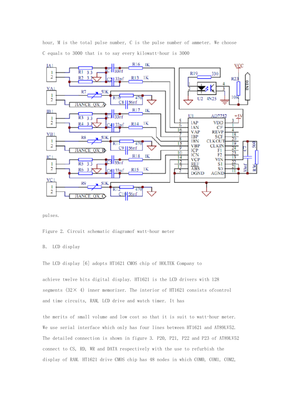
9、ich can eliminate noises effectively. The sampling course of voltage and electric current in three-phase AC power supply loop is shown in figure 2 in which IA stands for voltage sampling of A phase. The sampling circuits of B phase and C phase are similar to A phase. The power after integral is tran
10、sformed to electrical pulse for output. The pulse of fan-out CF enters intointerregnum INT0 of AT89LV52 through photoelectricity insulation 4N25. CPU measures the electrical energy 4. We adjust the pulse number of CF by combining the state of S1 and S2. The connection of electrical energy and pulse
11、is W = M C . In which, W is the electrical energy with the unit of kilowatt-hour, M is the total pulse number, C is the pulse number of ammeter. We choose C equals to 3000 that is to say every kilowatt-hour is 3000pulses.Figure 2. Circuit schematic diagramof watt-hour meterB LCD displayThe LCD displ
12、ay 6 adopts HT1621 CMOS chip of HOLTEK Company toachieve twelve bits digital display. HT1621 is the LCD drivers with 128 segments (32× 4) inner memorizer. The interior of HT1621 consists ofcontrol and time circuits, RAM, LCD drive and watch timer. It hasthe merits of small volume and low cost s
13、o that it is suit to watt-hour meter. We use serial interface which only has four lines between HT1621 and AT89LV52. The detailed connection is shown in figure 3. P20, P21, P22 and P23 of AT89LV52 connect to CS, RD, WR and DATA respectively with the use to refurbish the display of RAM. HT1621 drive
14、CMOS chip has 48 nodes in which COM0, COM1, COM2, COM3 connect to the communal end and drive output of LCD and SG0, SG1, SG2, SG3 connect to drive output of every segment respectively. In addition, an adjustable resistance of 20k is put between VDD and VLCD to adjust the display contrast of LCD. Exp
15、eriment shows that the contrast is better with VDD=5V and VLCD=4V.C Serial memorizerSerial memorizer adopts low power consumption chip X25045 of XICORcompany .It has three functions which are watchdog timer WTD, voltage supervision and serial memorizer E2PROM with 512 bytes. WTD can be set 200ms, 60
16、0ms and 1400ms time intervals. The software program is read into X25045. During the normal running of program, WTD receives the trigger signal in time intervals in order to ensure the normal running of program. X25045 will output a high potential through RESET line if WTD does not receive trigger si
17、gnal in time intervals. The trigger watt-hour meter reset in order to prevent program flying away. As the serial memorizer chip, 512 bytes of X25045 are used to storage the watt-hour meter code, multi-rate periods of time, the apex electricity, smooth electricity, vale electricity and total electric
18、ity of last month and this month. Storage can be divided into two same areas. One is used as data storage. The other is used for backup. The number of storage can be revised 100,000 times. Data can be stored for 100 years. It is connected with AT89LV52 by SPI agreement bus. The connection is shown i
19、n figure 3.D Clock circuitThe clock circuit is completed by S3530A chip. It is a low powerconsumption clock chip that supports I2C Bus. It sets the clock and calendar according to the data received by CUP communicating with RS485. At the same time, it continues to walk time by its own oscillation. T
20、he crystaloscillator of 32.768 kHz is put between Xin and Xout of S3530A which is connected with CPU through latching. SDA foot and SCL foot connect to P1.6 and P1.7 of AT89LV52 respectively. There are two interrupt alarming foots can be set as second output or minute output synchronizing pulse whic
21、h supply interrupt signal to AT89LV52 with one second period. Single-chip system will readout the current time through I2C communication interface according to this signal and calculate the period of time that this moment belongs to so as to realize the electrical energy measurement in different per
22、iods of time 5. This clock circuit has spare lithium battery. The powersupply VCC supply power in normal wiring and electrified for lithium battery of 3.6V. When there is power off, the system will automatically convert lithium battery to clock circuit for power supply. The clock will still running
23、accurately even the power is off.Figure 3. Partial circuit figure of watt-hour meterE RS485 CommunicationMAX485 chip can implement RS485 communication control ofmulti-rate watt-hour meter. MAX485 chip has RS485 communication protocol. It can take 128 hypogenous computers. Its transmission distance i
24、s greater than 1km and its transfer rate is up to 250kb per second. The watt-hour meter connects with the unit controller through the RS485 bus. Each unit has a cell controller can manage 128 multi-rate watt-hour meter. The cell controller connects to power management computer. Each watt-hour meter
25、has one and only meter number with eight bits of hex. The electrician should write the users information and meter number and then import to the power management computer for initial installation so ad to complete the connection of user and management computer. Management computer sends setting of p
26、eriod of time and clock information with the manner of broadcast communication without address information. PC uploads information by the way of calling address.F Lack Phase detection and relay controlIt can achieve relay control 7 with P27 of AT89LV52. P27 cancontrol relays using 4N25 photoelectric
27、ity isolator so as to complete powersupply and power control. Lack Phase detection gets the signal from fan-out of the relay and connects to 1 foot of photoelectricity isolator after passing a 75K resistance, the diode half-wave rectifier and capacitive filtering respectively. We detect the 4 foot o
28、f isolator to determine whether there is the lack of phase. If there is lack of phase, we detect again after 2 seconds overtime. We break off the power immediately if there is lack of power after the twice confirmation. In power protection circuit, it uses the INT1 interrupt foot of AT89LV52 to dete
29、ct signal.When there is a sudden power off, INT1 jumps into a low voltage and the INT1 interrupt enters to the power protection program relying on the energy storage capacitor to save data. In the system, pulse output of AD7752, relay control port and the inputs of lack phase detection all use photo
30、electric isolator 4N25. It sends electrical signal by light coupling which can enhance the ability of anti-jamming.IV. THE DESIGN OF SOFTWAREAThe distribution of resourceThe software program includes main program, X25045 read and write program, RS485 serial communication program, interrupt serve pro
31、gram, timer handling program, HT1621 display control program, electrical energy measurement in different period of time and power down protection program, and system self-checking and anti-interference handling program. Interrupt resource distribution of system is: INT0 interrupt is used as AD7752 p
32、ulse measurement, INT1 as synchronization detecting, timer T0 as 100 ms timing, T1 as 1ms timing, and T2 as baud rate generator for serial communication program. RS485 asynchronous communication is set to receiveinterrupt and check information for sending.B Module desighThe flow chart of main progra
33、m is shown in figure 4. The watt-hourmeter should be able to initialize at each power up time. The initializing program includes setting working mode of timers, serial stomata and interrupts for AT89LV52, writing control word into X25045, S3530A and HT1621. This system sets three periods of time. Th
34、e singlechip reads clock value from S3530A per second then analyze this clock belongs to which period of time according to advance periods of time set in X25045 then save the electrical energy in RAM memorizer according to corresponding period of time. We write it to corresponding address of X25045
35、when the electrical energy achieves one degree. The LCD display with 16 bits shows period of time and electrical energy information in turn. Figure 4. Flow chart of main programV. TESTING RESULTError measurement and running test have been made in Zibo Billion Electron Co., Ltd. The epigenous compute
36、r completes the setting of time management. There are three-rate period of time. The first period of time is vale electricity from 00 point 00 minute to 06 point 30 minutes. The second period of time is apex electricity from 06 point 30 minutes to 22 point 30 minutes. The third period of time is smo
37、oth electricity from 22 point 30 minutes to 24 point 00 minute. The setting of rate period of time is sent to computer management system by electric power company according to national policy and saved in X25045. The apex electricity, smooth electricity, vale electricity and total electricity per mo
38、nth read saved in electrical energy meter and sent to epigenous computer through cell controller. The communication baud rate is 9600 bits per second. The checkout platform of 0.1 grade standard electronic power meter is used as standard meter and the multi-rate watt-hour meter is the tested meter.
39、Billion Electron Company has carried out testing according to different load running. The measured data is shown in table 1 with the burthen of 30kW.TABLE I. COMPARE OF NORMAL METER AND TESTING METERThe testing result indicates that the error of this multi-ratewatt-hour meter is less than 1%, belong
40、s to 1.0 grade. The return reading of electrical energy is precision and the emendation of time is timely and right. By testing, the method of decreasing errors for electricity metering can be obtained. Firstly, adjust the sampling resistance of AD7752 to accurate value. Secondly, the value of this
41、resistance is needed less varying with temperature. Thirdly, during electricity metering progress, when mantissa portion of electricity is less than 0.01, the remaining pulse should be accessed together, thus cumulative error caused by lack of 0.01degree energy loss could be avoided.VI. CONCLUSION A
42、ND EXPECTATIONThe multi-rate watt-hour meter achieves electrical energycomputation in different time according to different time setting. It adopts RS485 for serial communication and realizes automatic meter reading and real-time emendation. The results of production in Billion Electron Company show
43、that the multi-rate three-phase watt-hour meter proposed in this paper has the characteristics of novel design technique, accurate measurement, and flexible time period setting. Various technical indexes achieve the technique standard for national intelligent card watt-hour meter. Therefore, it has
44、wide application.REFERENCES1 Bu Zhengliang, Yin Xianggen, Tu Guangyu. “Development of HV Watt-hour meter.” Automation of Electric Power Systems, 2006, 30(19): 89-93.2 Kosukegawa M., Sakumoto Y. “Traceability system of electric energy standard and tendency in static watthour meter development in Japa
45、n.” Sixth International Conference on Metering Apparatus and Tariffs for Electricity Supply, 1990,4: 259-263.3 Xuehai Li. Applied tutorial of singlechip. Electronic industry publishing company, 2003.4 Al-Khateeb Tarik, Blundel Martin. “An electronic meter for measuring the saving in electrical power
46、.” The Ninth Arab International Conference on Solar Energy (AICSE-9), Kingdom of Bahrain, 2007,4 (209):328-333.5 Liu Ying, Liu Qingyu. “Development of a self-calibration precision electrical measuring meter.” Proceedings of the 1998 Conference Precision Electromagnetic Measurements, 1998,7:276.6 Gao
47、 Yun-Peng, Teng Zhao-Sheng, Liu Peng. “Design of three-phase multi-functional harmonic energy meter.” Journal of Hunan University Natural Sciences, 2008, 35(9): 53-57.7 Qu Qingchang. “Key technology to three-phase electric meter and high voltage electric power measurement.” Acta Metrologica Sinica,
48、2007, vol28: 25-30.一种基于单片机的新型三相多费率电能表的设计Jishun Jiang Lanlan YuSchool of Electric and Electronic Engineering School of Electric and Electronic Engineering Shandong University of Technology Shandong University of Technology Zibo, 255091, China Zibo, 255091, China摘要:随着社会的发展,对电力的需求变得越来越大。在不同时间的电力不平衡现象日益
49、严重。为了合理调整电力负荷,节约能源,我们提出了一个新的多速率设计三相电度表。这种新型多速率三相电度表的设计原理是在AT89LV5基础上提出的。硬件和软件流程设计,以及实验数据的分析,详细介绍。通过审判淄博亿电子有限公司制造,它表明这种多速率三相电度表具有特色,是步行的精度,准确测量,自动抄表,灵活的时间设置,成本低。因此,这种新型三相多费率电度表具有广阔的应用前景。关键词:多速率,三相电度表,AT89LV52一.引言计算机技术的发展和应用推动了电表的智能化转型。由于电力的需求增大,在不同时间的电力需求不平衡的现象越来越严重,电力公司鼓励人们使用复费率电度表1,以合理调整电力负荷,节省能源。传
50、统的复费率电度表总是采用机械马口铁来衡量。也有一些不足之处,测量精度低与机械磨损快,单一的时间内设置需要强大的人力资源2。在本文中,我们在AT89LV52的基础上提出一个新的多速率三相电度表。这种多速率三相电度表采用测量AD7752。它的特点是分时计量,计量准确,液晶显示直观器,自动抄表,灵活的时间设置,及时校正,成本低,设计新颖。二.结构和工作原理本文提出的新颖的多速率三相电度表是基于AT89LV52单片机3。 AT89LV52具有8K字节,三级加密程序存储器,256字节的RAM,32个可编程I / O线,3次/ 16位和一个6向量2级停止计数器的RAM。该接口电路采用I2C总线的单位,是一
51、个8位具有良好的性能和价格合适的单片机。该系统结构图见图1。图1。系统结构图这种多费率电度表读数的原则是多速率一次使用RS485总线段并记录在X25045然后接管RS485总线时钟并将该时钟写入CMOS芯片S3530A。三相交流电压和电流通过电位仪和互感分别以生产小信号,传送到AD7752完成测量。时钟芯片S3530A提供了时钟的自动移动过程中每秒的信息和分析这种时钟属于哪个时期根据预先设定的时间在X25045的时间然后保存在RAM存储器电能按照相应的时间期限。我们把它写的X25045的通讯地址,当电能达到1度,以使多速率测量成真。这种电度表具有明确的液晶显示功能,缺相检测,负荷控制,停止用电
52、检查和存储,自动抄表等三系统硬件电路的设计A 电能计量三相电能计量由ADI公司的低耗能CMOS芯片AD7752来实现了。在AD7752内部,除了采用的ADC,滤波器和乘法电路,还有可以有效地消除噪声的数字电路。采样过程中的电压和电流的三相交流电源回路如图2所示,其中IA代表A相电压采样。对B相和C相的取样电路类似A相。电源积分后转化为电脉冲输出。脉冲从CF口通过光电绝缘4N25进入到空位的AT89LV52的INT0。 CPU测量电能4。我们通过S1和S2的联系调节CF的脉冲数。电力能源和脉冲的转换关系是W = MC的。其中,W是同千瓦时电能的单位,M是总脉冲数,C是电表脉冲数。我们选择C=30
53、00即每千瓦小时,每千瓦时 3000脉冲。图2。电度表的电路原理图B 液晶显示器该液晶显示器6通过盛群公司的CMOS芯片对HT1621的实现12位数字显示。HT1621是128段(32 × 4)内部存储器,LCD驱动器。在HT1621内部由控制电路和时间,内存,液晶驱动器和计时器。它有体积小,成本低的优点,使其使用于电度表。我们使用串行接口,在HT1621和AT89LV52之间只有4条线。详细的连接如图3所示。AT89LV52的P20,P21,P22,P23分别连接到CS,RD,WR并分别与数据使用翻新的RAM显示。对HT1621驱动器芯片已在48个节点的COM0,串口COM1,CO
54、M2端口,COM3连接到公共端和驱动器的LCD和SG0,的SG1,SG2的,SG3连接到驱动器输出的每个部分分别输出。此外,一个20k的电阻可调之间放置VDD和VLCD来调整液晶显示对比度。实验表明,VDD= 5V比VLCD= 4V的更好。C 串行存储器串行存储器采用了XICOR公司的低功耗芯片X25045。它有三个功能看门狗定时器,电压监控和串行存储器E2PROM的有512个字节。看门狗定时器可以设置的200ms,600ms和1400ms的时间间隔。该软件程序被读入X25045。在正常运行的程序,看门狗定时器收到的时间间隔,以确保程序的正常运行触发信号。如果看门狗定时器在时间间隔没有收到触发
55、信号,X25045将输出高级复位线。触发电度表复位,以防止程序飞走。由于串行存储器芯片,512 X25045的字节用于存储的电能表的代码,时间多速率时期,电力顶点,平滑用电,低谷电,上月和本月总电力。存储可以分为两个相同的地方。一个是作为数据存储。另一种是用于备份。对存储的数目可以修改10万次。数据可存储100年。它是采用SPI总线 连接AT89LV52。连接如图3所示。图3。电度表的数字电路部分D 时钟电路时钟电路是由S3530A芯片完成。这是一个低功耗时钟芯片,支持I2C总线。它通过CUP发送给RS485的数据来设置时钟和日历。同时,它继续走自己的振荡时间。32.768 kHz的晶体振荡器是把XIN和S3530A 的XOUT连接锁定的CPU。 SDA的脚和SCL脚分别连接到AT89LV52的P1.6和P1.7。有两个中断的脚可作为第二分钟输出或输出同步脉冲在一秒的时间内供应中断信号给AT89LV52。单片机系统将读出通过I2C通信接口当前时间根据这一信号,并计算出这一段时间的电能,从而实现在不同时期的电能测量5。该时钟电路用锂电池。该电源VCC在正
温馨提示
- 1. 本站所有资源如无特殊说明,都需要本地电脑安装OFFICE2007和PDF阅读器。图纸软件为CAD,CAXA,PROE,UG,SolidWorks等.压缩文件请下载最新的WinRAR软件解压。
- 2. 本站的文档不包含任何第三方提供的附件图纸等,如果需要附件,请联系上传者。文件的所有权益归上传用户所有。
- 3. 本站RAR压缩包中若带图纸,网页内容里面会有图纸预览,若没有图纸预览就没有图纸。
- 4. 未经权益所有人同意不得将文件中的内容挪作商业或盈利用途。
- 5. 人人文库网仅提供信息存储空间,仅对用户上传内容的表现方式做保护处理,对用户上传分享的文档内容本身不做任何修改或编辑,并不能对任何下载内容负责。
- 6. 下载文件中如有侵权或不适当内容,请与我们联系,我们立即纠正。
- 7. 本站不保证下载资源的准确性、安全性和完整性, 同时也不承担用户因使用这些下载资源对自己和他人造成任何形式的伤害或损失。
最新文档
- 重庆古筝课件
- 采油地质课件
- 酸雾的课件教学课件
- 跨境电商文案与产品结合的技巧
- 酒精灯使用课件
- 酒店消防培训课件
- 酒店培训课件
- 2026年大连单招冲稳保志愿适配模拟卷含答案按院校层次分类
- 2026年北京高职单招职业技能实操经典题集含答案含评分细则
- 2026年新疆单招医卫大类考前预测卷含答案文化技能综合
- 2026年及未来5年市场数据中国门座式起重机行业全景评估及投资规划建议报告
- 国开2025年秋《数学思想与方法》大作业答案
- 粘豆包歇后语顺口溜
- 《城镇新建供水管道冲洗消毒技术规程 》
- 社区中心及卫生院65岁及以上老年人健康体检分析报告模板
- 病历书写基本规范课件
- 砼面板堆石坝混凝土面板无轨滑模施工技术专项方案设计模板
- 新海兰褐饲养管理手册
- 地下室抗浮锚杆工程施工方案
- 杆件的应力与强度计算拉伸杆
- HGT-20519-2009-化工工艺设计施工图内容和深度统一规定
评论
0/150
提交评论