毕业设计说明书.doc

外螺纹液压管四通管接头注塑模具设计【15张CAD图纸和说明书】

收藏

资源目录
跳过导航链接。
外螺纹液压管四通管接头注塑模具设计【15张CAD图纸和说明书】.rar
毕业设计说明书.doc---(点击预览)
毕业设计中期检查表.doc---(点击预览)
毕业设计(论文)进度计划表.doc---(点击预览)
毕业设计(论文)任务书.doc---(点击预览)
开题报告.doc---(点击预览)
外文翻译英文.doc---(点击预览)
外文翻译中文.doc---(点击预览)
caxa图
上凹模.exb
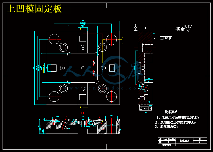
上凹模固定板.exb
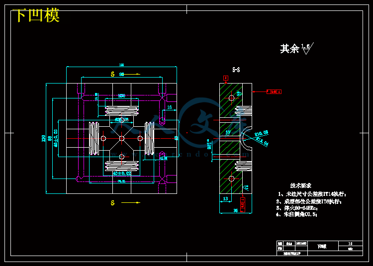
下凹模.exb
下凹模固定板.exb
动模座板.exb
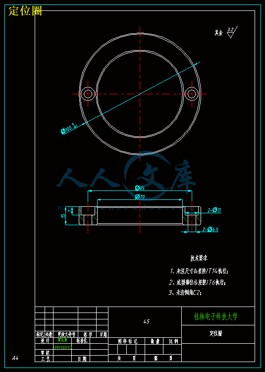
定位圈.exb
定模座板.exb
导套.exb
导柱.exb
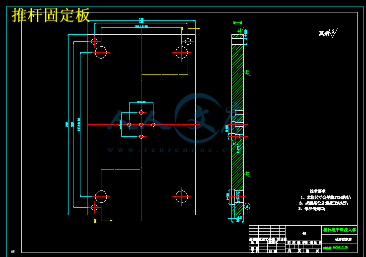
推杆固定板.exb
推杆支撑板.exb
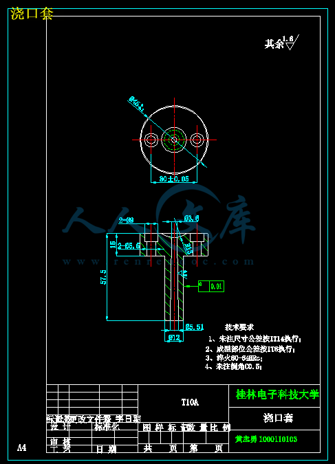
浇口套.exb
滑块.exb
滑块镶件.exb
装配图.exb
上凹模.dwg
上凹模固定板.dwg
下凹模.dwg
下凹模固定板.dwg
动模座板.dwg
定位圈.dwg
定模座板.dwg
导套.dwg
导柱.dwg
推杆固定板.dwg
推杆支撑板.dwg
浇口套.dwg
滑块.dwg
滑块镶件.dwg
装配图.dwg
压缩包内文档预览:(预览前20页/共41页)
预览图 预览图 预览图 预览图 预览图 预览图 预览图 预览图 预览图 预览图 预览图 预览图 预览图 预览图 预览图 预览图 预览图 预览图 预览图 预览图
编号:10115673    类型:共享资源    大小:4.14MB    格式:RAR    上传时间:2018-05-22 上传人:俊****计 IP属地:江苏
40
积分
关 键 词:
螺纹 罗纹 液压 四通 管接头 注塑 模具设计 15 cad 图纸 以及 说明书 仿单
资源描述:

摘  要


模具设计是工业生产中的重要工艺,是我国经济发展体系里的重要因素,好的模具能节省材料节省人力,节省时间,因此受到广泛的关注。注塑模是模具设计里的一种重要成型工艺,它主要用于热变形塑料的成形,也可以成形热固性塑料。它的生产效率极高,并且非常容易实现自动化,最重要的是生产出来的塑件质量都很好。注塑模形式多样,内容多样,结构复杂,对于它的发展也不会就此止步。

本次毕业设计的主要任务是对外螺纹液压管接头四通管模具的设计,也就是设计一副注塑模具来生产外螺纹液压管接头四通管的塑件产品,以实现自动化提高产量。主要内容包括绪论、塑件的结构及成型工艺分析、材料的选择及成型工艺、注射机的选择及校核、模具的工作及结构原理、浇注系统的设计、成型零部件的设计、侧向分型机构的设计、合模导向机构的设计、温度调节系统的设计、排气系统的设计、顶出机构的设计、支撑零部件的设计等。在设计过程种运用到了Proe3.0软件对塑件进行三维造型,通过使用AutoCAD来设计整套模具,并运用CAXA/CAD对其装配图与零件图等进行表述,设计过程中也借鉴到很多学者的著作,设计相对充实。

本文是探究四通管的注塑模具设计,详细描述了整套模具的设计过程。通过对整个模具设计的过程,进一步加深对注塑成型工艺的了解,同时也巩固了对成型工艺的类型、结构、工作原理等的理论知识,以及在实践中总结并掌握模具设计的关键要点和设计方法。


关键词: 外螺纹四通管;注塑模具;注射机;侧型芯滑块;


Abstract


This graduation design is the main task of the inclined tee mould design, namely a pair of injection mold is designed to produce the plastic parts of inclined tee products, in order to realize the automation to increase production. The main contents include design options and checking , mold and structural work principle , the introduction of gating system , structure and plastic parts molding process analysis , choice of materials and molding process , injection machine , designed molded parts , lateral sub- design mechanism design guide clamping mechanism , temperature control system design, the design of the exhaust system , the ejection mechanism designed to support the design of parts .

    This article is to explore the plastic injection mold design four line , a detailed description of the entire mold design process.Through the entire mold design process , and further deepen their understanding of the injection molding process , but also to consolidate the process of forming the type, structure and operating principles of the theory of knowledge, as well as summary and master mold design practice and design a key point methods.


Key words: oblique tee; Injection mould; Injection machine; Core side slide block; 


目    录


引言 1

2  塑件成型工艺的可行性分析 3

2.1  塑件分析 3

2.2 塑件的原材料分析 3

2.2.1主要技术指标 4

2.2.2 ABS的注射工艺参数 4

2.3 塑件的成型工艺分析 4

2.3.1精度等级 4

2.3.2脱模斜度 5

2.3.3塑件壁厚 5

3  注射成型机的选择与成型腔数的确定 5

3.1 注射成型机的选择 5

3.1.1估算零件体积和投影面积 5

3.1.2注射量的计算 6

3.1.3锁模力 6

3.1.4选择注射机及注射机的主要参数 6

3.2 注塑机的校核 6

3.2.1最大注塑量校核 6

3.2.2注射压力的校核 7

3.2.3锁模力校核 7

3.3 成型腔数的确定 7

4  浇注系统的设计 8

4.1 浇注系统的作用 8

4.2 浇注系统的组成 8

4.3 主流道设计 8

4.3.1 主流道设计要点 8

4.3.2浇口套的尺寸设计要求 9

4.4 浇口设计 10

4.6 主流道剪切速率校核 11

4.6.1估算主流道凝料体积 11

4.6.2主流道剪切速率校核 11

5  成型零件结构设计 12

5.1 分型面的设计 12

5.1.1分型面的分类 12

5.1.2分型面的选择原则 12

5.1.3分型面的确定 12

5.2 型腔的分布 13

5.3 凹模的结构设计 13

5.4 模具型零成件的工作尺寸计算 14

5.4.1塑件的收缩率波动误差s 14

5.4.3模具成型零件的磨损c 15

5.4.4模具安装配合误差j 15

5.5 型腔和型芯径向尺寸的计算 16

5.5.1型腔径向尺寸的计算 16

5.5.2型芯径向尺寸的计算 16

5.5.3型腔深度和型芯高度尺寸的计算 16

6  排气系统的设计 17

6.1 排气不良的危害 17

6.2排气系统的设计方法 17

7  导向与脱模机构的设计 18

7.1导向机构的作用和设计原则 18

7.1.1导向机构的作用 18

7.1.2导向机构的设计原则 18

7.2导柱、导套的设计 18

7.2.1导柱的设计 18

7.2.2导套的设计 19

7.2.3导向孔的总体布局 19

7.3 推出机构设计 19

7.4 脱模力的计算 20

7.5 推杆的设计 21

7.5.1推杆长度及强度计算 21

7.5.2推杆的形状及固定形式 22

7.2.3推杆位置的选择 23

8侧向分型与抽芯机构的设计 24

8.1 抽芯机构设计原则 24

8.2 抽芯机构的确定 24

8.3 抽芯距S 24

8.4 滑块的设计 24

8.5 导滑槽的设计 25

8.6 锁紧块 25

8.7 锁紧块的结构形式 26

9冷却系统设计 26

9.1 冷却系统的设计原则 26

9.2 温度调节对塑件质量的影响 27

9.3 对温度调节系统的要求 27

9.4 冷却装置的设计要点 27

9.5 冷却系统设计计算 27

9.5.1冷却水的体积流量 27

9.5.2冷却水管直径 28

9.5.3冷却水道的结构 28

10  其它结构零部件的设计 29

10.1 模具安装尺寸校核 29

10.2 开模行程的效核 29

11小结 30

参考文献 31

致  谢 32


引言

注塑成型是一项越来越成熟的加工技术,它目前是在塑性成型的各个领域加工中最常见也最常用的加工方法,其中注塑模具已经被广泛的采用,在很多方面的应用都得到相当高的重视[12]。我国模具研究单位因此也投入了很大的科研精力,目的在于使注塑模具的发展得到最大的提高。它的生产零件的质量、模具的结构、温度调控系统、制造精度、生产周期以及生产效率的高低,直接影响到产品的质量、产量和成本。当今社会,我们追求的正是质量与成本,统称为性价比,模具的应用正是性价比的最高体现,有的时候我们用一个模具可以同时制造出很多个质量精良,结构复杂的高精度塑件,这在以前来说几乎是不可能实现的[2]。注塑成型现已被广泛的应用于机械、计算机、高科技材料、电子、航空、航天、军工、学习用品、交通、汽车、建材、医疗器械、生物、能源和日用品等领域[1]。虽然在很多人看来一个小小的模具制造工艺能有多大的影响对于一个国家的发展,我觉得这种想法是错误的,因为从小方面来说这一门技术的成熟意味着对塑件成型的深入研究取得了长足进步,也就是说我们生产塑件就会更加便捷也会更加快速,这对于塑料工业来说是一个很大的贡献,因此不容小视;大方面来说正是这种对于先进技术的渴望推动我们整个民族在进步,我们知道我们在清政府以后闭关锁国导致在科技方面落后西方一大截,但我们中华民族从来没有服输过,一直都是在迎头赶上,只为了争这一口气,而注塑模的研究进步正是对我们的一种肯定,因此我们应当不遗余力的继续在这条路上走下去。我国近年来一直致力于模具的研究,现在也已经逐步跟上了欧美先进的步伐。在一些发达国家,模具产业早已形成产业链,成为这些国家的基础经济工业之一。很多国家在发展高科技产业的同时也兼顾发展轻工业,在美国,模具工业被成为“美国工业的基石”,在日本被称为“促进社会富裕的动力、源泉”[3]。因此在轻工业行业有这么一句话:工业要发展,模具要先行。没有高水平的模具制造工艺就没有质量非常优良的科技产品。现在,模具工业水平是衡量一个国家制造工业制造水平高低的重要标志。可以这么大胆的预测,模具工业在国民经济中的地位将与日俱增,并且扮演越来越重要的角色。因此我们必须毫无疑虑的发展模具工业,对于我们国家的生产力的进步有很大的推动作用。


内容简介:
编号: 毕业设计(论文)外文翻译(译文)学 院: 专 业: 机械设计制造及其自动化 学生姓名: 学 号: 指导教师单位: 姓 名: 职 称: 2014 年 3 月 9 日0微透镜阵列注塑成型技术摘要微透镜阵列注塑成型,可作为一种非常重要的大量生产技术。因此我们在近来的研究中非常关注, 为了进一步了解注塑成型在不同的加工条件下对可复制的微透镜阵列剖面的影响,如流量、填料压力和填料时间,对 3 种不同的高分子材料(PS,PMMA和 PC)进行了大量的试验。 镍金属模具嵌件微阵列就是利用改良的 LIGA 技术电镀主装配的显微结构制造的。在表面轮廓得到测量的前提下,研究工艺条件对可复制的微透镜阵列的影响。实验结果表明, 填料压力和流速对注射模塑的终产品的表面轮廓有重要的影响。 原子力显微镜测量表明, 微透镜阵列注塑成型的平均表面粗糙度值小于模具嵌件成型, 并在实际运用中,能与精细的光学元件相媲美。1 说明微型光学产品,如微透镜或微透镜阵列已广泛应用于光学数据存储、生物医学、显示装置等各个光学领域。微透镜和微透镜阵列不仅在实践应用上,而且在微型光学的基础研究上都是非常重要的。有几种微透镜或微透镜阵列的制作方法,如改良的LIGA 技术,光阻回流进程,紫外激光照射等。还有复制技术,如注塑模压成型和热压技术 ,这种方法对于减少大规模生产的微型光学产品的成本尤为重要。由于其优越的生产和再生产能力,只要注塑成型过程中能很好的复制微观结构,那么肯定是最适合于降低大量生产成本的方法。基于这点,检查注塑成型能力并确定成型加工条件是注塑成型微观结构过程中最重要的步骤。在本次研究中,我们考察了工艺条件对可复制的微透镜阵列的注射成型的影响。微透镜阵列是用之前介绍过的改良的 LIGA 技术来编制的。注塑成型实验采用的是一种镀镍金属模具,来探讨了几种不同工艺条件对成型的影响。通过对微透镜阵列的表面轮廓测量,用来分析工艺条件产生的影响。最后,利用原子力显微镜(AFM)测量微透镜的表面粗糙度值的大小。12 模具嵌件的制造利用改良的 LIGA 技术,在一个有机玻璃板上制造出具有几种不同直径微透镜阵列。此种技术是先用 X 光照射有机玻璃板,然后再进行热处理两部分构成的。 X-射线照射引起有机玻璃分子质量的减少,同时降低了玻璃化转变温度,并因此导致净含量的增加,在热循环的作用下,微透镜发生微膨胀。利用中提出的方法,结合改良的LIGA 技术可以预测微透镜形状的变化过程。 在试验中使用的微透镜阵列,有 500m (22 阵列 ),300m (22)和 200m (55)的直径阵列,高分别是 20.81m,17.21m 和 8.06m。采用改良的 LIGA 技术制造微透镜阵列作为一个主要的技术,用来制作镀镍的金属模具的注塑成型。另一些特殊材料,因为它们的强度不够或热性能差而不能直接进行微细加工,当作模具或金属模具使用,如硅、光阻剂或高分子材料。尽量使用具有良好机械性能和热性能的金属材料,因为它们能在可复型加工过程中经受高压力和不断变化的温度。因此,为了利用这种复制技术进行大批量生产,我们选择使用金属模具材料而不是有机玻璃硅晶体。一些特殊技术,如低压注塑成型8 技术,应该作为良好的复制加工方法被采纳。电镀模具的最终大小为 30 mm30 mm3mm。镀镍金属模具所具有的微透镜阵列如图 1 所示。图 1 镀镍模具嵌件的制造 (a)直接观察;( b)直径为 200m 的微透镜阵列电子显微镜图像;(c)直径为 300m 的微透镜阵列电子显微镜图像23 注塑成型实验传统注塑机(Allrounders 220 M,Arburg)多用做实验机。注塑模具设计的模架就是利用一块框形支撑板固定镀镍模具(如图 2 所示)。图 2 注塑模具实验中使用的模架和嵌件用修改的微透镜阵列确定模具零件孔形加强板(在这次实验中,是一块矩形板)的外部形状。模架本身已含有传输系统,如注射口,流道及浇口,通过支撑板、模具流道和滑动的模具表面将熔融聚合物引入模腔。用这种方法设计的模架,能够使模具零件更换起来简单容易。不过,有时候也使用具有特定孔径形状的支撑板。 实验主要用三种普通高分子材料,PS(615APR,陶氏化学),有机玻璃(IF870 , LG MMA)和 PC(Lexan 141R)进行注塑成型。这些高分子材料通常在光学元件上使用,它们有不同的折射率(PS,PMMA 和 PC 的折射率分别为 1.600,1.490 和 1.586),能生产出具有不同的光学特性的产品,例如:具有相同的几何尺寸却有不同的焦距的光学元件。通过改变每个高分子材料的流速,充填压力和充填时间获得 7 种加工条件进行注塑成型试验。此外,为了检查是否能可再生产,同一实验往往需要重复三次。可能有人会指出,实验中没有考虑模具温度的影响,这是因为温度效应相对来说不是主要因素,而且微透镜阵列曲率半径比其他微观结构的高宽纵横比大。正是因为较大的微观结构高宽纵横比,使我们目前研究的温度效应更加可靠,并计划在将来实验时进行单独报告。 因此,在这项研究中,我们保持模具温度不变,而流速、充填压力和充填的时间都变化的情况下,能更清楚的观察其产生效果。表 1 详细的列出了三种高分子材料 PC, PMMA 和 PS 在其他加工条件都保持不变,将模具温度分别设定为 80,70和 60的情况下的实验结果。表 1 注塑模具实验中详细的工艺条件序号 流 速 (cc/s) 充填时间 (/s) 充填压(MPa)1 12.0 5.0 10.032 12.0 5.0 15.03 12.0 5.0 20.04 12.0 2.0 10.05 12.0 10.0 10.06 18.0 5.0 10.0PS7 24.0 5.0 10.01 6.0 10.0 10.02 6.0 10.0 15.03 6.0 10.0 20.04 6.0 5.0 10.0PMMA566.09.015.010.010.010.0续表 1序号 流 速 (cc/s)充填时间 (/s)充填压力(MPa)7 12.0 10.0 10.01 6.0 5.0 5.02 6.0 5.0 10.0355.010.015.05.066.06.09.0 5.0 5.0PC7 12.0 5.0 5.0可能有人会指出,我们的实验没有考虑型腔出现真空状态时的情况,其实大可不必担心,因为在本研究中的注射阶段,大曲率半径的微透镜阵列不会把空气引入到型腔中。4 讨论和结果在详细讨论实验结果之前,认真思考一下,可能有助于总结为什么流速、充填压力和充填时间( 在这项研究中被选为不同的加工条件)影响复制的质量。就流速而言,可能存在一个最佳流速,而在完成充填之前,流速太小会使得熔融聚合物过冷却,从而可能导致所谓的短暂的不连续现象,而过高的流速增大了压力面积,这是不可取的。充填阶段是一般要求,是要在冷却时能够弥补热熔融聚合物的体积收缩 。 因此,4在这个阶段应有足够的熔融聚合物流入型腔并控制产品的尺寸精度。 越高的充填压力,越长的充填时间,将使更多的材料持续不断的流向型腔。然而, 过高的充填压力,有时可能造成不均匀的密度分布,从而产生劣质的光学质量。过长的充填时间,不利于在各自浇口处的冷凝,并且会阻止熔融聚合物流入型腔。因此,我们需要研究不同的充填压力和充填时间所产生的影响。4.1 表面轮廓图 3 所示的是用电子显微镜(SEM) 扫描的不同注塑微透镜的直径的 PMMA 图像(a)以及不同 材料的图像 (b)。代表性的模具表面轮廓以及所有注塑微阵列都是通过三维轮廓测量系统(NH-3N , Mitaka)测定的。图 3 注塑模具的微透镜阵列和微透镜的电子显微镜图像(a)PMMA 微透镜阵列 (b)不同材料直径为 300m 微透镜阵列的注塑模具作为一个可复制阵列的测量工具,我们已经确定了在模具与相应的模具嵌件分开的微阵列之间轮廓的相对高度偏差,所有的微透镜阵列相对偏差值列在表 2 中,具体见表所示:表 2 表面轮廓相对偏差相对偏差(%)直径 (m) 1 2 3 4 5 6 7PS200300500-7.625.862.38-7.592.03-0.382.082.860.51-5.565.611.47-8.6660.161.47-11.444.291.47-9.475.731.955PMMA 2003005007.205.77-0.661.315.60-1.62-3.886.453.98-5.805.952.80-0.975.95-0.72-8.536.68-0.904.86-2.62-0.72PC20030050023.026.20-0.9316.054.965.0916.872.66-1.8619.664.531.8833.974.786.9618.671.792.43-2.944.15-1.55值得一提的是,高分子材料的塑性会影响其重复使用性能。 因此在研究中,三种高分子材料总的相对误差是各不相同的。PC 是三种聚合物中最难注塑成型的材料。在直径最小的例子中产生最大的相对偏差,那都是意料之中的事。 在这种特殊情况下,充填时间并不对偏差产生显著影响,最好的解决方法是采用相对低的流速和充填压力。PS 和 PMMA 最小的直径的相对偏差要比 PC 小的多。 从表 2 可以看出,直径越大,相对偏差越小。当然,在注射和保压阶段,直径大的微透镜阵列容易比直径小的更容易填补,不管是在什么加工条件下和使用什么材料,大直径的微透镜阵列一般都能得到较好的复型。研究发现直径 500m 的 PS 最好复型,一般而言,与 PMMA 和 PC 相比较,PS 具有良好的成型性能。根据表 2 的数据,在考察最小的直径的 PS 和 PMMA 的相对偏差时,可能会有人提出一些消极的观点,认为偏差过大,但是在这些数据中可以得到,高度上的绝对偏差在0.1m 左右,这是在测量系统误差范围以内。 所以,在解读复型实验数据时可以忽略这些消极的观点。 直径为 300m 的 PC 和 PMMA 微透镜表面轮廓分别如图 4 和图 5 所示。正如之前所述,在图 4 所示的 PC 中,越高的充填压力或越高流速复制微透镜时效果越好,而充填时间在这些复型例子中只起一点作用。如图所示,对于 PMMA 来说,充填压力和充填时间的作用微不足道;然而,流速对于 PC 也有类似的效果。 它可以提醒我们注意如果一个浇口冻结了,并阻止材料流入型腔时,充填时间并不影响复型。 因此,经过一段时间后,充填时间的影响,主要取决于加工条件。6图 4 直径为 300m 的 PC 微透镜表面轮廓 a 充填压力的影响 b 流速的影响 c 充填时间的影响 图 5 直径为 300m 的 PMMA 微透镜表面轮廓a 充填压力的影响 b 流速的影响 c 充填时间的影响4.2 表面粗糙度直径 300m 的微透镜和模具嵌件的平均表面粗糙度 Ra 的值,是用原子力显微镜(Bioscope AFM,数字仪表) 测量的。测量了每个微透镜顶点周围面积为 5m5m 区7域, 图 6 所示的是原子力显微镜图象和所测量的微透镜 Ra 的值。PMMA 微透镜复型具有最低的 Ra 值,为 1.606nm。通过 AFM 的测量表明,注塑成型微透镜阵列的 Ra 值比相对应的模具嵌件要小。 因此,现在还不清楚如何改善可复制微透镜阵列的表面粗糙度,也许可以从冷却过程的回流而造成的表面张力入手,它可能会进一步得出,在实际运用中,微透镜阵列注塑成型的平均表面粗糙度值能与精细的光学元件相媲美。a 镀镍模具嵌件 ; b PS; c PMMA; d PC图 6 直径为 300m 的模具嵌件和注塑模具微透镜的原子力显微镜(AFM)图像和平均表面粗糙度 Ra 值 4.3 焦距焦距可以通过下面这个著名的等式计算得出: 12()nfR式中 f,nl , R1 和 R2 分别指焦距,透镜材料的折射率,两个主曲率半径。比如,根据等式可以计算得出,直径为 200m 的模具微透镜的焦距大约为 1.065mm(其中R1=0.624mm 和 R2=),直径 300 的微透镜大约为 1.130mm (其中 R1=0.662mm 和R2=) ,直径 500m 的微透镜大约为 2.580mm(其中 R1=1.512mm 和 R2=)。 (1)这些计算结果是基于假设与模具嵌件具有相同形状的 PC(nl=1.586)可复型的微透镜而得到的,所以由此推导出的几何尺寸可能与实验所测量的焦距相反。85 总结 通过使用改良的 LIGA 技术电镀镍金属模具嵌件,改变各种加工条件进行大量的实验,研究工艺条件对可复型的微透镜的注塑成型过程的影响。结果显示越高的充填压力或越高流速,能得到越好的可复型效果。 相比之下,充填时间对微透镜阵列复型的影响却很小。也许是因为冷却阶段回流的表面张力造成的,注射成型微透镜阵列比模具嵌件有更小的平均表面粗糙度值,PMMA 复型的微透镜阵列具有最好的表面质量(即最低粗糙度值 Ra=1.606 nm)。在实际应用中,注塑成型微透镜阵列的表面粗糙度能与精密的光学元件相媲美。就凭这一点,注塑成型将成为大规模生产微透镜阵列的一个有用方法。编号: 毕业设计(论文)外文翻译(原文)学 院: 专 业: 机械设计制造及其自动化 学生姓名: 学 号: 指导教师单位: 姓 名: 职 称: 2014 年 3 月 9 日The technology of Microlens array injection moldingAbstract Injection molding could be used as a mass production technology for microlens arrays. It is of importance, and thus of our concern in the present study, to understand the injection molding processing condition effects on the replicability of microlens array profile. Extensive experiments were performed by varyingprocessing conditions such as flow rate, packing pressure and packing time for three different polymeric materials (PS, PMMA and PC). The nickel mold insert of microlens arrays was made by electroplating a microstructure master fabricated by a modified LIGA process. Effects of processing conditions on the replicability were investigated with the help of the surface profile measurements. Experimental results showed that a packing pressure and a flow rate significantly affects a final surface profile of the injection molded product. Atomic force microscope measurement indicated that the averaged surface roughness value of injection molded microlens arrays is smaller than that of mold insert and is comparable with that of fine optical components in practical use.1 Introduction Microoptical products such as microlenses or microlens arrays have been used widely in various fields of microoptics, optical data storages, bio-medical applications, display devices and so on. Microlenses and microlens arrays are essential elements not only for the practical applications but also for the fundamental studies in the microoptics. There have been several fabrication methods for microlenses or microlens arryas such as a modified LIGA process 1, photoresist reflow process 2, UV laser illumination 3, etc. And the replication techniques, such as injection molding, compression molding 4 and hot embossing 5, are getting more important for a mass production of microoptical products due to the cost-effectiveness. As long as the injection molding can replicate subtle microstructures well, it is surely the most cost-effective method in the mass production stage due to its excellent reproducibility and productivity.In this regard, it is of utmost importance to check the injection moldability and to determine the molding processing condition window for proper injection molding of microstructures. In this study, we investigated the effects of processing conditions on the replication of microlens arrays by the injection molding. The microlens arrays were fabricated by a modified LIGA process, which was previously reported in 6, 7. Injection molding experiments were performed with an electroplated nickel mold insert so as to investigate the effects of some processing conditions. The surface profiles of molded microlens arrays were measured, and were used to analyze effects of processing conditions. Finally, a surface roughness of microlens arrays was measured by an atomic force microscope (AFM).2 Mold insert fabricationMicrolens arrays having several different diameters were fabricated on a PMMA sheet by a modified LIGA process 6. This modified LIGA process is composed of an X-ray irradiation on the PMMA sheet and a subsequent thermal treatment. The X-ray irradiation causes the decrease of molecular weight of PMMA, which in turn decreases the glass transition temperature and consequently causes a net volume increase during the thermal cycle resulting in a swollen microlens 7. The shapes of microlenses fabricated by the modified LIGA process can be predicted by a method suggested in 7.The microlens arrays used in the experiments were composed of 500m -(a 2 2 array), 300m -(2 2) and 200m (5 5) diameter arrays, and their heights were 20.81, 17.21 and 8.06 m, respectively. Using the microlens arrays fabricated by the modified LIGA process as a master, a metallic mold insert was fabricated by a nickel electroplating for the injection molding. Typical materials used in a microfabrication process, such as silicon, photoresists or polymeric materials, cannot be directly used as the mold or the mold insert due to their weak strength or thermal properties. It is desirable to use metallic materials which have appropriate mechanical and thermal properties to endure both a high pressure and a large temperature variation during the replication process. Therefore, a metallic mold insert is being used rather than the PMMA master on silicon wafer for mass production with such replication techniques. Otherwise special techniques should be adopted as a replication method, e.g. a low pressure injection molding 8.The size of final electroplated mold insert was 30 30 3 mm. The electroplated nickel mold insert having microlens arrays is shown in Fig. 1.Fig.1.Moldinsert fabricated by a nickel electroplating (a) Real view of the mold insert (b) SEM image of 200 m diameter microlens array (c) SEM image of 300 mdiameter microlens array3 Injection molding experimentsA conventional injection molding machine (Allrounders 220 M, Arburg) was used in the experiments. A mold base for the injection molding was designed to fix the electroplated nickel mold insert firmly with the help of a frametype bolster plate (Fig. 2). Shape of aperture of the bolster plate (in this study, a rectangular one) defines the outer geometry of the molded part on which the profiles of microlens arrays are to be transcribed. The mold base itself has delivery systems such as sprue, runner and gate which lead the molten polymer to the cavity formed by the bolster plate, the mold insert and amoving mold surface. The mold base was designed such that mold insert replacement is simple and easy. Of course, one may introduce an appropriate bolster plate with a specific aperture shape. Fig. 2. Mold base and mold insert used in the injection molding experimentThe injection molding experiments were carried out with three general polymeric materials PS (615APR, Dow Chemical), PMMA (IF870, LG MMA) and PC (Lexan 141R, GE Plastics). These materials are quite commonly used for optical applications. They have different refractive indices (1.600, 1.490 and 1.586 for PS, PMMA and PC, respectively), giving rise to different optical properties in final products, e.g. different foci with the same geometry. The injectionmolding experiments were performed for seven processing conditions by changing flow rate, packing pressure and packing time for each polymeric material. Furthermore, same experiments were repeated three times for checking the reproducibility. It may be mentioned that the mold temperature effect was not considered in this study since the temperature effect is relatively less important for these microlens arrays due to their large radius of curvature than other microstructures of high aspect ratio. For high aspect ratio microstructures, we are currently investigating the temperature effect more closely and plan to report separately in the future. Therefore, flow rate, packing pressure and packing time were varied to investigate their effects more thoroughly with the mold temperature unchanged in this study. Table 1 shows the detailed processing conditions for three polymeric materials. Other processing conditions were kept unchanged during the experiment. The mold temperatures were set to 80, 70 and 60 _C for PC, PMMA and PS, respectively.It might be mentioned that we carried out the experiments without a vacuum condition in the mold cavity considering that the large radius of curvature of the microlens arrays in the present study will not entrap air in the microlens cavity during the filling stage.Table 1. Detailed processing conditions used in the injection molding experimentsCase Flow rate (cc/sec)Packing time (sec)Packing pressure(MPa)1 12.0 5.0 10.02 12.0 5.0 15.03 12.0 5.0 20.04 12.0 2.0 10.05 12.0 10.0 10.06 18.0 5.0 10.0PS7 24.0 5.0 10.01 6.0 10.0 10.02 6.0 10.0 15.03 6.0 10.0 20.0PMMA 4 6.0 5.0 10.05676.09.012.015.010.010.010.010.010.01 6.0 5.0 5.02 6.0 5.0 10.0355.010.015.05.066.06.09.0 5.0 5.0PC7 12.0 5.0 5.04 Results and discussionBefore detailed discussion of the experimental results, it might be helpful to summarize why flow rate, packingpressure and packing time (which were chosen as processing conditions to be varied in this study) affect thereplication quality. As far as the flow rate is concerned, there may exist an optimal flow rate in the sense that too small flow rate makes too much cooling before a complete filling and thus possibly results in so-called short shot phenomena whereas too high flow rate increases pressure fields which is undesirable.The packing stage is generally required to compensate for the volume shrinkage of hot molten polymer whencooled down, so that enough material should flow into a mold cavity during this stage to control the dimensionalaccuracy. The higher the packing pressure, the longer the packing time, more material tends to flow in. However, too much packing pressure sometimes may cause uneven distribution of density, thereby resulting in poor opticalquality. And too long packing time does not help at all since gate will be frozen and prevent material from flowing into the cavity. In this regard, one needs to investigate the effects of packing pressure and packing time.4.1 Surface profilesFigure 3 shows typical scanning electron microscope (SEM) images of the injection molded microlens arrays for different diameters for PMMA (a) and different materials (b). Cross-sectional surface profiles of the mold insert and all the injection molded microlens arrays were measured by a 3D profile measuring system (NH-3N, Mitaka).(a)Injection molded microlensarrays (PMMA) (b) Injectionmolded microlenses of 300 mdiameter for different materialsFig. 3. SEM images of theinjection molded microlensarrays and microlensesAs a measure of replicability, we have defined a relative deviation of profile as the height difference between the molded one and the corresponding mold insert for each microlens divided by the mold insert one. The computed relative deviations for all the microlenses are listed in Table 2.Relative deviation (%)Diameter( m)1 2 3 4 5 6 7PS200300500-7.625.862.38-7.592.03-0.382.082.860.51-5.565.611.47-8.6660161.47-11.444.291.47-9.475.731.95PMMA2003005007.205.77-0.661.315.60-1.62-3.886.453.98-5.805.952.80-0.975.95-0.72-8.536.68-0.904.86-2.62-0.72PC20030050023.026.20-0.9316.054.965.0916.872.66-1.8619.664.531.8833.974.786.9618.671.792.43-2.944.15-1.55It may be mentioned that the moldability of polymeric materials affects the replicability. Therefore, the overall relative deviation differs for three polymeric materials used in this study. It may be noted that PC is the most difficult material for injection molding amongst the three polymers. The largest relative deviation can be found in PC for the smallest diameter case, as expected. In that specific case, the largest value is corresponding to the low flow rate and low packing pressure. Packing time in this case does not significantly affect the deviation. The relative deviation for PS and PMMA with the smallest diameter is far better than PC case.Table 2 indicates that the larger the diameter, the smaller the relative deviation. The larger diameter microlens is, of course, easier to be filled than smaller diameter during the filling stage and packing stage. Microlenses of larger diameters were generally replicated well regardless of processing conditions and regardless of materials. The best replicability is found for the case of PS with 500 m diameter. Generally, PS has a good moldability in comparison with PMMA and PC.It may be mentioned that some negative values of relative deviation were observed mostly in the smallest diameter case for PS and PMMA according to Table 2. In these cases, however, the absolute deviation is an order of 0.1 m in height, which is within the measurement error of the system. Therefore, the negative values could be ignored in interpreting the experimental data of replicability. Surface profiles of microlens of 300 m diameter are shown in Figs. 4 and 5 for PC and PMMA, respectively. As shown in Fig. 4, the higher packing pressure or the higher flow rate results in the better replication of microlens for the case of PC, as mentioned above. Packing time has little effect on the replication for these cases. For the case of PMMA, the packing pressure and packing time have insignificant effect as shown in Fig. 5; however, flow rate has the similar effect to PC. It might be reminded that packing time does not affect the replicability if a gate is frozen since frozen gate prevents material from flowinginto the cavity. Therefore, the effect of packing time disappears after a certain time depending on the processing conditions.Fig.4ac(leftside).Surfce profiles of microlens (PC with diameter (/) of 300 m). a effect of packing pressure, b effect of flow rate, c effectof packing timeFig.5ac.(rightside)Surface profiles of microlens (PMMA with diameter(/) of 300m). a effect of packing pressure, b e
温馨提示:
1: 本站所有资源如无特殊说明,都需要本地电脑安装OFFICE2007和PDF阅读器。图纸软件为CAD,CAXA,PROE,UG,SolidWorks等.压缩文件请下载最新的WinRAR软件解压。
2: 本站的文档不包含任何第三方提供的附件图纸等,如果需要附件,请联系上传者。文件的所有权益归上传用户所有。
3.本站RAR压缩包中若带图纸,网页内容里面会有图纸预览,若没有图纸预览就没有图纸。
4. 未经权益所有人同意不得将文件中的内容挪作商业或盈利用途。
5. 人人文库网仅提供信息存储空间,仅对用户上传内容的表现方式做保护处理,对用户上传分享的文档内容本身不做任何修改或编辑,并不能对任何下载内容负责。
6. 下载文件中如有侵权或不适当内容,请与我们联系,我们立即纠正。
7. 本站不保证下载资源的准确性、安全性和完整性, 同时也不承担用户因使用这些下载资源对自己和他人造成任何形式的伤害或损失。
提示  人人文库网所有资源均是用户自行上传分享,仅供网友学习交流,未经上传用户书面授权,请勿作他用。
关于本文
本文标题:外螺纹液压管四通管接头注塑模具设计【15张CAD图纸和说明书】
链接地址:https://www.renrendoc.com/p-10115673.html

官方联系方式

2:不支持迅雷下载,请使用浏览器下载   
3:不支持QQ浏览器下载,请用其他浏览器   
4:下载后的文档和图纸-无水印   
5:文档经过压缩,下载后原文更清晰   
关于我们 - 网站声明 - 网站地图 - 资源地图 - 友情链接 - 网站客服 - 联系我们

网站客服QQ:2881952447     

copyright@ 2020-2024  renrendoc.com 人人文库版权所有   联系电话:400-852-1180

备案号:蜀ICP备2022000484号-2       经营许可证: 川B2-20220663       公网安备川公网安备: 51019002004831号

本站为文档C2C交易模式,即用户上传的文档直接被用户下载,本站只是中间服务平台,本站所有文档下载所得的收益归上传人(含作者)所有。人人文库网仅提供信息存储空间,仅对用户上传内容的表现方式做保护处理,对上载内容本身不做任何修改或编辑。若文档所含内容侵犯了您的版权或隐私,请立即通知人人文库网,我们立即给予删除!