CK20数控车床主传动系统设计(全套含CAD图纸)
收藏
资源目录

压缩包内文档预览:
编号:10132329
类型:共享资源
大小:5.32MB
格式:ZIP
上传时间:2018-05-31
上传人:机****料
认证信息
个人认证
高**(实名认证)
河南
IP属地:河南
50
积分
- 关 键 词:
-
ck20
数控车床
传动系统
设计
全套
cad
图纸
- 资源描述:
-

- 内容简介:
-
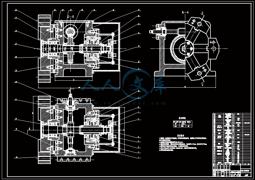
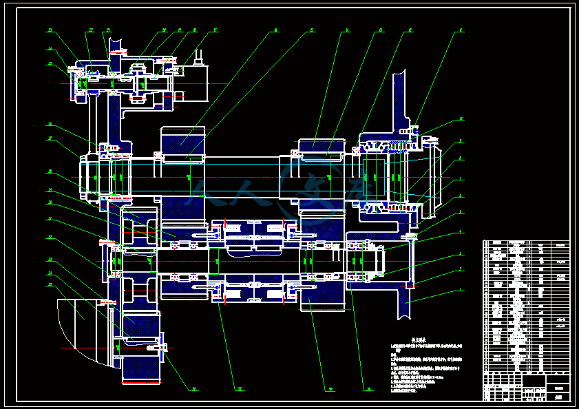
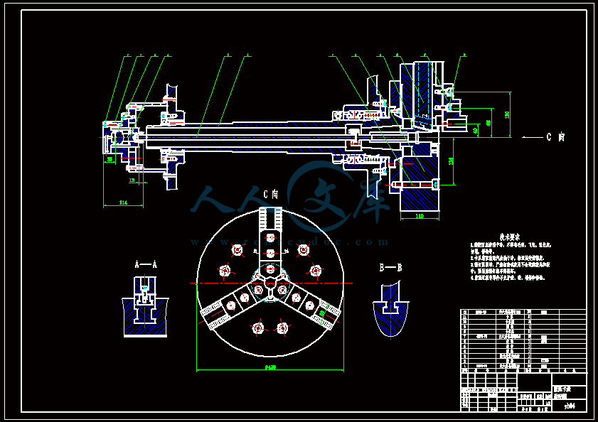
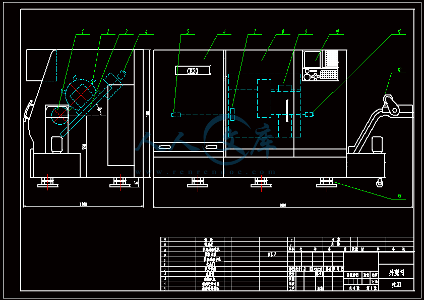
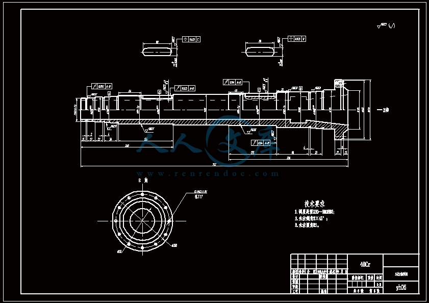
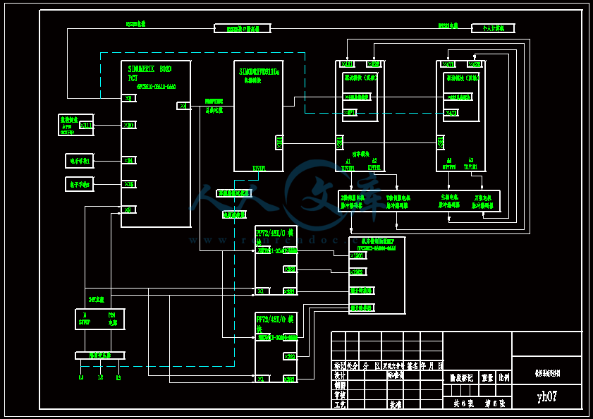
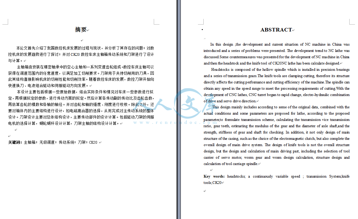
下载后包含有 CAD 图纸和说明书,咨询 Q 197216396 或 11970985摘要本论文首先介绍了我国数控机床发展的过程与现状,并分析了其存在的问题;对数控机床的发展趋势进行了探讨;并对 CK20 数控车床主轴箱传动系统和刀架进行了设计与计算。主轴箱由安装在精密轴承中的空心主轴和一系列变速齿轮组成。数控车床主轴可以获得在调速范围内的任意速度,以满足加工切削要求。刀架用于夹持切削用的刀具,因此其结构直接影响机床的切削性能和切削效率。随着数控车床的发展,数控刀架开始向快速换刀、电液组合驱动和伺服驱动方向发展。本设计主要包括根据一些原始数据,结合实际条件和情况对车床一些参数进行拟定,再根据拟定的参数,进行传动方案的拟定。然后计算各传动副的传动比及齿轮齿数,再估算齿轮的模数和各轴的轴径。并对齿轮和轴的强度、刚度进行校核。除此之外,还要对箱体内的主要结构进行设计,如电磁离合器的选择,从而完成对主传动系统的整体设计。刀架设计主要对总体结构设计,主要传动部件的设计计算。包括驱动刀架的伺服电机的选择计算,蜗轮蜗杆设计计算,刀架主轴的结构设计计算。关键词:主轴箱;无级调速;传动系统;刀架;CK20 下载后包含有 CAD 图纸和说明书,咨询 Q 197216396 或 11970985ABSTRACTIn this design ,the development and current situation of NC machine in China was introduced and a series of problems were presented. The development trend to NC lathe was discussed.Some countermeasures was presented for the development of NC machine in China and then the headstock and the knife tool of CK20NC lathe has been calculate designed.Headstocks is composed of the hollow spindle which is installed in precision bearings and a series of transmission gears.The knife tools are clamping cutting, therefore its structure directly affects the cutting performance and cutting efficiency of the machine.The spindle can obtain any speed in the speed range to meet the processing requirements of cutting.With the development of CNC lathes, CNC turret began to rapid change, electro-hydraulic combination of drive and servo drive direction.This design mainly includes according to some of the original data, combined with the actual conditions and some parameters are proposed for lathe, according to the proposed parameter,to formulate transmission scheme, calculating the transmission vice transmission ratio, gear teeth, estimating the modulus of the gear and the diameter of axle shaft,and the strength, stiffness of gear and shaft for checking. In addition, it not only design of main structure of the casing, such as the choice of the electromagnetic clutch, but also complete the overall design of main drive system. The design of knife tools is not the overall structure design, but the design and calculation of main driving part, including the selection of tool carrier of servo motor, worm gear and worm design calculation, structure design and calculation of tool carriage spindle.Key words: headstocks; a continuously variable speed ; transmission System;knife tools;CK20下载后包含有 CAD 图纸和说明书,咨询 Q 197216396 或 11970985-i-目 录第一章 绪论 11.1 课题背景及目的 11.2 国内外研究现状及发展趋势 11.2.1 我国数控车床的研究现状及发展趋势 11.2.2 数控系统的发展趋势 31.3 课题研究内容及方法 4 1.3.1 课题研究的主要参数 41.3.2 课题研究内容 41.3.3 研究方法 41.4 设计任务与论文构成 51.4.1 设计主要任务 51.4.2 设计的重点与难点 51.4.3 本论文构成如下 5第 2 章 机床总体方案的设计 62.1 机床的总体布局 6第 3 章 主传动系统的设计 73.1 总体设计 73.1.1 拟定传动方案 73.1.2 选择电机 83.1.3 计算各轴计算转速、功率和转矩 113.1.4 转速图与传动图 123.2 轴系部件的结构设计 133.2.1 I 轴结构设计 133.2.2 II 轴结构设计 173.2.3 III(主)轴结构设计 283.2.4 编码器的选择与安装设计 303.2.5 主传动系统总装图 32第 4 章 液压卡盘的设计(夹具) 344.1 卡盘夹紧机构的设计 34 下载后包含有 CAD 图纸和说明书,咨询 Q 197216396 或 11970985-i-4.2 液压卡盘系统总装图 34 第 5 章 数控刀架的结构设计 35 5.1 数控车床刀架总体方案设计与选择 355.1.1 刀架的整体方案设计 355.1.2 车床刀架的转位机构方案设计 355.1.3 刀架定位机构方案设计 365.2 刀架的设计计算 365.2.1 驱动刀架的伺服电机的选择计算 365.2.2 蜗轮蜗杆设计计算 395.2.3 刀架主轴的结构设计计算 425.3 刀架总装图 44第六章 数控系统的设计 467.1 线路连接 467.2 安装调试 47第七章 结论 48参考文献 49心得体会及致谢 50下载后包含有 CAD 图纸和说明书,咨询 Q 197216396 或 11970985-i-下载后包含有 CAD 图纸和说明书,咨询 Q 197216396 或 11970985-i-下载后包含有 CAD 图纸和说明书,咨询 Q 197216396 或 11970985-i-下载后包含有 CAD 图纸和说明书,咨询 Q 197216396 或 11970985-i-第一章 绪 论1.1 课题背景及目的近几年,我国的数控机床无论从产品品种,还是技术水平,或者品质和产量上都取得了很大的发展,并在一些关键技术方面取得了重大突破。特别是在通用微机数控领域,以 PC 平台为基础的国产数控系统,已经走在世界前列,让国人骄傲。据统计,在我国可供市场的数控机床就有 1500 种,几乎笼罩了整个金属切削机床行业的品种类别和主要的锻压机械。这表明了国内数控机床已经进入了快速发展的时期。 而相对于传统机床,数控机床则表现出有以下的优越性:1、数控加工工艺的“内容十分具体、工艺设计工作相当严密”。 2、能够实现加工的柔性自动化。3、粗精加工与加工精度的结合,装配就比较容易,不需要“修配”。 4、数控加工的工艺“复合性”,可完成多道工序的集中。 5、精密设备与一般设备的结合,可实现长时间的无人看管加工。 因此,采用数控机床,既可以降低工人的劳动强度,也可以节省劳动力(一个人可以看管多台机床),还能减少工装,缩短新产品试制周期和生产周期,对市场需求作出迅速反应。对此,数控技术已经成为制造业自动化的核心技术和基础技术。 由于以上优越性,数控机床所占的比例正在一步步地增大。从 2005 年的市场生产消费内容就可以明显看出,普通机床的市场份额在下降,数控机床的市场份额则大幅度增长,特别是中高档数控机床需求供不应求。在这样一种背景下,我的课题选择为设计一台数控车床CK20,用于对回转体零件的圆柱面、圆弧面、圆锥面、端面、切槽、及各种公、英制螺纹等进行批量、高效、高精度的自动加工。应用于飞机汽车航空航天、军工、电力等领域,实现加工自动化,提高产品质量,提高生产效率 1。1.2 国内外研究现状及发展趋势1.2.1 我国数控车床的研究现状及发展趋势1、研究现状我国数控车床从 20 世纪 70 年代初开始进入市场,通过各大机床厂家的不懈努力,通过采取与国外著名机床厂家的一系列措施,使得我国的机床制造水平程度有了很大提高,其产量在金属切削机床中占有较大的比例。目前,国产数控车床的种类、规格也比较齐全,质量基本趋于稳定可靠,已进入实用和全面发展阶段。下载后包含有 CAD 图纸和说明书,咨询 Q 197216396 或 11970985-i-(1)床身按照床身导轨面与水平面的相对位置来分,床身有图 1.1 所示的 5 种布局形式。一般来说,斜床身和平床身斜滑板在中、小规格的数控车床采用较多,平床身只有在大型数控车床或小型精密数控车床才被采用,立床身一般不被采用。在机床中一般采用平床身斜滑板结构,再配置上倾斜的导轨防护罩,这样既保持了能有效利用空间,大大减小了机床的平面占地位置,床身宽度也不会太大,又有利于克服重力有更好的稳定性来提高机床精度,有利于机床的清扫清洁工作,使得切屑不容易堆积。a)后斜床身-斜滑板 b)直立床身- 直立滑板 c)平床身-平滑板 d)前斜床身- 平滑板 e)平床身-斜滑板 图 1.1 床身布局型式(2)导轨 导轨的功用是承受载荷和导向。它承受安装在导轨上的运动部件及工件的重力和切削里,运动部件能够沿导轨运动。车床的导轨按照导轨面的摩擦性质可分为滑动导轨和滚动导轨两种。 下载后包含有 CAD 图纸和说明书,咨询 Q 197216396 或 11970985-i-滑动导轨具有结构简单、制造方便、接触刚度大等优点。滚动导轨的优点是摩擦系数小,动、静摩擦系数很接近,因此摩擦力小,轻动方便,运动灵敏,不易爬行。(3)主轴变速系统一般说来,经济型数控车床大多数是不能自动变速的,全功能数控车床的主传动系统大多采用无级变速。目前,无级变速系统一般采用直流或交流主轴电机,通过带传动带动主轴旋转,或通过带传动和主轴箱内的减速齿轮带动主轴旋转。由于主轴电机调速范围广,又可无级调速,使得主轴箱的结构大为简化。(4)刀架系统 小规格数控车床一般采用排式刀架,以加工棒料或盘类零件为主。数控车床最常用的一种典型换刀刀架是回转刀架,它通过刀架的旋转分度定位来实现机床的自动换刀动作,根据加工要求可设计成四方、六方刀架或圆盘式刀架。排刀式刀架和回转刀架都使得刀具的数目受到一定的限制,当需要数量较多的刀具时,应采用带刀库的自动换刀装置。(5)进给传动系统 进给伺服系统是数控车床的进给传动系统主要采用的系统,按其控制方式不同可分为开环系统和闭环系统。闭环系统控制精度高、快速性能好,但它对机床的要求比较高,且造价较昂贵;而开环系统定位精度低,但它结构简单、工作可靠、造价低廉。进给伺服系统中在数控系统常用的驱动装置是伺服电机。进给伺服电机有直流伺服电机和交流伺服电机之分。2、发展趋势 高速、高精密化 高可靠性 CAD 化、结构设计模块化 功能复合化 数控车床设计智能化、网络化、柔性化和集成化。 提高数控机床产品的自主开发、制造能力。 以功能部件为基础,以关键共性技术为支撑;加快技术引进与国际合作 1。1.2.2 数控系统的发展趋势1、继续向开放式、基于 PC 的第六代方向发展 2、向高速化和高精度化发展 3、向智能化方向发展 (1)应用自适应控制技术向高速化和高精度化发展 (2)引入专家系统指导加工 (3)引入故障诊断专家系统 开发低成本接触触发探测器的数控车床马塞洛德尔战争 a雷吉纳尔多特谢拉科埃略 ba:工程圣卡洛斯 - 欧盟经济社会委员会,USP 的冼星海大马路工人Sancarlense400,CEP13566-590,圣保罗卡洛斯,SP,巴西的学校b:工程圣卡洛斯 - 欧盟经济社会委员会,USP 的冼星海大马路工人Sancarlense400,CEP13566-590,圣保罗卡洛斯,SP,巴西的学校2006 年 4 月 18 日网上可查询摘要数控机床使用触发式测头已成为世界标准,主要是由于减少了机器设置时间,以促进工件精度在机测量的能力。然而,一些障碍仍然需要调换,如测量程序编程困难,这些设备的成本高和技术文献的数量较少有关此主题。这项工作提出的触发式测头对车间的应用,讨论时下用来产生触发信号的技术审查。基于简单的电接触的新接触触发探头模型被提出,与所需要的特性和成本低,要用于 CNC 车床。探针在实验室开发的试验示出 0.003 毫米(3 秒或 99.73置信区间)一个可重复性。这些特征似乎是非常媲美于工业车床应用中最需要的。关键词: 尺寸质量监测和控制;接触触发探头; 在机测量系统;CNC 车床简介如今,在制造系统发展最困难的挑战是实现地区生产的全维管理,创建统计数据分析和部分到零件的控制。这种融合可以通过使用通常被称为连接到数控机床触发式测头设备来达到。这些设备是用于基于项目的规格,闭环过程控制,部件的尺寸控制。制造,刀具补偿,快速设置,过程的统计数据采集和更多的测量和校准。它是在目前的制造系统的发展趋势非常重要的是要使用这些功能,使得可能部分对部分检验控制,如果必要的,这保证了尺寸误差立即检测,减少废料,避免了一整批片都刮掉并降低成本,由于零件返工。为了帮助维控上车削操作,这项工作开始引入触发式探头的特点,用于产生“触发信号”技术。在此之后,本文提出了一种简单和低成本的无线触发式测头的基础上,直接电接触的原则。原型是一起提交的重复性和准确性的研究。1.触发式测头第一个触发式测头的发明是为了解决一个具体的检查要求,但继续改造的设计和革命性的制造组件的过程后检验使用三坐标测量机(CMM)的。在 20 世纪 70 年代末,几乎所有主要的 CMM 制造商在世界上采用雷尼绍探头。后来,由于数控进展,包括测量功能和直线光栅尺在其轴,使用这种装置传到机床,在那里他们成为了自动化生产系统,使得企业,从汽车到航空航天,提供精密零件的重要组成部分,减少废料和最大限度地提高工作效率。大卫麦克默特里开发的触发式测头技术在 1972 年的问题出现在劳斯莱斯公司,在那里他是引擎设计的副总。当时,他正面临着测量一些复杂的管路,只有毫米直径 6,对协和使用奥林巴斯引擎的问题。该管道必须适合精确扎实座架之间,但难度来衡量他们,一旦他们被制造。发现该溶液是触发式探头(TTP),它使用了一个简单的原则,以确定探针和部件之间的接触,以进行测量。 1973 年,大卫麦克默特里注册了一家名为雷尼绍早期成为计量和光谱解决方案的领先供应商,制造商和研究人员在世界各地(雷尼绍1)。由于公司使用的专利机制,由打算加入这个市场上的其他公司需要开发其他技术。3.触发式测头主要特点独立使用的技术,其原理是基于电信号此刻探头的尖端接触要测量的部分的产生(或中断)。该信号,一般称为触发信号,被发送到把它转换到由数控或 CMM 的被读出的接口。在该机器接收到触发信号的那一刻,它会立即冻结,并保存为计算和报告生成轴值(见图例如 1)。图.1.连接到数控机床的测量系统。红外线,无线电频率或简单的电线电缆:从 TTP 到探头接口触发信号传输可以采用三种基本不同的通信技术来建立。红外通信用于标准车床和铣床传统的应用;这种技术提供了高可靠性,高传输速度率,低噪音干扰和低实施成本。这是接近万无一失的系统,除非探头和接收器都出视觉接触的,作为探针深工件内孔或其他凹陷内时。对于这些情况和应用中,射频系统建议,(工具及制造2)。电线电缆通讯用于它们被安装并固定在机床工作台刀具调整器的探针。4.探测循环和编程据现代机加工在线3,少数专业人士会提出异议探测超速零件设置,设置刀具补偿和执行过程中的检验,至少在理论上的优点。在实践中,然而,探测器系统经常被看作是难于使用和昂贵,购买。其结果是,他们已经成为在高生产环境主要由有经验的程序员的工具。为了使探测有效,更经济实惠的范围广泛的用户,一些主要领导的 CNC 的制造商,如发那科,海德汉,大隈,辛辛那提米拉克龙公司和西门子,都包括在其数控软件,专门开发的图形用户友好界面用于探测的 Heidenhain TNC 控制系列,例如,能够自动地或手动地通过三维测量,使检查的功能,如检查孔的尺寸精度,确定饲料进行精加工,检查工件的几何形状,并确定从公差偏差,确定工件前加工和扫描三维表面。另外,探测循环正在广泛开发和可以由单个线的信息来激活(Zhou 等人4)。今天的标准机床提供精度和可重复性接近以前的水平仅在三坐标测量机。此外,技术的进步使这些机器容易维护。测试和校准技术,现已启用的商店,以确保其机床的精度和健康。伸缩式球杆仪是由几乎所有的商店很容易负担得起的。一个藏书丰富的工具箱中也应包含电子水平还是不错的一套精密机床的水平。植物和大商店越来越多维护自己的激光干涉仪和电子水平,而租赁设备和诊断服务可购到各种来源的小商店(现代机加工在线5)。另外,根据现代机加工在线6,CNC 机器,在一般情况下,非常准确,非常重复。他们媲美同等规模的三坐标测量机的精度和可重复性。随着在 CNC 检查过程中的一些照顾,导致测量误差和错误切割之间相互依存的因素可以被最小化。5.技术用于生成所述触发信号根据沉和月亮7,有当探针尖端接触所述工件不产生触发信号。探针将继续走向和探头尖端和工件之间的力会增加, 从而引起的物理量(例如,电阻),以达到一个阈值设置。当物理的数量超过在感测系统中的阈限的触发信号生成的。触摸瞬间和触发时刻之间的移动距离被称为探针的预行程。主要是由弯曲笔轴的偏转,它占大多数探针错误。基本上有用于生成所述触发信号四种不同的原则:电触点(运动接触),发光(激光干涉),变形(应变计),并利用压电效应。5.1 运动接触目前,这是最常用的触发式测头广泛。由大卫麦克默特里开发的,这个原理彻底改变了使用的坐标测量机。根据图。 2,它是基于三个小的圆柱形件即保持就座于其他六个气缸/球而引起的弹簧作用的压力,限制其自由度直到触针被带到与该工件接触的运动重新座位机构。电流通常流经三个席位串联。当探头端部移动离开其稳定位置,一个或多个座椅接触场所及阻力的增加立即电子检测(Mayer 等人8和里德9)。测量完成后,当探头尖端移动从片背面,探头弹簧迫使机构回到初始稳定位置,重新建立的标准电阻。图 2.运动触发式测头的工作原理(模具和生产2)。5.1.1 系统优势从由该系统提供的主要优点,这是杰出的:该系统的简单性,电气 - 机械组件的坚固性,广泛和研究原理。5.1.2 系统的缺点由于电气 - 机械装配,运动探测器易受其电接点的消耗和腐蚀。此外,这种探头的主要典型特征是相关的预行程变化。因为触针之前弯曲触发是探针预行程的主要成分,该特性根据在触摸方向的变化而变化(里德10)。这种行为发生由于这样的事实,在三个“V 型块”由 120角隔开,内部机构的座位使所需要的力,以产生“触发信号”,根据该接近的方向(以改变 Kim 和Chung 11 )。Miguel 等。 12也说,必要的动力,打开电接触一个取决于即将到来的速度。据沉和月亮7,同样的触发式测头型号可能会表现出不同的预行程变化的行为,由于制造和组装过程中的微小变化。累积误差使用触笔更长大于 30mm,由于这样的事实,所必需的接触力,生成“触发信号”时发生弯曲的触针和该偏转正比于它的长度。如果相对于其他系统,提供类似的好处,这些设备的购置成本是比较高的。该设备是众所周知的,而他们生产的品牌有非常高的质量有关。5.2 应变计应变计用类比信息从产生在触笔触碰部的电阻变化导出探针交易,以进行测量。使用这种技术作为数字交换机,它是必要的电的信号调节和处理,建立从其中的“触发信号”时所产生的限制。5.2.1 优势一个这种技术的主要优点是,预行程变化比运动学探针因为触针的变形本身负责 trigging 事件要低得多。由于这个原因,这种探针是非常准确和使得有可能使用触笔只要 200 毫米(图 3)图.3.预行程变化:比较运动探针(TP20)与应变计探针(TP800)的性能(Renishaw 的1)。探头采用固体电子学,提供了长寿命和低磨损。根据模拟信号的校准,这些系统能够检测 0.2 N.接触力5.2.2 缺点与这些探头有关的缺点依靠高收购成本,极其先进的电子设备,使得它非常微妙的设备和事实,也有极少数的文献和信息专接近这些系统。5.3 激光这些探头操作使用光电开关的传感器。透镜系统汇聚 LED 发出的光束并聚焦在差动光电池上。当触针偏转,差分光电管产生一个触发信号,(约翰的Heidenhain 博士13)。5.3.1 优势如果与其他设备提供类似的性能之一的这些设备的主要优点是与它的成本,相对低的。5.3.2 缺点有对差分光电点所在的平行光发生,并产生了“触发信号”,首先改变,针尖和被测定,将需要的部分之间的力偏转的内部机构,类似于什么情况与有关到它的电触点的开“运动探测”。由于这个原因,这两个系统呈现类似预行程变化特性,表现出对方向的方法的准确性依赖于部分进行测量和两个系统都没有指示要使用触笔长于 30 毫米。5.4 压电式传感器压电探针基于用于该压电晶体的两个面之间产生,当它被按下时的电势差的原理。使用此物理原理,有可能设计出能够产生从在探头触针到达部分的瞬间所产生的电位“触发信号”探针。5.4.1 优势他们是非常准确和重复的系统。像应变计探头,预行程变化比运动学探针低得多,这是可能的校准系统是敏感的力在 0.2 N 的顺序5.4.2 缺点他们可能是一些低频噪声的碰撞一样敏感,启动电机,主轴高加速/减速,机械振动等。基于简单的电接触 6.关于模型的这项工作的目的是利用基本的和众所周知的技术,设计和制造成本低,坚固耐用和准确的触发式测头能够测量数控车床外径。为此,精确的机械加工的零件和装配的设计和应用开发一种能够在大触发式探针的应用中使用的系统。6.1。该系统所提出的设备的工作原理是由上闭触笔(接地)和内部目标(正极)之间的电接触。在这个特殊的时刻,“触发信号”,并且由无线电(无线)发送到探头的接口,就可以负责发送一个 24 伏的直流到 CNC 的适当的输入。由于这样的事实,该滑架将继续由惯性后的“触发信号”发生移动时,目标应该有一个缺点机制能够吸附该移动,确保其表面完整性(图 4)。图.4 在测量过程中的缺陷机制动态行为。因此,开发了触发式探头的可重复性是直接与缺点系统触发事件发生之后,精确座椅返回到其原始位置的能力有关。如果其缺点系统不能正常工作,会出现在测量和测定的下一个部分的直径后探头的长度的预置的变化将表现为比实际的不同。出于这个原因,其缺点系统的开发都非常小心,保证了系统良好的性能。探针被设计为在 VDI 刀柄使用的,根据 DIN 69880 和 VDI 3425 标准。6.2。系统重复性和再现性(RR)用于测试的触发式测头数控车床是一种 INDEX-TRAUB,模型 GU600,22 千瓦的功率。数控系统是西门子 810D,能够提供实验所需的测量功能。确定总系统的 RR(探针+机床),实验完成采取其一部分的直径是预先加工和规范化。在此之后,车削操作是使用硬质合金刀具 VBMT160404UC6010 制成,切割0.010 毫米从部件的直径,采取一切必要的照顾与切削参数,以减少在过程中的工具磨损。该器件然后检查使用触发式测头的发展,连续探测 60 次在同一地点。还提供了手动测量是在使用普通的千分点。这些数据被保存在 CNC 和下载到 PC。的转动操作和连续测量步骤重复五次,从而获得相对于直径的每一个(图 5)的五个数据样本。图.5 例证的实验过程的用于确定所述探针的 RR 和探针检查部的照片。7.结论数控机床的使用触发式测头已成为一个世界性的必要性。然而,一些障碍仍然需要被转置,像在测量例程编程困难,准备技术员低数量和有关此主题的技术文献和这些设备的高的购置成本。这个场景使用的中小型企业几乎不可能,准确地对他们来说,这对付小批量配套,其中过程控制容易超出范围的工具。这项工作是表示基于内部交换机上的一个无线触发式探头模型,与所需要的特性和成本低,在数控车床中使用的开发的可行性。尽管探针简单起见,在实验室测试的结果显示了 0.003 毫米(3 秒或 99.73置信区间)一个可重复性。这些特点是高兼容大部分用于工业车床应用的需求。该探测器将继续发展使得其在测量和改进其无线功能三个方向提供将采取。Journal of Materials Processing Technology 179 (2006) 117123Development of a low cost Touch Trigger Probe for CNC LathesMarcelo Del Guerraa, ReginaldoaEscola de Engenharia de Sao Carlos-EESC-USP, Av. TrabalhadorbEscola de Engenharia de Sao Carlos-EESC-USP, Av. TrabalhadorAbstracta wthe Howeroutines loa discussingne is proposed,CNC a repeatabilitycharacteristicsK On-machine1.fcontrolpart-to-partusingtoments and calibrations based on projects specifications, closed-loop process control, dimensional control of parts manufactured,tool compensation, fast setup, process statistical data acquisitionand more.It is very important in current manufacturing systems trendstoinspectionerrorsapartsstartsnologiespaperrtcoelhosc.usp.brProbe,typestudies.2.cificand revolutionize the use of coordinate measuring machines(CMMs) for post-process inspection of manufactured compo-nents. In the end of 1970s, almost all the major CMM manufac-turers in the world were using RenishawsTMprobes.Later, due to CNC advances including measurement func-0924-0136/$doi:make the use of these functions, making possible a part-to-partcontrol if necessary, which assures that dimensionalare immediately detected, reducing scraps, avoiding thatfull batch of pieces are scraped and reducing the costs due toreworks.To assist dimensional control on turning operations, this workintroducing the Touch Trigger Probes characteristics, tech-used to generate the “trigger signal”. After that, thispresents a simple and low cost wireless Touch TriggerCorresponding author.E-mail addresses: mdguerrasc.usp.br (M. Del Guerra),(R.T. Coelho).tions and linear encoder on its axes, the use of such devicesspread to machine tools, where they became a vital componenton automated production systems, allowing companies, fromautomotive to aerospace, to deliver precise components, reduc-ing scraps and maximizing productivity.David McMurtry developed the Touch Trigger Probes tech-nology in 1972. The problem arose at Rolls-Royce plc, where hewas Assistant Chief of Engine Design. At that time, he was fac-ing the problem of measuring some complex pipe runs, of only6 mm diameter, for the Olympus engines used on Concorde. Thepipes had to fit accurately between solid mountings, but the diffi-culty came in measuring them once they had been manufactured.The solution found was the Touch Trigger Probe (TTP), whichuses a simple principle to identify the contact between the probe see front matter 2006 Elsevier B.V. All rights reserved.10.1016/j.jmatprotec.2006.03.093The use of Touch Trigger Probes for CNC Machine Tools has becomeability to promote workpiece accuracy on-machine gramming difficulties, high costs of these equipments and thereview on the applications of Touch Trigger Probes on shop floor,w Touch Trigger Probe model based on a simple electrical contactLathes. The tests of the probe developed in the laboratory shownseem to be highly comparable to most needs for lathe applications2006 Elsevier B.V. All rights reserved.eywords: Dimensional quality monitoring and control; Touch Trigger Probes;IntroductionOne of the, nowadays, most difficult challenges on manu-acturing system developments is to achieve total dimensionalof parts produced, creating statistical data analyses andcontrol. This kind of integration may be reached bydevices commonly called Touch Trigger Probes attachedCNC Machine Tools. These equipments are used for measure-Teixeira CoelhobSancarlense 400, CEP 13566-590, Sao Carlos, SP, BrazilSancarlense 400, CEP 13566-590, Sao Carlos, SP, Brazilorld standard, mainly due to the reduction of machine setup time andver, some barriers still need to be transposed, like the measurementw number of technical literature about this subject. This work presentsnowadays technologies used to generate the trigger signal. Awith the needed characteristics and low cost, to be used forof 0.003 mm (3 s or 99.73% confidence interval). Thosein industries.measuring systems; CNC Lathesbased on a direct electrical contact principle. A proto-is presented together with the repeatability and accuracyTouch Trigger Probes earliesThe first Touch Trigger Probe was invented to solve a spe-inspection requirement, but went on to transform the design118 M. Del Guerra, R.T. Coelho / Journal of Materials Processing Technology 179 (2006) 117123andteredproturersthegiesto3.onmomentsignal,conthesaeinterfmunicationwireforvidesinterferencesproofcontact,sionradio2which4.sionalssettinginviehainTo make probing effective and more affordable to a widerange of users, some of the main leading CNCs manufactures,such as Fanuc, Heidenhain, Okuma, Cincinnati Milacron andSiemens, are including, in its CNCs software, graphical user-friendly interfaces specially developed for probing. HeidenhainTNC control series, for example, are able to automatically ormanuallyenablesaccuracwidentifyingfbebilityaddition,toenabletools.antroniclartersservicessourcesmachinesable.bilityCNCbetween5.nalprobeprobequantitysignaloldthetraitatelightpiezoelectricFig. 1. A measurement system attached to a CNC Machine Tool.the part to be measured. In 1973, David McMurtry regis-a company called Renishaw that early become the leadingvider of metrology and spectroscopy solutions to manufac-and researchers around the world (Renishaw 1). Due topatented mechanism used by the company, other technolo-needed to be developed by other companies that intendedjoin on this market.Touch Trigger Probes main characteristicsIndependently of the technology used, the principle is basedthe generation (or interruption) of an electrical signal at thethe probes tip touches the part to be measured. Thisgenerally called trigger signal, is sent to the interface thatverts it to be read by a CNC or a CMM. At the moment thatmachine receives the trigger signal, it instantly freezes andve the axis values for calculations and reports generation (seexample in Fig. 1).The trigger signal transmission from the TTP to the probeace can be established using basically three different com-technologies: infrared, radio frequencies or a simplecable.Infrared communication is used for conventional applicationsstandard lathes and milling machines; this technology pro-high reliability, high transmission speed rates, low noiseand low implementation costs. It is close to a fool-system, except when probe and receiver are out of visualas when the probe is deep within a bore or other depres-within the workpiece. For these cases and applications, afrequency system is recommended, (Tooling & Production). Wire cable communication is used for tool setter probesare mounted and fixed on the machine tables.Probing cycles and programmingAccording to Modern Machine Shop On Line 3, few profes-will dispute the merits of probing for speeding part setup,tool offsets and performing in-process inspection, at leasttheory. In practice, however, probe systems often have beenwed as difficult to use and expensive to buy. As a result, theyve become tools used primarily by experienced programmershigh-production environments.5.1.widespread.olutionizednismoncarry through three-dimensional measurements andcheck functions, such as checking the dimensionaly of holes, determining feeds for finishing, checkingorkpiece geometry and identifying deviations from tolerances,workpieces prior to machining and scanning 3D sur-aces. Also, probing cycles are being widely developed and canactivated by a single line of information (Zhou et al. 4).Todays standard machine tools deliver accuracy and repeata-approaching levels formerly available only on CMMs. Intechnology advances are making these machines easiermaintain. Test and calibration technology are now available toshops to ensure the accuracy and health of their machineTelescoping ballbars are readily affordable by virtuallyy shop. A well-stocked toolbox should also contain either elec-levels or a good set of precision machine levels. Plants andge shops increasingly maintain their own laser interferome-and electronic levels, while rental equipment and diagnosticsare commercially available to small shops from various(Modern Machine Shop On Line 5).Also, according to Modern Machine Shop On Line 6, CNCare, in general, very accurate and extremely repeat-They compare favorably with the accuracy and repeata-of CMMs of similar size. With some care during theinspection process, the factors that lead to interdependencemeasurement error and cutting error can be minimized.Technologies used to generate the trigger signalAccording to Shen and Moon 7, there is no trigger sig-generated when the probe tip touches the workpiece. Thewill continue to move toward and the force between thetip and the workpiece will increase, causing a physical(e.g., resistance) to reach a threshold setting. A triggeris generated when the physical quantity exceeds a thresh-limit in the sensing system. The travel distance betweentouch instant and the trigger instant is known as probe pre-vel. Mainly caused by bending deflection of the stylus shaft,accounts for the majority of probe errors.Basically there are four different principles used to gener-the trigger signal: electrical contact (kinematic contact),(laser interferometry), deformation (strain-gauges) and theeffect.Kinematic contactCurrently, this is the most used Touch Trigger ProbeDeveloped by David McMurtry, this principle rev-the use of the coordinate measurement machines.According to Fig. 2, it is a kinematic re-seating mecha-based on three small cylindrical pieces that stay seatedsix other cylinders/spheres by the pressure caused by theM. Del Guerra, R.T. Coelho / Journal of Materials Processing Technology 179 (2006) 117123 119Fig.tionspringisnormallytipcontactsdetectedmeasurementpiece,stable5.1.1.distinguished:electro-mechanical5.1.2.arecontacts.istoacteristic10mechanismcausingv11tovmodelsmanufCumulative errors happen when using stylus longer than30 mm due to the fact that the touching force necessary to gen-erate the “trigger signal” bends the stylus and this deflection isproportional to its length.The acquisition cost of these equipments is relatively highif compared to other systems that provide similar benefits. Thisequipmentthem5.2.deritheelectricallimits5.2.1.pre-trabecausetherate(loable5.2.2.highiterature5.3.systemit2. Kinematic Touch Trigger Probes working principle (Tooling & Produc-2).action, restricting its degrees of freedom until the stylusbrought into contact with the workpiece. An electrical currentflows through the three seats in series. When the probemoves away from its stable position, one or more of the seatbreaks and the increase in resistance is immediatelyelectronically (Mayer et al. 8 and Reid 9). After theis done, when the probe tip moves back from thethe probe spring forces the mechanism back to the initialposition, re-establishing the standard resistance.System advantagesFrom the main advantages presented by this system, it isthe simplicity of the system, robustness of theassembly, widespread and studied principle.System disadvantagesDue to the electro-mechanical assembly, kinematic probessusceptible to the consuming and corrosion of its electricBesides, the main typical characteristic of this kind of proberelated to the pre-travel variation. Since stylus bending priortrigger is the major constituent of probe pre-travel, this char-varies according to changes in touch directions (Reid). This behavior happens due to the fact that the internalseats in three “V-Blocks” separated by a 120angle,the force necessary to generate the “trigger signal” toary according to the approaching direction (Kim and Chung).Miguel et al. 12 also say that the dynamic force necessaryopen one of the electric contacts depends on the approachingelocity.According to Shen and Moon 7, same Touch Trigger Probesmay show different pre-travel variation behavior due toacture and small changes during the assembly process.difHeidenhain5.3.1.topro5.3.2.thefirstmeasuredilarlythetemsis very well known and the brand that manufacturesis associated with very high quality.Strain-gaugesStrain-gauges probes deals with analogical informationving from the electrical resistance variation produced whenstylus touch the part to be measured.To use this technique as a digital switch, it is necessary ansignal conditioning and treatment, establishing thefrom which the “trigger signal” is generated.AdvantagesOne of the main advantages of this technique is that thevel variation is much lower than on kinematic probesthe stylus deformation itself is responsible for triggingevent. For this reason, this kind of probe is extremely accu-and makes possible the use of stylus as long as 200 mmFig. 3).The probe uses solid state electronics, providing long life andw wear. Based on analog signal calibration, these systems areto detect contact forces of 0.2 N.DisadvantagesThe disadvantages associated with these probes rely on theacquisition cost, extremely advanced electronics that makesvery delicate equipment and the fact that there are very few lit-and information specifically approaching these systems.LaserThese probes operate with an optical switch as sensor. A lenscollimates the light generated from an LED and focusesonto a differential photocell. When the stylus is deflected, theferential photocell produces a trigger signal, (Dr. Johannes13).AdvantagesOne of the main advantages of these equipments is relatedits cost, relatively low if compared to other equipments thatvide similar performance.DisadvantagesTo have a change on the differential photocell point wherecollimated light happens and generates the “trigger signal”,of all, a force between the stylus tip and the part to bewill be needed to deflect the internal mechanism, sim-to what happens with “kinematic probes” regarding toopening of its electrical contacts. For this reason, both sys-present similar pre-travel variation characteristics, showing120 M. Del Guerra, R.T. Coelho / Journal of Materials Processing Technology 179 (2006) 117123probes (TP20) with strain-gauge probes (TP800) (Renishaw 1).accuracsured305.4.electricofprinciple,themoment5.4.1.strain-gaugekinematicsensiti5.4.2.lisions,machine6.toTLathes.blyused6.1.closingthe“trigger signal” is generated and sent by radio (wireless) to theprobes interface that will be responsible for sending a 24 V dctoinertiaaitsgersystemtriggerproperlyafterwilldetoaccording6.2.INDEX-TRAFig. 3. Pre-travel variation: comparing the performance of kinematicy dependence on direction approach to the part to be mea-and both systems are not indicate to use stylus longer thanmm.Piezoelectric sensorPiezoelectric probes are based on the principle for which anpotential difference is generated between the two facesa piezoelectric crystal when it is pressed. Using this physicalit was possible to design a probe able to generate“trigger signal” from the electric potential generated at thethe probe stylus reaches the part.AdvantagesThey are extremely accurate and repetitive systems. Likeprobes, pre-travel variation is much lower than onprobes and it is possible to calibrate the system to beve to forces in the order of 0.2 N.DisadvantagesThey may be sensitive to some low frequency noises like col-start of motors, high spindle accelerations/decelerations,vibration, etc.Proposal of a model based on a simple electric contactThis work aims to use basic and well-known technologiesdesign and manufacture a low cost, robust and accurateouch Trigger Probe able to measure external diameters on CNCFor that, precise mechanical machined parts and assem-were designed and applied to develop a system able to beon the major Touch Trigger Probes applications.The systemThe working principle of the proposed equipment consists onan electrical contact between the stylus (grounded) andinternal target (Positive Pole). At this particular moment, theFcess.an appropriate input of the CNC.Due to the fact that the carriage will continue to move byafter the “trigger signal” happens, the target should havedrawback mechanism able to adsorb this movement, assuringsurface integrity (Fig. 4).Consequently, the repeatability of the developed Touch Trig-Probe is directly associated with the ability of the drawbackto precisely seats back to its original position after aevent occurs. If the drawback system does not work, there will be a change on the probes length preseta measurement and the diameter of the next part measuredbe showed as different than the real. For this reason, thevelopment of the drawback system was done very carefullyguarantee a good performance for the system.The probe was designed to be used on VDI Toolholders,to DIN 69880 and VDI 3425 standards.System repeatability and reproducibility (R&R)The CNC Lathe used to test the Touch Trigger Probe was anUB, model GU600, 22 kW power. The CNC was4. Dynamic behavior of the drawback mechanism during the measurementM. Del Guerra, R.T.
- 温馨提示:
1: 本站所有资源如无特殊说明,都需要本地电脑安装OFFICE2007和PDF阅读器。图纸软件为CAD,CAXA,PROE,UG,SolidWorks等.压缩文件请下载最新的WinRAR软件解压。
2: 本站的文档不包含任何第三方提供的附件图纸等,如果需要附件,请联系上传者。文件的所有权益归上传用户所有。
3.本站RAR压缩包中若带图纸,网页内容里面会有图纸预览,若没有图纸预览就没有图纸。
4. 未经权益所有人同意不得将文件中的内容挪作商业或盈利用途。
5. 人人文库网仅提供信息存储空间,仅对用户上传内容的表现方式做保护处理,对用户上传分享的文档内容本身不做任何修改或编辑,并不能对任何下载内容负责。
6. 下载文件中如有侵权或不适当内容,请与我们联系,我们立即纠正。
7. 本站不保证下载资源的准确性、安全性和完整性, 同时也不承担用户因使用这些下载资源对自己和他人造成任何形式的伤害或损失。

人人文库网所有资源均是用户自行上传分享,仅供网友学习交流,未经上传用户书面授权,请勿作他用。
 川公网安备: 51019002004831号