靠模攻丝组合机床设计【5张图纸】【机电一体化】【优秀】
收藏
资源目录

压缩包内文档预览:(预览前20页/共34页)
编号:273898
类型:共享资源
大小:1.01MB
格式:RAR
上传时间:2014-05-03
上传人:J****
认证信息
个人认证
方**(实名认证)
江苏
IP属地:江苏
50
积分
- 关 键 词:
-
靠模攻丝
组合
机床
设计
图纸
电机
一体化
- 资源描述:
-
靠模攻丝组合机床设计
31页-11000字数+说明书+开题报告+外文翻译+5张CAD图纸
中英文摘要目录.doc
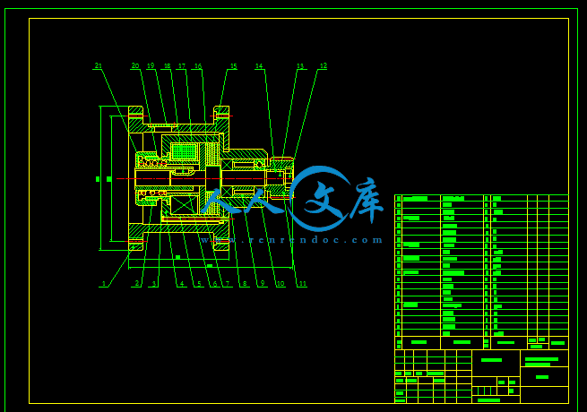
制动器.dwg
外文翻译--组合机CAD系统开发与究.doc
开靠模攻丝组合机床设计题报告.doc
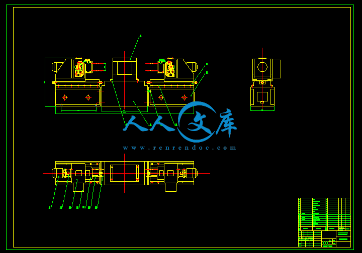
总装图.dwg
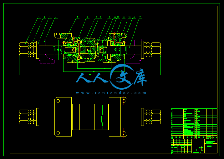
攻丝靠模装配图.dwg
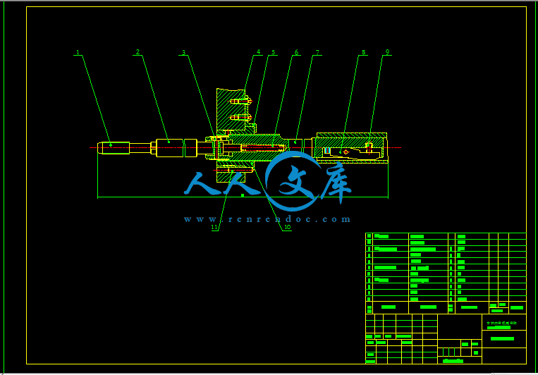
液压滑台部件图.dwg
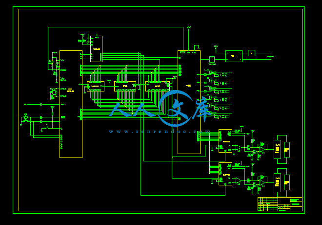
电路图.dwg
靠模攻丝组合机床设计说明书.doc
目 录
1 绪论1
2 设计任务书2
2.1 产品用途和使用范围3
2.2 关于机床的主要加工功能和系统组成的建议3
2.3 关于总体布局的建议4
2.4 主要技术指标和相关重要参数4
2.5 主要工作原理4
2.6 国内外的现状和发展趋势5
2.7 国内外同类产品对比7
2.8 关于采用新技术、新结构、新材料、新工艺的建议7
2.9 拟采用的技术路线7
3 组合机床的总体设计7
3.1 组合机床的配置形式7
3.2 机床加工示意图11
3.3 机床的联系尺寸11
4 组合机床通用部件及其选用13
4.1 攻丝靠模装置和攻丝卡头13
4.2 攻丝装置及攻丝靠模头14
4.3 主轴箱的设计15
5 进给机构的设计19
6 电气部分设计20
6.1 整个机床的动作顺序20
6.2 电器原理图20
总 结23
致 谢24
参考文献25
附录127
附录229
中文摘要
本文是关于双面卧式攻丝机床设计的说明。此机床要求:在两个面同时进行自动攻丝。
本文主要内容包括设计的必要性分析;通过对设计的机床的功能分解与功能合成,以及对方案的设计从而提出新的加工方案。通过对定位方式的选择和对工件工艺性的分析,以及对零件工序图、加工示意图、机床联系尺寸图和功率计算卡这“三卡一图”的分析,提出对组合机床的总体设计方案。文中对组合机床的通用部件及专用部件的选择都做了较为详细的说明。由于要实现自动化,所以对液压传动系统和单片机的电气控制系统的设计显得尤为重要,本文也对此做了阐明,并编写了程序。另外,本文还对设计做了小结。
关键词 组合机床,攻丝,单片机。
组合机床是由通用部件及专用部件组成的,加工一种(或几种)零件的一道或(几道)工序的高效率的专用机床,它的通用部件和标准件约占70%-80%,其余20%-30%的专用部件是由被加工零件的形状、轮廓尺寸、工艺和工序决定,如夹具、主轴箱、刀具和工具等。组合机床一般采用多轴、多刀、多工序、多面、多工位同时加工,是一种工序集中的高效率机床,是一种自动化或半自动化的机床。
组合机床有大型和小型两种。此次设计的攻丝组合机床为大型组合机床。大型组合机床的配置形式主要有两种:⒈具有固定式夹具机床;⒉夹具移动的机床。其中固定式夹具的机床按加工所需的动力头数量及其安装方式可分为:⒈卧式;⒉立式;⒊倾斜式;⒋符合式。夹具移动的机床按夹具的运动方式及立柱形式可分为:⒈往复移动式;⒉回转式;⒊鼓轮式;⒋中央立柱式。本次设计的组合机床为具有固定工作台的卧式双面攻丝组合机床。 产品用途和使用范围
攻丝组合机床是零件生产线上的专用加工设备,并且与零件输送线配套连接工作。本次设计的攻丝组合机床是专用于加工工件两侧面的螺纹孔。
2.2 关于机床的主要加工功能和系统组成的建议
本次设计的攻丝组合机床要加工M10×2.5-16 M6×1.5-8两种螺纹孔,所有螺纹孔在同一工位加工,故采用卧式双面攻丝组合机床来加工被加工工件两侧面的螺纹孔,工件的进给运动由液压传动实现,通过单片机来实现开,停控制。攻丝在主轴的旋转由步进电机和齿轮传动实现,同样是通过单片机控制来实现步进电机的起,停控制和电机的调速。主要技术指标和相关重要参数
生产技术节拍:2分钟/件
位置精度要求:Φ0.3
最大加工直径:M10
2.5 主要工作原理
机床动作顺序:当工件装夹完毕后,按下启动开关,前后攻丝装置沿滑台快速进给,接近工件时,慢进,然后碰到死挡块停止进给,启动攻丝机构,开始攻丝,待攻丝完毕后,丝锥反转退出,紧接着攻丝装置快速退回到原始位置,完成一个加工循环。
- 内容简介:
-
吉林大学本科毕业设计说明书中文摘要本文是关于双面卧式攻丝机床设计的说明。此机床要求:在两个面同时进行自动攻丝。本文主要内容包括设计的必要性分析;通过对设计的机床的功能分解与功能合成,以及对方案的设计从而提出新的加工方案。通过对定位方式的选择和对工件工艺性的分析,以及对零件工序图、加工示意图、机床联系尺寸图和功率计算卡这“三卡一图”的分析,提出对组合机床的总体设计方案。文中对组合机床的通用部件及专用部件的选择都做了较为详细的说明。由于要实现自动化,所以对液压传动系统和单片机的电气控制系统的设计显得尤为重要,本文也对此做了阐明,并编写了程序。另外,本文还对设计做了小结。关键词 组合机床,攻丝,单片机。AbstractThis text is concerning two-lyings offend the silk combination machine bed design of say. The design request of this machine bed is: proceed at the same time in two the auto offend the silk.The main contents in this text includes the necessity analysis of the design; The function that pass the machine to design to bed resolves to synthesize with function, and the design of the other party case from but put forward to process the project newly. Pass to the choiceof the fixed method with to work an analysis for craft analysis, and to spare parts work preface diagram, processing sketch map, machine bed contact size diagram with power calculation stucking “three figures and one card”, put forword to the total design project of the combination machine bed. The text inside all did to the in general use parts of the combination bed and the choice of the appropriation parts than for expatiation. Because of realizing automation, so press to spread to move the system to the liquid to control with the electricity of SCM the design of the system seems to be particularly for importance, this text also makes to clarify to this, writing the procedure. Moreover, this text returns to this time designed to make the sub-footing.Key phrase Combination machine bed, offend the silk,SCM.目 录1 绪论12 设计任务书22.1 产品用途和使用范围22.2 关于机床的主要加工功能和系统组成的建议22.3 关于总体布局的建议32.4 主要技术指标和相关重要参数42.5 主要工作原理42.6 国内外的现状和发展趋势42.7 国内外同类产品对比62.8 跟题目有关的专利情况62.9 关于采用新技术、新结构、新材料、新工艺的建议82.10 拟采用的技术路线83 组合机床的总体设计93.1 组合机床的配置形式93.2 机床加工示意图123.3 机床的联系尺寸124 组合机床通用部件及其选用144.1 攻丝靠模装置和攻丝卡头144.2 攻丝装置及攻丝靠模头154.3 主轴箱的设计165 进给机构的设计206 电气部分设计216.1 整个机床的动作顺序216.2 电器原理图21总 结24致 谢25参考文献26附录128附录230外文资料The aggregate machine-tool CAD system development and research Abstract aggregate machine-tool CAD is in Window 95/98, Wndows under the NT4.0 environment, designs personnels special-purpose CAD system with VC5.0 and the AutoCAD R14 ADS/ARX technology development face the aggregate machine-tool.This software technological advance, performance reliable, function strong, convenient practical, has provided the modernized design tool for our country aggregate machine-tool profession.Key word: Aggregate machine-tool CAD jig CAD multi-axle-box CAD1 uses the aggregate machine-tool CAD technology imperativeThe aggregate machine-tool is with according to serialized, the standardized design general part and the special purpose machine which composes according to the work piece shape and the processing technological requirement design special-purpose part, belongs to the disposable design, the disposable manufacture piecework product.Therefore, the design quantity is big, the design work is complex.In the current competition intense market economy, the user to the engine bed technical sophistication, the quality reliability as well as the goods supply cycle all requests very high, but guaranteed these many factors the key is the design. In the past that backward manual design method has not been able to satisfy the product design the request, uses the CAD technology, throws off the chart board, has become the current technological revolution the tidal current, imperative.2 aggregate machine-tool CAD the application present situation Overseas aggregate machine-tool CAD technology research starts the comparison early.At the beginning of the 70s, some industry developed country first starts in the multi-axle-box CAD aspect to study. Has entered since in particular for the 90s, along with the computer technology development, the interactive cartography and the database management system and so on the development and the application, causes the aggregate machine-tool CAD technology day by day practical also the use scope expands unceasingly, the developed country has used the CAD technology generally in the aggregate machine-tool design.At present, to CAD/CAM integrative system development. In recent years, according to us to American several main engine bed factories (BURGMAST, KINGSBURY, companies and so on INGERSOLL LAMB, CINCINNATI, MILACRON, CROSS) the understanding, its CAD technology obtained the universal application. In which most noticeable is INGERSOLL Corporation has 50 interactive CAD workstation composition software and hardware environment, caused it to realize nearly 100% CAD. On the domestic machine tool design portfolio using CAD understanding earlier. The beginning of the 1970s, Dalian Machine Tool Institute portfolio started on the research in this area of work. 1978 state as a combination of mechanical CAD machine industrial projects, and instructed the Shanghai Jiaotong University. Dalian Machine Tool Institute portfolio, a ministry official in charge of the Institute of Automation, Dalian Polytechnic University, Qinghua University, Beijing University of Technology, Shanghai Institute of mechanical and electrical products and other units to participate in the drilling machine CAD combination of research, This raised our portfolio Machine CAD technology in the district. After 10 years of efforts and achieved initial results. However, the combination of machine CAD system is 12-27 in VAX II and Micro VAX II on the development, hardware investment, which is difficult to use. By the time the hardware and software environment for the restrictions, narrow scope of application software, users inconvenient.3 Development portfolio dedicated machine CAD system software CAD technology is the contemporary electronic information technology an important component of , CAD technology to be commercialized as the most important high-tech industries. The supporting software and hardware, on the basis of different industries, different professions secondary development software, developed for the industry, The dedicated professional commercial software can not only make good economic returns, but will make significant social benefits. Ninth Five-Year Plan period state auto industry as a pillar industry of the national economy, for the industry to provide a combination of technologies and equipment to machine tool industry to develop rapidly. Along with the development of the auto industry, machine designed to enhance portfolio quality, shorten the design cycle has become an extremely urgent task. Combined Machine CAD technology and can shorten the design cycle and improve design quality, enterprises in the sector improve its competitive edge, enterprises will bring about significant economic benefits. Dalian is Chinas important industrial base, as a combination of Machine Tool Industry Technology and Development Center in Dalian Machine Tool Institute portfolio, industry should play the leading role for the realization of design automation, enhance technological innovation and product competitiveness. promoting our portfolio machine design standards, as soon as possible combination of machine tool industry to provide factory-functional, flexible operation, with a friendly interface, high technological content portfolio Machine CAD software.4 software with the technical basis for the development of microelectronics Technology, computer performance has been greatly improved. P II has now dominated the market, P III began listing its CPU performance has been close to the years before the target workstation. Foreign CAD software to the PC Window95/98, Windows NT transplant, such as Pro / Engineer, I-Sui, such as CADDS5. Computer Graphics Accelerator in improving performance, the entity can basically the movement and rotation. PC CAD is a development direction, the corresponding hardware to lower than many workstations. After years of efforts, we use Windows SDK software development technology, Windows environment more dynamic process of technical data exchange (DDE). Database technique (ODBC), Graphics software technology and the development of secondary targets OLE technology (OLE), Development of a generic combination of mechanical CAD and CAD machine integrated CAD system. 5 Combination Machine CAD system software Portfolio Machine CAD system software using C + + language, in the Windows environment for the development of the combination of machine design parameters of the graphic information management system. Database systems with C + + language independent preparation of the financial database software and operating system parameters graphic systems into one. formed powerful parametric graphic information management system. Modular Machine CAD system including removable fixture CAD system, Modular Machine Automatic Line program 3D CAD graphics system, the total portfolio Machine CAD system, Portfolio Map Machine CAD systems and machine tools multi-axle box CAD system. 5.1 Combination fixture mechanical CAD system using parametric CAD graphics information management technology and interactive design methods, developed portfolio fixture CAD system, its widespread applicability, practical and promote the use of broad prospects. Combination fixture CAD system, in accordance with its main functions can be divided into four modules : Location Support System CAD system, Clamping CAD system, CAD-oriented systems and devices typical fixture clamping force of the computer-aided analysis and calculation. 5.1.1 Location Support System CAD systems for supporting the system by positioning support, Auxiliary support and spacing element composition. Location Support refers to the processing maintain a certain position workpiece components; Auxiliary support is only for the processing of the rigidity and stability of an activity-supporting components. Building support plate, supporting block, ancillary support, fixed-pin, telescopic pin parametric graphics library and database performance through inquiries Location Support System database, Positioning support amending parameters graphic parameters, the use of interactive design method, positioning support CAD system. 5.1.2 clamping CAD system clamping usually by clamping force, Transmission among agencies and clamping element is composed of three parts. Part of clamping force for the purpose of generating power source, and will pass on the middle forces drive; Middle drive as a Force that is, to change the direction of force and size, which can produce self-locking, to ensure that the processing power source or disappeared, the role of the workpiece in the cutting force despite reliable clamping; Clamping elements to bear by the middle of the drive transmission clamping force, and direct contact with the workpiece clamping action and implementation. Clamping established tank, clamping components, direct clamping bodies, self-locking clamping mechanism parameters of the graphics and performance database, Clamping inquiries by the Performance database changes clamping mechanism parameters graphic parameters, the use of interactive design, Clamping achieve CAD. 5.1.3 device-oriented CAD system installation guide role is to ensure that the tool and workpiece and the tool of inter - The exact location, raising tool system supports rigid. Correct selection, design-oriented devices, assurance of the accuracy and processing of reliable machine plays an important role in the work. Establish a fixed-oriented packages, roll-forward - oriented devices, , roll-forward device parameters oriented graphics library and database performance through inquiry-oriented device performance database, revised guidance device parameters graphic parameters, the use of interactive design method, CAD-oriented devices. 5.1.4 typical fixture clamping force computer-aided analysis and calculation of the machine to ensure normal reliable working conditions, the clamping force the smaller the better. If blindly increasing the clamping force, which will result in the following consequences : increased fixture drive size; To improve clamping force and linked to the fixture so rigid fixture is too big; increase the clamping of the workpiece in the deformation and effects processing accuracy. Therefore, the right to determine clamping force is important. Typical fixture clamping force computer-aided analysis and calculation : the clamping screw clamping force analysis and calculation Wedge Clamp the clamping force analysis and calculation, the eccentric clamping clamping force analysis and calculation Clamping other agencies clamping force analysis and calculation. Combination fixture interactive CAD system design methods, the use of flexible, widespread applicability, meet all the technical requirements. Fixture system through the establishment of various components of the graphics library, parts of the parameters of graphics library, Parameter graphics information management system, interactive mapping portfolio fixture. 5.2 Combination Machine automatic alignment options CAD 3D graphics system, the total portfolio Machine CAD system, Portfolio Map Machine CAD System 5.2.1 portfolio automatic alignment machine 3D graphics CAD System The CAD system can automatically determine portfolio machine line, drawing portfolio machine automatically 3D graphics, Universal Machine portfolio management structure and performance parts database. This three part by the three independent process to achieve, Using Windows environment more dynamic process of technical data exchange (DDE). achieving three independent process dynamic data exchange, completed the following types of machine configuration combinations Machine Design : more horizontal axle box processing, multi-axle box vertical machining, multi-axle box tilt-processing, the first Horizontal Boring processing, Boring first vertical machining, boring head tilted machining, drilling the first horizontal machining, drilling the first vertical machining, Drilling of the first tilt-processing, tapping the first horizontal machining, the first vertical machining tapping, tapping the first tilt-processing, Milling of the first horizontal machining, milling head vertical machining, milling machining head tilt. 5.2.2 total portfolio Machine CAD system map total portfolio machine with automatic computer-aided design and human-computer design interactive design methods. Automatic design of the structure from the program to map out the final completion of a one-time, interactive design is user participation, choice of interactive components, models and determine a method of positioning. Combination machine is used by the serialization, standardized generic components and by the shape of the workpiece and the processing requirements of the dedicated parts of dedicated machine, thus Machine features that determine its computer-aided design methods. Its versatility to be completed by the computer, and a dedicated help from computer users to achieve, that is, to avoid the automatic design of the applicability of poor, narrow face design limitations. Total portfolio machine parameters graphic information management system in Windows development environment of a human-machine interactive located Total system, which integrates the Windows SDK technology, Database technology and graphics software secondary development of the ADS technology, engineering design provides a very convenient, Efficient design of the machine tool map. The system is suitable for drilling, expansion joints, and tasty, boring, milling, etc. Tapping Machine processing, machine configuration form of single-position reclining, Li, tilt and composite portfolio machine, mobile work desktop machine combinations, combinations Rotary desktop machine. 5.2.3 Combination Machine CAD system portfolio Map Machine Tool schematic design and adjustment team Machine for the important work of one of the drawings, is to identify combinations machine linked size, composition Machine Drawing the basis for the total. To accomplish drilling and reaming, boring, Reaming, Tapping and milling processes. Portfolio machining complex matrix. According to the development of the last 10 years combined experience in the CAD machine, the automated design, only a few input parameters will be completed portfolio Machining Map software, but the application of the matrix of small, have limitations. Combination Machine Map parameters graphic information management system software, interactive design, the use of flexible, widespread applicability, meet all the technical requirements. Combination Machine Map parameters graphic information management system from the main spindle and then leverage, the guidance sets, Tool database operating systems, the operating system parameters graphics, Interactive mapping system to determine composition and cutting machine usage module four components. Axlebox over 5.3 CAD system more Axlebox CAD system CAD system more Axlebox CAD system is a specialized application software can be used for drilling and expansion. hinges, milling, drilling and thread offensive attack composite portfolio Machine Tool box design. System for the raw data from the combination of machine design, a plan that is three cards (workpiece map, processing matrix, Machine size map and the associated productivity calculation card), such as spindle coordinates, speed, and on this basis, interactive system to automatically or engaging in various types of work. 5.3.1 Multi-axle box drive system design combination Multi-axle box drive system design combination of multi-axle box machine drive system is a multi-axis, multi-gear, Multi-time complex transmission system. We have adopted a two-axis, three-axis drive, the basic methodology Transmission is the formation of the two basic methods of connecting continuously portfolio called. The complete transmission module coordinates, various geometric interference checking, transmission components strength check. To achieve optimum transmission purposes (minimum number of drive shaft, gear minimal number), using the following design, as illustrated in figure 1, as shown in Figure 2. Figure 1 2 shaft gear design Figure 2 triaxial Gear Design Optimization Optimization0 - gear shaft has 0 - have gear shaft 1 - the new design Gear 1 - Design new gear 6 Portfolio Machine CAD software operating environment Software operating environment for the hardware : CPU 486 more, Memory 16 M over all software required disk space 350 M above. Software running the software environment : Windows 95/98, Windows NT 4.0, AutoCAD R14.0 7 Portfolio Machine CAD software has been approved by experts and has a market push 1998The combination of machine CAD software approved by experts. The software technology advanced, reliable performance, strong function, convenient and practical. China machine tool industry portfolio provides a modern design tools, the technology level of a leading position at home. The software has been designed in modular machine tool manufacturing plant and the professional engaged in internal-combustion engines, Engine production of large and medium-sized enterprises in the design and manufacture of modular machine tool sector wider application. Constant portfolio such as Jiangsu Machine Co., the second machine factory in Baoding, Diesel Co., Shandong Huayuan Levin move Engine Company Limited. Enterprises in the transformation of traditional industries, through the use of CAD technology, the electronic play of the power of information technology, improve the design level, and enhance the companys ability to create and product competitiveness, achieved good economic and social benefits. 中文译文组合机床CAD系统开发与研究1采用组合机床CAD技术势在必行组合机床是用按系列化、标准化设计的通用部件和按工件的形状及加工工艺要求设计的专用部件组成的专用机床,属于一次性设计、一次性制造的单件生产产品。因此,设计量大,设计工作复杂。在当前竞争激烈的市场经济中,用户对机床的技术先进性、质量可靠性以及供货周期都要求很高,而保证这诸多因素的关键是设计。过去那种落后的手工设计方法已不能满足产品设计的要求,采用CAD技术,甩掉图板,已成为当前技术革命的潮流,势在必行。2组合机床CAD应用现状国外组合机床CAD技术的研究开始得比较早。70年代初,一些工业发达国家首先在多轴箱CAD方面开始研究。尤其是进入90年代以来,随着计算机技术的发展,交互式绘图和数据库管理系统等的发展和应用,使组合机床CAD技术日益实用且使用范围不断扩大,发达国家在组合机床设计中已普遍采用了CAD技术。目前,正在向CAD/CAM集成系统发展。近年来,据我们对美国几个主要机床厂家(BURGMAST、KINGSBURY、INGERSOLL LAMB、CINCINNATI、MILACRON、CROSS等公司)的了解,其CAD技术已得到普遍应用。其中最引人注目的是INGERSOLL公司具有50个交互式CAD工作站组成的软、硬件环境,使其实现了几乎百分之百的CAD化。国内对组合机床设计采用CAD的认识也比较早。70年代初,大连组合机床研究所就开始了这方面的研究工作。1978年国家把组合机床CAD列为机械工业重点项目,并责成上海交通大学、大连组合机床研究所、机械部自动化研究所负责,大连理工大学、清华大学、北京工业大学、上海机电产品研究院等单位参加,对钻孔组合机床CAD进行了研究,从此揭开了我国组合机床CAD技术的序幕。经过十多年的努力,取得了初步成果。但是,组合机床CAD系统是在VAX-750和Micro VAX上开发的,硬件投资大,不易于推广应用。受当时硬件条件及软件环境的限制,软件适用范围窄,用户使用不方便。3开发组合机床CAD系统专用软件CAD技术是当代电子信息技术的重要组成部分,CAD技术商品化应作为高新技术产业中重中之重。在支撑软件和硬件的基础上,针对不同行业、不同专业进行软件二次开发,开发出适合本行业、本专业的专用商品化软件,不仅可以取得良好的经济效益,而且会取得重大的社会效益。“九五”期间国家把汽车工业作为国民经济的支柱产业,给汽车工业提供技术装备的组合机床行业得以迅速发展。随着汽车工业的发展,提高组合机床设计质量、缩短设计周期便成为极其迫切的任务。采用组合机床CAD技术,能缩短设计周期,提高产品设计质量,提高企业在行业中的竞争力,给企业带来显著的经济效益。大连是我国重要的工业基地,作为组合机床行业科技开发中心的大连组合机床研究所,应当发挥行业的主导作用,为实现设计自动化、增强企业技术创新能力和产品竞争能力,推动我国组合机床设计水平,尽快向组合机床行业厂提供功能强、操作灵活、界面友好、技术含量高的组合机床CAD软件。4开发软件的技术基础随着微电子技术的发展,微机的性能有了很大的提高。现在P已经主导市场,P开始上市,其CPU性能指标已接近几年前的工作站指标。国外CAD软件向微机的Window95/98、Windows NT上移植,如Pro/Engineer、-DEAS、CADDS5等。微机的图形加速卡性能在提高,基本上能进行实体的移动和旋转。微机CAD是一个发展方向,相应的硬件比工作站要降低很多。经过几年的努力,我们利用Windows的SDK软件开发技术、Windows环境下多进程间的动态数据交换技术(DDE)、数据库操作技术(ODBC)、图形软件二次开发技术及目标链接与嵌入技术(OLE),开发了集通用机械CAD和组合机床CAD于一体的CAD集成系统。5组合机床CAD系统软件组合机床CAD系统软件采用C语言,在Windows环境下开发的面向组合机床设计人员的参数化图形信息管理系统。数据库系统用C语言独立编写,本软件融数据库操作系统和参数化图形系统于一体,形成功能强大的参数化图形信息管理系统。组合机床CAD系统包括组合机床夹具CAD系统、组合机床自动线方案三维图形CAD系统、组合机床总图CAD系统、组合机床加工示意图CAD系统和组合机床多轴箱CAD系统。5.1组合机床夹具CAD系统利用机械CAD参数化图形信息管理技术和交互设计方法,开发组合机床夹具CAD系统,其适用面广、实用性强、推广应用前景广阔。组合机床夹具CAD系统按照其主要功能可分为四大模块:定位支撑系统CAD系统、夹紧机构CAD系统、导向装置CAD系统和典型夹具夹紧力的计算机辅助分析与计算。5.1.1定位支撑系统CAD系统定位支撑系统主要由定位支撑、辅助支撑和限位元件组成。定位支撑是指在加工过程中维持工件有一定位置的元件;辅助支撑是仅用作加工过程中的刚度及稳定性的一种活动式支撑元件。建立支撑板、支撑块、辅助支撑、固定式定位销、伸缩式定位销参数化图形库及其性能数据库,通过查询定位支撑系统性能数据库、修改定位支撑参数化图形参数,利用交互设计方法,实现定位支撑系统CAD。5.1.2夹紧机构CAD系统夹紧机构通常由夹紧力部分、中间传动机构和夹紧元件三部分组成。夹紧力部分用于产生动力源,并将作用力传给中间传动机构;中间传动机构即作为增力机构,能改变作用力的方向和大小,能产生自锁作用,以保证在加工过程中或动力源消失时,工件在切削力作用下仍能可靠夹紧;
- 温馨提示:
1: 本站所有资源如无特殊说明,都需要本地电脑安装OFFICE2007和PDF阅读器。图纸软件为CAD,CAXA,PROE,UG,SolidWorks等.压缩文件请下载最新的WinRAR软件解压。
2: 本站的文档不包含任何第三方提供的附件图纸等,如果需要附件,请联系上传者。文件的所有权益归上传用户所有。
3.本站RAR压缩包中若带图纸,网页内容里面会有图纸预览,若没有图纸预览就没有图纸。
4. 未经权益所有人同意不得将文件中的内容挪作商业或盈利用途。
5. 人人文库网仅提供信息存储空间,仅对用户上传内容的表现方式做保护处理,对用户上传分享的文档内容本身不做任何修改或编辑,并不能对任何下载内容负责。
6. 下载文件中如有侵权或不适当内容,请与我们联系,我们立即纠正。
7. 本站不保证下载资源的准确性、安全性和完整性, 同时也不承担用户因使用这些下载资源对自己和他人造成任何形式的伤害或损失。

人人文库网所有资源均是用户自行上传分享,仅供网友学习交流,未经上传用户书面授权,请勿作他用。
 川公网安备: 51019002004831号