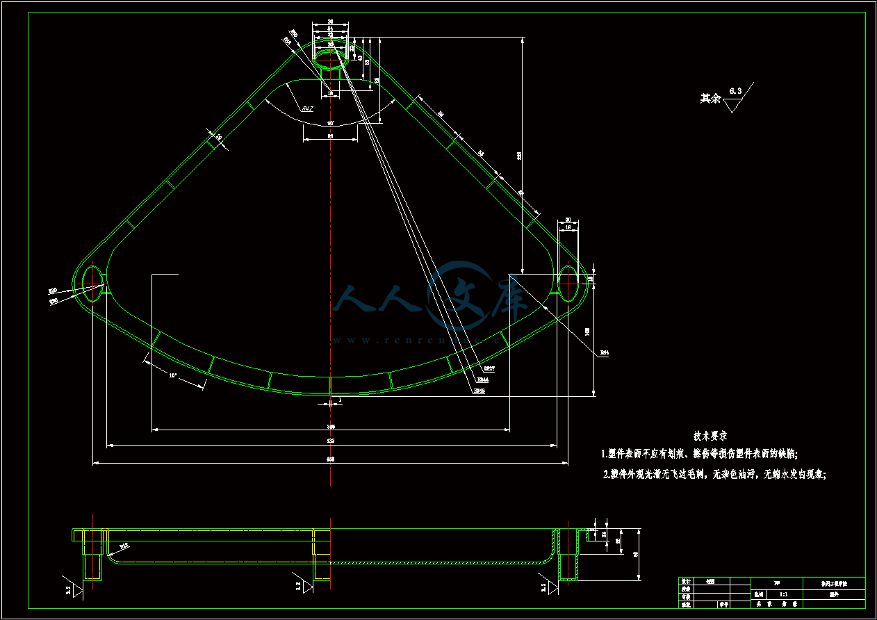
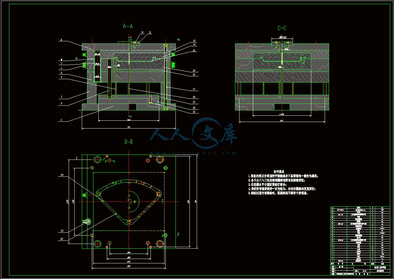
装配图.dwg
装配图.dwg

多用角架搁板的注塑模具设计及其仿真加工设计【9张图纸】【优秀】

收藏

资源目录
跳过导航链接。
压缩包内文档预览:
预览图
编号:420515    类型:共享资源    大小:3.31MB    格式:RAR    上传时间:2015-03-29 上传人:上*** IP属地:江苏
39
积分
关 键 词:
多用 角架搁板 注塑 模具设计 及其 仿真加工 设计 图纸 多用角架搁板
资源描述:

多用角架搁板的注塑模具设计及其仿真加工设计

50页 21000字数+说明书+外文翻译+9张CAD图纸【详情如下】

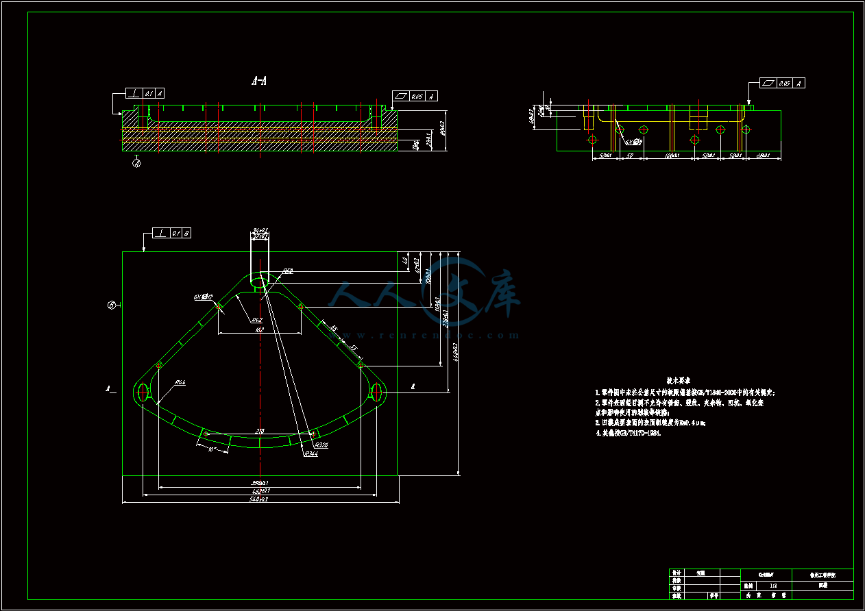
凸模.dwg

凹模.dwg

动模固定板.dwg

塑件.dwg

外文翻译--对通过塑料注射成型零件的选择性激光融化生产得到的功能梯度材料插入棒的评估 中文版.doc

外文翻译--对通过塑料注射成型零件的选择性激光融化生产得到的功能梯度材料插入棒的评估 英文版.pdf

多用角架搁板.doc

多用角架搁板的注塑模具设计及其仿真加工设计.doc

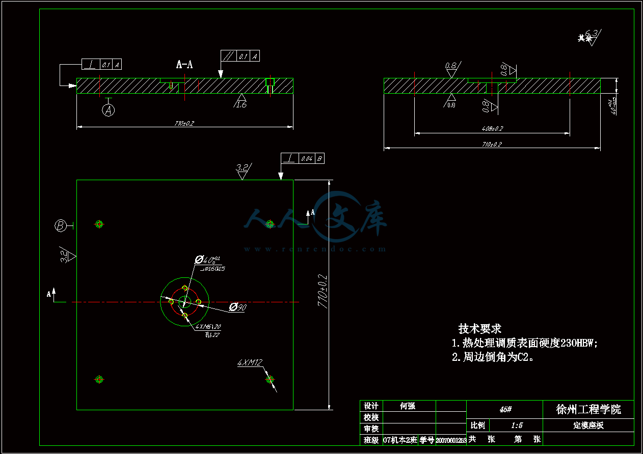
定模座板.dwg

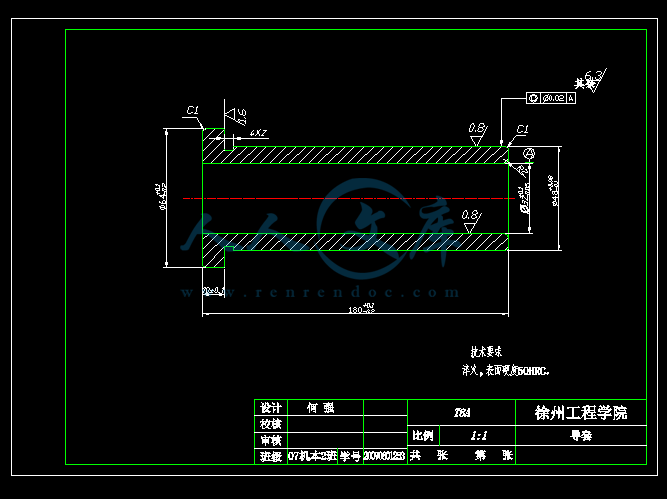
导套.dwg

拉料杆A4.dwg

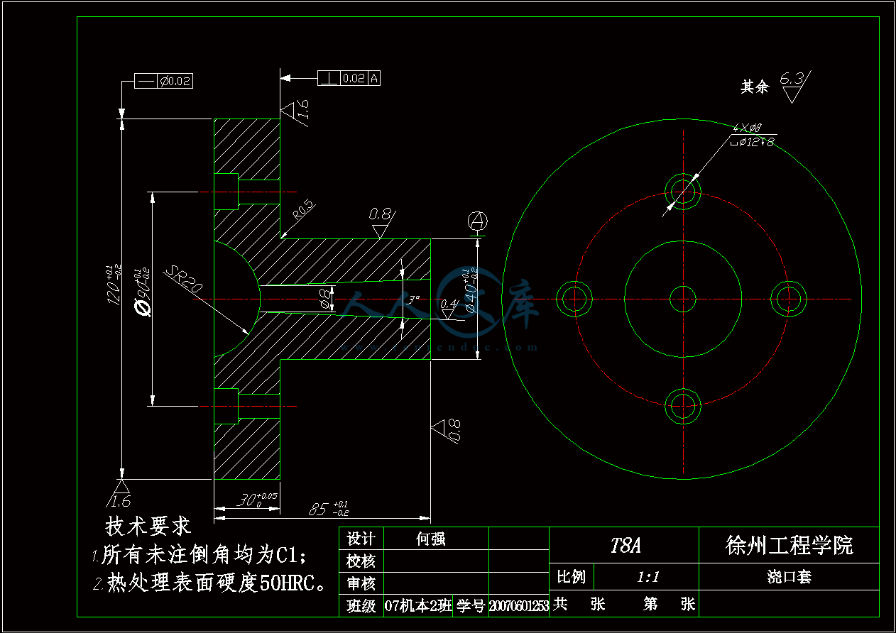
浇口套.dwg

装配图.dwg

目录

摘要I

AbstractII

1 绪论1

1.1模具工业的地位和发展前景1

1.2课题内容和意义1

2塑件成型工艺性分析3

2.1塑件结构分析3

2.2塑件的工艺性分析3

2.2.1塑件材料的选择3

2.2.2 塑件的壁厚5

2.2.3 塑件的表面质量5

2.2.4 塑件的精度等级6

2.2.5 塑件的脱模斜度6

2.3 PP塑件的注射工艺7

3 分型面的选择9

3.1 分型面位置的确定9

3.2 型腔数目的确定10

4 注射机型号的选择11

4.1 体积质量的计算11

4.2 注射机的选择11

4.3 注射机相关参数的校核12

5 注射过程与模流分析14

5.1 MoldFlow分析软件简介14

5.2 网格划分14

5.3 塑件的最佳浇口位置分析15

5.4 塑件的流动性分析16

5.4.1 气穴和熔接痕16

5.4.2 注射位置处压力17

5.4.3充填时间17

5.4.4 锁模力18

5.5塑件的冷却分析18

5.6 MoldFlow分析总结19

6 浇注系统的设计20

6.1 浇注系统的设计原则20

6.2 主流道的设计和计算20

6.3 浇口的设计21

6.4校核主流道的剪切速率21

7注塑模具成型零件及模具体的设计22

7.1成型零件的结构设计22

7.2成型零件钢材的选用22

7.3成型零件工作尺寸的计算22

7.3.1凹模径向尺寸的计算22

7.3.2凹模深度尺寸的计算23

7.3.3凸模径向尺寸的计算23

7.3.4 凸模高度尺寸的计算23

7.4 合模导向机构的设计23

7.5 脱模机构的设计24

7.5.1脱模力的计算24

7.5.2塑件脱出机构25

7.6 模架的确定26

7.7模架各尺寸的校核26

8冷却系统及排气系统设计27

8.1 冷却系统的设计27

8.1.1 模具温度调节的必要性27

8.1.2 冷却系统的设计原则27

8.1.3 冷却水道的设计27

8.2排气和引气系统的设计29

9模具的装配与调试31

10 基于Mastercam X2的仿真加工33

10.1 Mastercam X2软件简介33

10.2 多用角架搁板凸模加工34

10.2.1 加工坯料及对刀点的确定34

10.2.2规划曲面挖槽粗加工刀具路径34

10.2.3 工件参数设置35

10.2.4 曲面挖槽粗加工实体加工模拟35

10.2.5规划分型面浅平面精加工刀具路径36

10.2.6分型面浅平面精加工实体加工模拟36

10.2.7规划等高外形精加工刀具路径37

10.2.8 曲面等高外形精加工实体加工模拟37

10.2.9 规划3圆鼻刀曲面平行精加工刀具路径38

10.2.10曲面平行精加工实体加工模拟39

10.2.11 规划顶面平行铣削精加工刀具路径39

10.2.12 顶面平行铣削精加工平行铣削实体加工模拟40

10.3生成加工NC代码40

结论42

致谢43

参考文献44

摘要

   注射模具是模具工业的重要发展方向,也是衡量一个国家产品制造水平高低的重要标志。模具 CAD/CAE/CAM 技术的应用从根本上改变了传统的产品开发和模具生产方式,大大提高了生产效率、产品品质以及企业自身的竞争力。

   本文根据多用角架搁板实物模型进行了模型特征重构,在此基础上基于 PRO/E软件设计出一套合理的注射模具。首先分析了多用角架搁板制件的工艺特点,包括材料性能、结构工艺性、成型特性与条件等,并选择了成型设备。然后介绍了香皂盒注射模的分型面选择、型腔数目及布置形式,重点介绍了浇注系统、成型零件、冷却系统、脱模机构的设计。然后选择模架,并对注射机的工艺参数进行了校核。在此基础上,本文讲诉了如何运用Mastercam软件对多用角架搁板凸模进行仿真加工。  

关键词 注射模具;PRO/E;Mastercam;仿真加工

1 绪论

1.1模具工业的地位和发展前景

塑料注射成型所用的模具称为注射成型模,简称注射模。它是实现注射成型工艺的重要工艺装备。塑料模具为模具总量近 40%,而且这个比例还在不断上升。这类模具主要是两类:一类是大型模具,一类是精密模具。大型模具主要是以汽车仪表板,保险杠和家电产品模具为代表的成型模具。精密模具是以集成电路、塑封模具为代表的成型模具。注射模具被欧美等发达国家誉为“磁力工业”。很大部分工业产品依赖注射模具才得以规模生产、快速扩张,由于注射模具对社会生产和国民经济的巨大推动作用和自身的高附加值,世界模具工业,尤其是注射模具工业发展较快,当前全球模具工业的产值已经达到 600 亿~650 亿美元,是机床工业产值的两倍,其中注射模具工业的产值已经达到 240 亿至 260 亿 。

纵观发达国家对模具工业的认识与重视,我们感受到制造理念陈旧则是我国模具工业发展滞后的直接原因。模具技术水平的高低,决定着产品的质量、效益和新产品开发能力,它已成为衡量一个国家制造业水平高低的重要标志。因此,模具是国家重点鼓励与支持发展的技术和产品,现代模具是多学科知识集聚的高新技术产业的一部分,是国民经济的装备产业,其技术、资金与劳动相对密集。目前,我国模具工业的当务之急是加快技术进步,调整产品结构,增加高档模具的比重,质中求效益,提高模具的国产化程度,减少对进口模具的依赖。

现代模具技术的发展,在很大程度上依赖于模具标准化、优质模具材料的研究、先进的设计与制造技术、专用的机床设备,更重要的是生产技术的管理等。21世纪模具行业的基本特征是高度集成化、智能化、柔性化和网络化。追求的目标是提高产品的质量及生产效率,缩短设计及制造周期,降低生产成本,最大限度地提高模具行业的应变能力,满足用户需要。

在科技发展中,人是第一因素,因此我们要特别注重人才的培养,实现产、学、研相结合,培养更多的模具人才,搞好技术创新,提高模具设计制造水平。在制造中积极采用多媒体与虚拟现实技术,逐步走向网络化、智能化环境,实现模具企业的敏捷制造、动态联盟与系统集成。我国模具工业一个完全信息化的、充满着朝气和希望而又实实在在的新时代即将到来。

1.2课题内容和意义

本次设计的课题设计内容主要包括以下几点:

1.进行多用角架搁板塑件的三维造型设计;

2.从塑料品种、塑件形状、尺寸精度、表面粗糙度等方面考虑注塑成型工艺的可行性和经济性,进行塑件成型的工艺性分析;

3.根据塑件的质量和模具型腔数大致确定模具的结构,初步确定注射机型号,了解注射机与模具有关的技术参数;

4.考虑塑件成型位置及分型面选择,模具型腔数,型腔的排列,流道布局及浇口位置设置来进行凸、凹模零件设计;

5.将模具三维模型导入CAM软件中,进行注塑成型模具三维型面的数控仿真加工;

6.由模具三维结构图绘制出二维装配图,依据装配图完成模具主要零件的设计和图样绘制。

本次毕业设计通过对注塑成型模具的设计,可了解常用塑料的性能、塑料制品的设计原则及方法,掌握注射模具常用结构的组成、特点及应用场合,并由此熟悉注射成型工艺及仿真加工的全过程。通过学习现代化的设计制造方法,积极开展CAD/CAM技术在注射模具设计中的推广应用, 从而提高自己进行模具设计的工作能力。

内容简介:
对通过塑料注射成型零件的选择性激光融化生产得到的功能梯度材料插入棒的评估V E Beal1 ,P Erasenthiran2、C H Ahrens1,P Dickens21.巴西卡特里娜城郊Floriano联邦大学2.英国哈伦大学机械工程学院之母该手稿收于2006年10月19日,修订后于2007年3月9日出版。DOI: 10.1243/09544054JEM764摘要注塑行业对生产率和形状复杂的需求需要新的研究提高工具设计、材料和制造。通过功能梯度结构建立注射模具的发展是其中一个研究领域。例如,具有功能梯度材料建造技术的模具可以获得具有较高导热性的独特部分。厚的注射部件具有较高的热传导率,这有利于生产出更好的和更便宜的聚合物注射模具部件。在以工具钢为原料制造模具的时候加入铜,有可能获得不同传导性的模具。在这篇文章中,我们将为您描述关于功能梯度材料影响的调查-工作分成两部分:一个是Cu分级工具钢和工具钢的插入棒的热数值分析比较和比较聚丙烯部件模具表面温度和结晶度的程度的注射成型试验。数值模型用来根据模具插入材料不同比较模具传热性能。之后,建立了一个支持保持功能梯度材料和工具钢插入棒得到了选择性激光融合的过程。聚丙烯被注射入注塑件中与数值结果进行对比。为了观察分级插入聚丙烯部件的冷却速度,部件的结晶度由差示扫描量热法测量(DSC)测试。也评价了注射周期模具的温度。结果表明,Cu-tool测试评分插筋储仓热量能力较低。工具钢中添加铜的混合钢铁能更有效地传递热量但是吸收热量能力低。关键词:功能梯度材料;注射模具;快速制造;聚丙烯结晶度1 引言注射模具部件的优势取决于三个主要方面:工具成本、注塑模具原料和生产力工具。这三个组合使得在不影响生产力和材料的情况下很难改变部件/模具设计。因此,必须通过最佳的原材料选择和部分件和模具设计获得工具的耐久性、生产力、成本1。不幸的是,有德限制使得很难找到最好的有前途的解决方案。现代注射模复杂性变高,模具设计师的关注是如何孕育不产生部分扭曲的部件,从而保持高水平生产率。一个复杂的渠道网络设计被用来使冷却液体从模具中吸取热量。通道的设计是困难的,因为它必须用来使喷发系统作用。顶出针、投影片和气流门是用来使部件从铸型腔中喷出避免部件审美方面。根据部件的复杂性和形状, 冷却系统留下的空间小, 在模具上不留痕对制造来说并不可行。在许多情况下,当高温均匀提取腔的散热均衡和生产率未达成,重新设计部件几何从而适合模具的局限性是必要的。另一种解决复杂的热问题的方法是使用(Cu-Be)插入1。与一般钢合金相比Cu-Be嵌入会有更高的导热系数、在注射成型周期中,当冷却途径不起作用的时候他们被使用来从冷却通道的地区提取热量。然而,它们不是环保的,铍被引证为是一种致癌因素2。另一限制是因为模具表面基础材料之间有一个明显的联系,模具的插入会在部件上留下痕迹。此外, 需要减少冷却通道空地插入的特性。到了上世纪80年代中期,新的被称为SFF(固体自由形式的制造)的生产技术出现了3。这些技术相对于传统的来说,最主要的区别在于他们是基于层添加剂的原则。也被称为快速成型(RP),这些技术几乎可以用任何形式或材料小批量生产部件。各类可得的资料是有限的,然而,RP过程可以用金属、陶瓷、和聚合物建造零件3。因为机器几乎能从计算机软件生成的数据中制造出坚实的部件,总机技术的自动化程度很高,而且他们也被称为“解决三维技术的打印机”。设计师和工程师可以精确、适当和无误解、没有延迟地建立和验证设计部件。RP技术的基本原理是根据部件设计的数据建立一层一层的材料。原料物质可以为液体树脂、电线、软糖、粉末和床上用品。去形成这些材料的方法是多样的,包括紫外激光、电力激光、喷胶、沉积融合材料等等。这些附加层制造技术(LMTs)也被应用于注塑模具的生产。根据用于建筑工艺及材料、错综复杂的模具槽(注射部分)和注射的材料,这些模具与传统模具相比具有竞争力。根据技术,材料和应用,它可以建造12到一万个部件的模具4,5。用于SFF建立注塑模具的有趣技术是常规的冷却渠道。渠道是在没有考虑传统的制造方法的局限性的情况下在模具中设计的。常规的冷却渠道可以遵循冷却通道模具的表面,与正常模具相比,生产时的引射系统限制较少。不幸的是,由于顶出系统和部件的一些功能,例如深层可能不受渠道散热能力的影响,它们仍然是有限的。为克服这些限制,使得运用SFF技术通过功能梯度结构来建立注塑模具变为可能。在过去的25年里功能梯度材料已经成为研究的问题6。大部分的天然材料,如矿物质和组织逐渐从一个功能区变化到另一个地方。这个自然的例子激发同一个部件/单位的整合模式与功能设计。就生产工艺来说,功能梯度材料并不完全是新的,但是仅仅是20世纪80年代后,它开始被更多的关注并且被分类为一个特定研究主题。功能梯度材料的基本理念是通过丰富特定区域成分来得到不同特性,从而提高部件的质量。这个成份可能是一种基本元素,如碳只能被用来增加钢在表面的硬度。另一个例子就是哺乳动物外面到内侧孔隙度变化的骨头。外面的低孔隙度的刚度增加了他的脑骨,但是提供了到内的联系。骨的核心是多孔性,从而允许重量效率。利用该材料从一处到另一个地方的变化, 可以获得优化组件。减少关节的数量和紧固件,减轻质量,结构提高,微分散热、热屏障,嵌入式传感器,种植生物相容性的使用都是功能梯度材料的潜在优势6-8。功能梯度材料在相同的组成部分也能逐渐加入不同性质的不同材料,原则是与复合材料类似。不同的是,复合材料是一种具有独特的阶段,在改变他们大量各组成部分的成分方面不能行。尽管功能梯度材料的概念非常简单,多数潜在的功能梯度材料的应用由于科技的限制,工程造价高而受到限制。在控制和沉积梯度组成和配合计算机辅助设计(CAD)生产复杂的形状,计算机辅助制造(CAM),FEA(有限元分析)方面的困难都是使用受到限制的部分原因。很多研究人员已经研究了使用技术生产零件 9。因为RP技术可以制造曲面零件,处理不同的材料,可以用他们来生产功能梯度材料。大多的研究人员通过一种激光束提供的热源制备研究LMTs功能梯度材料的形成过程。由于激光器自动化很容易,并能精确和高速度地提供高能量密度,他们几乎可以处理任何材料10。功能梯度材料和RP的另一个方面是材料中经常使用的粉末状或事先融合烧结下的光斑。局部组成控制(LCC)是使用快速生产加工和制造技术生产功能梯度材料零件的主要问题。这方面牵涉到通过控制加入材料的每个部分或层区域的百分比的原则。一些研究者11,12用微型漏斗,喷嘴及毛细管,控制沉积层中的粉末。Ensz等人13在激光网络成型(LENS)梯度工程过程研究了两个粉流的优化来构建H13到M300的钢合金。此外,代表分级几何的计算方法一直是研究的课题。取得了有限元和体素空间几何数据,Cho等人14通过印刷工艺有限责任公司研究了三维几何形状和材料。通过这种方法,有可能用不同的容量梯度来数字化地代表3D零件。 在以前的工作中,已经开始研究向基础材料中增加一个额外的功能性材料来生产出功能梯度材料注塑模具15。一个多室料斗被用来制造梯度结构的H13模具钢和铜。因为H13是尺寸稳定性、韧性好,耐高温磨损的材料,所以是常用的生产注射模具的材料。不过和铜(kH13:24.3瓦/米k,kCu:385瓦/米)相比这种材料的热传导是比较低的16,17。铜元素粉末以12.5,25,37.5,50的比例与H13混合从而得到功能梯度材料棒。这些棒的生产方法是使用高粉的Nd:YAG脉冲激光器来选择激光聚变/熔化(超低频或SLM)。以前用料斗装入多室粉末,现在激光可以加工多成分粉末。当激光扫描粉末,粉融合并吸附在先前添加层上。经处理后作为层,粉层变低,粉末在上一层上铺开,激光用来融合粉末形成一个新的层。对这个过程进行了数值控制,并且继续进行直至完成部件的生产。在融合过程中采用这种激光会留下粗糙的表面,需要一些包括去除被用来吸附的第一层平台的粉末床基质后处理。分级H13和铜零件在该过程结束时可以得到。因此,功能梯度材料可在注塑模具制造中用来形成高导热地区从而提高热伸缩性。由于可制造性和喷射系统,冷却/加热的渠道有限,一些地区的现象可能是过热。部件的不同热收缩率可能导致翘曲,水槽和冷焊接痕迹,表面质量差,而且可以减缓部件生产速度。另一项关于功能梯度材料在模具上的应用是建立了工具钢和硬质合金梯度腔边缘。这可以通过改善诸如模具边缘闪烁磨损造成的缺陷提高零件质量1。运用功能梯度材料获取高性能注塑模具是这种研究的动力之一。尽管在工作中使用激光和层沉积有局限,这些实验计划仍然是用来评估增加铜H13的影响。相较于H13的基础材料,加Cu对模具部件温度和注入聚合物的结晶度的影响已经被分析。从理论上讲,铜会增加模具的导热系数。这项工作分为两个部分:热传递和注塑成型数值模拟实验。第一部分介绍了热量从注入的部分传递到模具和金属插入棒的数值模型。该模型评价了温度,模拟了不同的材料模具镶件:H13,铜及铜H13+50。在注塑成型实验,功能梯度材料棒(模内镶件)是通过激光核聚变生产的,并且放置在一个立体(广义)的模具中。聚丙烯(PP)的部件是向这些金属中插入聚合物而制作的。对这个实验的两个输出进行了分析:模具表面温度和PP零件的结晶度。模具的温度测量是通过采取完全相同的数值模式的立场热电偶所测量的。有不同的插入成分的模具部件有着不同的结晶度,是通过进行差示扫描量热法(DSC)分析得到的。DSC测试是用来确定部件插入成分不同是否具有不同的冷却速率。结果,部件的结晶度也是不同的。冷却速率越低,反映PP结晶度的聚合物链组织就越是明显。聚合物的快速冷却速度有助于形成非晶结构。加热塑料直到其完全融化从而解散晶体(更稳定,低能量状态)将需要更多的热量。在测量样本融化前吸收的能量的DSC曲线中可以看出这种现象18。2 方法2.1 数字模型注塑周期是短暂的现象并且热导率不是分析热传递性时起作用的唯一的材料特性。密度和比热容也决定材料储存或运输能量的能力19。考虑到量的控制,通过平衡吸收,生成,输出的能量得到能量状态。这种通过内部积累能量的计算的变量可以用方程进行模拟,见式(2.1)。 Ein+Eout= 式(2.1)式中 Ein表示输入的能量;Eout表示产生的能量;表示能量变化(E)内相对于单位时间(t)体积的变化。 加工模具时,在熔化材料填补了模具模型,在定量控制下没有产生热量。 考虑到热量沿着一个方向传递,通过一区A热通量传热方程(2.1)成为进一步简化,见式(2.2)。q”inAq”outA+0= 式(2.2) 式中q”表示热通量;表示材料的密度;T表示温度;X表示热通量方向轴.离开模型,模具的温度可以被认为是恒定的,考虑到这一点,在很短的时期热通量可视为常数,因此可以描述为式(2.3)q”= 式(2.3)式中k表示热传导系数。 非线性方程没有简单的求解方法,复杂的形体通常需要数值模型来解决这些问题。图2-1显示了一个有金属插入SL模具的二维模型内注射成型品。该模型认为各部件、模具和表面没有电阻。初始条件是温度内部注射部分的节点温度是195C,包括与其他地区部分连接的节点的温度是20C。温度是通过利用平面四节元素形成四边形网格计算得到的。被选为分析的节点如图一所示。利用Ansys软件进行建模和分析。图2-1 在SL模具中插入金属, 注射接触部分热传递的二维模型(模型各区域的初始温度显示)为了在模型中输入材料性能(密度,比热,导热系数),计算数值被应用于H1316。然而,百分之五十以上的H13 材料特性价值是在Voight Reuss混合物规则的基础上估计得到的 5,6。混合物(Voight) 的基本规律呈现在方程式(2.4)。一个由 ()和()阶段形成的等量数值()是由混合物中每个阶段和体积分数的总和计算得出的,(5)阶段,得出一个在每一个阶段作线性变化的数值。方程式(2.5)表示的第二个规定更为复杂,但没有一个方程考虑到互动过程、阶段几何、空间分布、以及其他影响混合物最终特性的因素。不管怎样,第二个规则比第一个更保守。表2-1给出了数值模型中使用的材料的特性。 式(2.4) 式(2.5)总的来说, 通过插入不同规定材料得到Ttc和Tis六个模拟节点时间温度,详细见表2-1。表2-1 数字模型中的材料特性前四个进行了仿真研究所有节点相对独立时间的温度。计算另外两个模拟时考虑到了插入背面的节点被限制在持续20的温度,不随时间的变化而变化。这被用来模拟在插入的背面使用冷却通道时的数值情况。数值模拟如表2-2所示。表2-2 数字模拟条件2.2 注塑模具实验为了探讨功能梯度材料在注塑塑造零件的效果, 使用可选择性激光融化和多室料斗进行分级插入H13和铜的生产。激光在一个分级的料层轨迹上扫描。这种分级的粉床是通过不同混合粉末的料斗等传播的。激光能量软化了粉末,建立一层一层的层级性结。过程的基本结构见图2-2。图2-2 选择性激光聚变过程和传播x-graded粉末的料斗为了生产注塑物,中等量的H13和铜的粉末混合物被使用。H13和12.5%Cu, H13和25%Cu,H13和37.5%Cu,H13和50%Cu(质量分数)的粉末和纯H13的粉末被放置在陶瓷球工厂用来作适当的混合粉末。粉粒大直径和细颗粒的平均比值为6.6:1。这与提高松装密度(包装)粉末吸附剂颗粒组成的文献中提到的7:1接近(22)。铜和大颗粒的H13 在105-150范围内。小颗粒铜的直径小于22毫米, H13粒子直径小于38毫米。AISI H13工具钢合金(BS EN ISO4957:2000XV40CrMoV5-1)各部分组成是: 90.8%的铁、0.32-0.42%的C、4.75-5.25%的铬、最大0.4%的锰、1.25-1.75%的钼、0.85-1.15%的硅及0.9-1.1%的钒及含铜氧99.99% 的铜粉(OHFC)(23)。不同成分的粉末是用来填补料斗,铺在上。计算机数值 (CNC)激光控制系统软化了一层一层粉,使用了一个为这个技术开发的特定扫描策略模式,详细的描述请参考文献15。这种方法在分成两个阶段。第一步是激光间隔粉末线,留下差距线。随着粉末的滑动(不移动平台),粉末重新填满了凝固线之间的空隙。扫描过程的第二步是激光用来融化存放在这个空缺的新粉末。激光加工参数是:能量脉冲10 J、脉冲宽度20 ms,重复速率2赫兹及扫描速度5毫米/秒。使用的层厚度是250毫米,氩被用来减少氧化。构建标本后,对他们进行了去除附着物和磨表面的后处理。最终的梯度分级插入及其分布梯度见图2-3。图2-3功能梯度材料填充物以及梯度位置各个不同的铜和H13混合的宽是3.5毫米。通过切削及研磨退火过的填充物得到一个纯H13的填充物,这和功能梯度材料标本有相同的尺度。注射模具是专门设计用来持有和交换填充物的。填充物由一个简单的30602.5毫米的板设计的。可选择性激光过程被用来来建立模具。这种选择因为SL树脂有低导热系数被执行,并且能像绝缘体一样工作。因此,金属刀片有更独特的影响。为了在注射周期阅读模具表面的温度,在模具设计时候也考虑到模具的两个热电偶的放置。热电偶的位置都如图2-4。图2-4热电偶在洞里的位置这个模具使用了亨斯迈RenShape 7580树脂建立的三维SLA7000系统。热电偶被定位并且用商业环氧复合树脂粘在模具的表面。在环氧胶水刚硬后, 直到热电偶暴露才会沙化。聚集在准备安装注射成型机的支持板上。使用的注射机是Battenfeld TM750/210和与堪监测器科学得到的CR10X数据相结合的热偶。每5秒收集一次数据,房间温度在20C。注射成型材料是Solvay EltexPHY 202 PP。生产的模具见图2-5.图5注塑模具(如上图所示)和可互换填充物的细节(下图)注射成型过程将从在第一个槽插入功能梯度材料填充物和在第二槽插H13开始。经过二十注射周期,填充物被交换,第二个槽里面是功能梯度材料,第一个槽里面是H13,下一个20个周期就将要进行。表2-3显示了注塑循环过程,图2-4显示了与相应槽对应的填充物位置。表2-3 注塑顺序以及注塑位置表 2-4 注塑物参数图 2-6 热电偶温度估计 (Ttc,模具表面)模拟嵌入不同的材料性能每一次开模, 120 s延迟时间被用来使得填充物冷却。因为几何简单,离型剂不是必要的, 模具模型表面使用简单的几何角度使得零件容易成型(1.5)。注射成型参数保持不变如表2-4所示。通常在SL模具采用低注射和支持力。大部分的SL树脂在80以上变得柔软,必须避免高压力和高温度从而提高模具的生命。在聚丙烯部件的A和B注塑模的第二和第十六周期获得的样本来自于差示扫描量热分析测试。用于这些测试的装置叫做Shimadzu DSC-60。样本来自于所有部件的同一位置,在有些区域装有热电偶,这些样本正是与注塑物(功能梯度材料和H13)相同位置的表面相匹配。图2-4显示了样本的这些区域。有着5到7mg质量的聚丙烯部件被放在铝盘中并被安装在装置上。这个实验在从室温(19C - 21C)到300C的温度下进行,并且升温速率为10C /分钟。这个结果是用Shimadzuta60 1.51版本分析软件分析得到的。作为之前的解释, DSC测试主要的目标是比较使用不同填充物的注塑模具部件的结晶的程度。结晶度可以由方程计算得到 (7)。是被用来测试的聚合物的溶解热, 是具有百分百结晶度的相同聚合物的溶解热。3 结果3.1 数字分析结果有可能根据数值模拟绘制出代表热电偶和注塑物表面区域 (节点) 相应时间的温度。图2-6显示代表热电偶(Ttc) 的节点的计算温度。对于没有冷却系统的模拟(H13;Cu ;H13 +50 Cu - Voight;H13+50 Cu- Reuss)图2-6的曲线表明尽管注塑的物质是不同的,冷却速率之间却没有区别。与没有冷却的注塑物相比,对于有冷却通道的模拟(注塑物背面的的温度保持在20 C),两个被用来测试的注塑材料(H13和H13+50Cu)的曲线表明它的加速冷却效果更加明显。然而,它表明两者的冷却速度没有任何差异。代表注塑物表面温度的其他节点的结果有着明显的差异。如图3-1所示绘制相对于温度节点Tis的曲线。没有冷却系统模拟的注塑物表面的加热和冷却速率表面虽然物料的特性是不同的,冷却速度却没有明显改变。对于模拟注塑物背面温度的其他两个分析的结果表面材料影响冷却速率。在图3-1中,根据Reuss方程的计算,与其他模拟条件相比,H13和H13+50Cu的曲线有更高的冷却速度,这表明和纯粹的H13注塑物相比,模拟功能梯度材料(H13+50Cu - Reuss)的注塑物会有更快的冷却速度。图 3-1 不同条件下插入物表面温度3.2注塑模具实验结果图3-2绘制出通过典型的注塑模具周期的热电偶测得的温度。这图表面功能梯度材料的注塑物的温度比仅仅只有H13的注塑物高。如图3-2所示,这种现象与独立槽的顺序无关。同时功能梯度材料注塑物模具的表面温度远远高于只有H13的注塑物。另一方面,功能梯度材料的温度远远高于数值结果。图 3-2 注塑模模具表面温度差示扫描量热分析的结果表明了热电偶测量的温度。功能梯度材料有更高的温度并且从部件吸收温度的能力更低。需要更高的能量取溶解用功能梯度材料成模的水晶样品,所以这结果很明显。图3-3所示,差示扫描量热分析曲线表明通过热模具,16个周期,能够得到更高结晶度的样品。图 3-3 差示扫描量热分析曲线表3-1显示用来熔化该样品所必须的每克能量的差异。同时,所占的晶度比例用方程(7)计算。聚丙烯百分之百结晶度的计算参考209 J / g(25)。表3-1 熔化该样品所必须的每克能量4 讨论和结论模具表面温度的测量表面数值试验的不同结果。模具表面的温度比模拟的结果高。此外, 下降曲线的分析表明模拟的冷却速率高于真正的读数。不同的原因导致这种差异。该模型并不包含聚合物凝固时相位和属性改变。此外, 粗糙的SL配件并没有像数字模拟考虑的那样提高理想的接触面。另一个影响结果的原因是电脑模拟是以对梯度材料的估算为基础的。功能梯度材料有它的孔隙度和在生产过程中产生的内部裂纹。混合物的规则没有考虑材料这些空隙。内含H13插入件的注塑和仿真结果差异较小,因为微观结构没有内部空隙。确认了这个理论,对比结果表明,冷却曲线的特性相当,但数字模拟模型得到的H13和功能梯度材料的曲线有一个小小的差别。因为通过真实数据的测量能够发现,与功能梯度材料相比,H13有更显著的吸收和储存热量的本领。两种注塑物的差异显示在H13插入件的温度最高峰大约低七度。因为向H13中加入铜的目的是为了增加传导性,因此有必要模拟条件去比较插入件中传递的热量。最终,模拟插入件背面冷却通道的计算结果表明与纯粹的H13插入件相比,50%-H13插入件从部件中传递热的能力更强。正如数值和实际实验的结果,功能梯度材料模具的吸热能力比纯粹的H13插入件弱,差示扫描量热分析的结果也就不足为奇。虽然50%Cu-H13混合物的性能未知,但与纯铜的热性能相比,说这些特性比期望的弱是合理的。在先前的工作中,其中一些可能会影响结果的因素已经被证实 (15)。不同比例的铜和H13的显微结构的孔隙度影响了热性能。生产过程的优化可以降低这些孔洞并且增加材料的特性。虽然结果表面Cu-H13混合物的导电率比预期的要低,但是仍然能说明能够使用冷却通道来使模具具有不同冷却率。将功能梯度材料和形冷却结合能够带来明显的有利优势来改善散热,尤其是深的凹槽,薄壁以及高度复杂的部件。含铜量较高可能增加这些区域的热传递能力。即便如此, 机械性能必须必须引起关注,人们希望得到更软和更光滑的材料。鸣谢作者想感谢来自Capes和CNPq(巴西教育科学技术部)筹集资金的支持。也特别感谢Juliano Heidrich, Naguib Saleh, Bob Temple和Rod Springthorpe.参考资料1 Menges, G. and Mohren, P. 如何制造注塑模具, 1993 年第二版(慕尼黑).2流行病研究中心. 前工人医务监护的程序。美国田纳西橡树岭科学和教育机构,在线访问/cer/ BMSP_pro / be-home.htm (2005年12月)3 Jacobs, P. F. 解决方案和其他RP&M技术,1996(纽约RPA / ASME出版社)。4 Ahrens, C. H., Ribeiro, A. S., and Beal, V. E.模具的另一种冷却技术。2001英国曼彻斯特技术学报会议,2001年9月26。5 Dalgarno, K. and Stewart, T. 使用快速成型生产高分子模具的工具。快速成型,2001,(7),173-179。6 Miyamoto, Y., Kaysser, W. A., Rabin, B. H., Kawasaki, A.,and Ford, R. G.功能梯度材料的设计与加工应用,1999(荷兰修正出版商)。7 Suresh, S. and Mortensen, A. 功能梯度材料的基本功能, 1998 (伦敦材料机构).8 Calder, N. 功能材料的快速制造.时代技术学报2001年会议, 英国曼彻斯特,2001年9月26。9 Shishkovsky, I. 通过快速成型方案的功能合成。快速成型,2001年,7(4),207-211。10 Steen, W. M. 激光材料的加工,1991年(纽约SpringVerlag)。11 Kumar, P., Santosa, J. K., Beck, E., and Das, S.为了坚实的多材料制造通过微型料斗喷嘴直接描述精细粉末沉积。快速成型,2004年,10(1),14-23页。12 Yang, S. and Evans, J. R. G.在公开管中关于粉末分配的声学控制。粉尘技术, 2004年,139(6), 55-60。13 Ensz, M. T., Griffith, M. L., and Reckaway, D. E. 通过激光网络成型工程生成功能梯度材料的关键问题(LENS TM)。2002年关于为快速加工放置金属粉末的国际会议论文集, 美国德克萨斯洲圣安东尼奥,2002年5月, 195-202页。14 Cho, W., Sachs, E. M., and Patrikalakis, N. M. 固体成形技术的成分控制。参考快速成型稿制造工程师社会协会,7(2),1 - 5。15 Beal, V. E., Erasenthiran, P., Hopkinson, N.Dickens, P., and Ahrens, C. H. 采用高功率脉冲和铷雅铬雷射制造未知比例的 H13和铜粉混合。固体成形技术学报研讨会,美国德克萨斯州奥斯汀,2004年。16 Matweb。AISI类别H13热工作工具钢,空气或油淬至995-1025C,可从在线上(2005年2月)。17 Matweb。铜、退火、冷拉和冷加工,在线访问(2005年2月)。18 Harris, R. A., Fouchal, F., Hague, R. J. M., and Dickens, P。量化部件的不规则性和随后的解决注塑成型形态的操纵。塑料橡胶复合材料,2004年,33(2 / 3),92-98。19 F. P. 和 DeWitt, D. P合作.热量和质量的传递本质,第三版,1990(纽约)。20荷兰人RenShape,解决树脂材料:可选择性激光7580,在线访问/renshape(2005年2月前访问)。21 Matweb。概述聚丙烯模具,在线访问(2005年2月)。22德国人r . m .粉末冶金科学,第2版,1994年,472页(新泽西MPIE)。23 Osprey Metal Powders。超细金属粉末H13和OHFC铜,在线访问http:/www.ospreymetals.co.uk(2003年11月)。24 Potsch, G.和Michaeli, W.注塑导论,1995年(德国慕尼黑卡尔)。25 Marinelli, A. L和 Bretas, R. E. S. 聚丙烯树脂与液体结晶聚合物的混合物:I-isothermal的结晶。聚合物科学,2003年,87(6),916-930页。附录符号A 面积Cp 比热容E 平衡能量Egen 给定控制量的产生热Ein 给定控制量的输入能量Eout 给定输入量的损失能量 聚丙烯样品的熔化热 百分百结晶度聚丙烯的熔化热 导热系数q 热通量t 时间T 温度T 热电偶温度T 插入件表面温度V 体积分数或体积x 热流方向轴X% 结晶度 晶相 晶相 等效数值 密度Evaluating the use of functionally graded materialsinserts produced by selective laser melting on theinjection moulding of plastics partsV E Beal1*, P Erasenthiran2, C H Ahrens1, and P Dickens21Universidade Federal de Santa Caterina, Floriano polis, Brazil2Wolfson School of Mechanical Engineering, Loughborough University, Loughborough, UKThe manuscript was received on 19 October 2006 and was accepted after revision for publication on 9 March 2007.DOI: 10.1243/09544054JEM764Abstract:The demand for productivity and shape complexity on the injection mouldingindustry necessitates new research to improve tool design, material, and manufacturing.A research field is the development of functionally graded materials (FGMs) to build injectionmoulds. For example, moulds built with the FGMs technique can have distinctive regionswith higher heat conduction. Higher rates of heat transfers from thicker regions of theinjected part can be useful to produce better and cheaper injection moulded polymer parts.It is possible to obtain moulds with differential conductivity by adding locally, during thefabrication of the mould, copper to the mould base material such as tool steel. In this work,an investigation into the effect of FGM copper (Cu)-tool steel mould insert over polymerinjected parts is presented. The work is divided in two parts: a numerical thermal analysiscomparison between Cu-tool steel graded and tool steel inserts and an injection mouldingexperiment with comparisons between mould surface temperature and degree of crystallinityof polypropylene parts. The numerical model was used to compare different behaviour of themould heat transfer according to the mould insert material. Thereafter, a bolster was built tohold FGMs and tool steel inserts obtained by a selective laser fusion process. Polypropylenewas injected over the inserts to compare with the numeric results. To observe the effect ofthe cooling rate in the polypropylene parts using the graded inserts, the degree of crystallinityof the parts was measured by differential scanning calorimetry (DSC) test. The temperatureof the mould was also evaluated during the injection cycles. The results showed that thegraded Cu-tool steel inserts tested had lower capacity to store heat energy. As Cu was addedto the tool steel, the mixture proved to transfer heat more efficiently but it had less capacityto absorb heat.Keywords:functionallygradedmaterials,injectionmoulding,rapidmanufacturing,polypropylene crystallinity1INTRODUCTIONThe benefit of injection moulded parts depends onthree general aspects: tool cost, injection mould-ing raw material, and productivity of the tool. Thistrio makes it difficult to change part/mould designwithout affecting productivity and material. Hence,durability of the tool, productivity, and costs must beachieved by the optimal material raw selection andpart and mould designs 1. Unfortunately, there arerestraints that make it difficult to find the best com-promising solution. As the complexity of a moderninjection mould is high, the mould designers concernis how to solidify the part without causing distortionsand keeping the mould with high rates of parts pro-duced per hour. A complex channels network isdesigned to enable cooling liquid to extract the heatfrom the mould. The design of the channels is difficultas it is necessary to keep the ejection system in place.*Corresponding author: Engenharia Meca nica CIMJECT,Universidade Federal de Santa Catarina, Caixa Postal 476,Campus Universita rio Trindade, Floriano polis, SantaCatarina 88040-900, Brazil. email: valterbealJEM764? IMechE 2007Proc. IMechE Vol. 221 Part B: J. Engineering Manufacture945Ejector pins, slides, and air stream gates are used toeject the part from the mould cavity avoiding marksin the aesthetic side of the part. Depending on thecomplexity and shape of the part, the space left bythe cooling system is small and it is not feasible tomanufacture without leaving marks in the mould imp-ression. In many cases, when the heat extraction equi-librium for homogeneously extracting the heat fromcavity and productivity are not achieved, it might benecessary to redesign the part geometry to fit mouldlimitations. An alternative to solve complex thermalissues is the use of copperberyllium (CuBe) inserts1. As CuBe inserts have higher thermal conductivitythan the usual steel alloys, they are used to extractheat from regions where the cooling channels do nothave an effect during the injection moulding cycles.Nevertheless, they are not environmentally friendly,as beryllium is cited as a highly carcinogenic element2. Another limitation is that inserts in the mouldimpression might leave marks in the part as the mouldsurface has a visible interface between the basematerial and the insert. In addition, the insert featuresthat are needed to attach it to the base contribute toreducing the space left for the cooling channels.In the mid 1980s, new manufacturing technologiesknown as SFF (solid free-form fabrication) emerged3. The main difference of these technologies, as oppo-sed to the traditional ones, was that they were basedon the layer additive principle. Also known as rapidprototyping (RP), these technologies can produceparts in low-volume production in virtually anyform or material. The variety of available materialsis limited; however, RP processes can build parts inmetals, ceramics, and polymers 3. RP technologiesare highly automated and they are also called three-dimensional (3D) printers as the machines almostprint solid parts from data generated from compu-ter software. Designers and engineers can build andverify designed parts without misunderstandings,inaccuracies, and delays. The basic principle of RPtechnologies is to build, layer-by-layer, material cor-responding to the data of the designed part. Rawmaterials can be liquid resins, wires, pastes, powders,and sheets. The way to shape these materials andbond layers can be diverse including ultravioletlasers, lamps, power lasers, spray of glue, depositionof fused material, and others. These additive-layeredmanufacturing technologies (LMTs) have also beenused to produce tools for injection moulding. Depend-ing on the technology and material used in cons-truction, the complexity of the mould impression(injected part), and the injected material, thesemoulds can be competitive to traditional cast/milledmoulds. It is possible to build moulds from 12 to10000 parts according to the technology, material,and application 4, 5. One interesting techniqueused with SFF to build injection moulds is conformalcooling channels. The channels are designed in themould impression without the concerns of the lim-itations from the traditional manufacturing method.The conformal cooling channels might follow themould impression surface, passing by the ejector sys-tem with fewer limitations than the usual moulds.Unfortunately, they are still limited by the ejectionsystem and some part features such as deep grovesmight not be affected by the cooling capabilities ofthe channels. To overcome some of these constraints,it is possible to use functionally graded materials(FGMs) to build injection moulds by SFF technologies.FGMs have been the subject of research for the last25 years 6. Most of the natural materials such asminerals and tissues have a gradual change fromone functional region to another. This example ofnature inspires integrated form and function designall in the same component/unit. FGM is not comple-tely new to the manufacturing processes, but it wasonly after the 1980s that it started to receive moreattention and to be classified as a specific researchsubject. The basic idea of FGM is to improve theproperties of the part by varying the quantity of aningredient in specific regions in order to achieve dif-ferential properties. An ingredient could be a basicelement such as carbon being used to increase thehardness of a steel part only at the surface. Anotherexample is the porosity variation from the outside tothe inside of the mammals bones. The low porosityfrom the outside increases the stiffness of the bonebut provides interconnectivity to the inside. Thecore of the bone is porous, thereby allowing weightefficiency. By using this variation from one materialto another, optimized components can be obtained.Reduced number of joints and fasteners, weightreduction, structural enhancement, differential heatextraction, thermal barriers, embedded sensors, andbiocompatible implants are some of the potentialadvantages of using FGM 68. FGMs also couldgradually join dissimilar materials with differentproperties in the same component. The principle issimilar to composite materials. The difference isthat composites have distinctive phases and do notvary their composition in the volume of the compo-nent. Despite the idea of FGMs being very simple,most of the potential FGM applications are restric-ted to technological limitations and high cost. Diffi-culties in controlling and depositing the gradientcomposition and producing complex shapes withcomputer-aided design (CAD), computer-aided man-ufacturing (CAM), and finite element analysis (FEA)integration are some of the causes for restrictionsof use.The use of RP technologies to produce FGM partshas been investigated by many researchers 9. SinceRP technologies can produce free-form parts and canhandle different materials, it is possible to use them946V E Beal, P Erasenthiran, C H Ahrens, and P DickensProc. IMechE Vol. 221 Part B: J. Engineering ManufactureJEM764? IMechE 2007to produce FGM components. Most of the research-ers investigating the fabrication of FGM by LMTs pro-cess the materials with the heat source delivered by alaser beam. As lasers can be easily automated andcan deliver high-energy densities with precision andspeed, they can process almost any material 10.Another aspect of FGM and RP is the frequent useof materials in the form of powder to be fused orpre-sintered under a laser spot. The main issue forusing rapid processing and manufacturing technolo-gies for producing FGM parts is the local compositioncontrol (LCC). This regards the principle for addingand joining the materials by controlling their percen-tages on each region of the part or layers. Someresearchers 11, 12 used miniature hopper-nozzlesand capillary tubes to control the deposition of pow-ders in the layer. Ensz et al. 13 studied the optimiza-tion of two powder flows in the laser engineering net-shaping (LENS?) process to build gradients fromH13 to M300 steel alloys. In addition, computationalmethods to represent the graded geometry havebeen the subject of study. Cho et al. 14 investigatedthe LLC for the 3D printing process after obtaininggeometry and material data from finite element andvoxel space geometries. By this method, it was possi-ble digitally to represent the 3D part with differentvolumetric gradients.The idea of adding an extra functional material toa base material to produce a FGM injection mouldhas been researched in previous work 15. A multi-compartment hopper was used to produce gradedstructures of H13 tool steel and Cu. The H13 iscommonly used as material for injection moulds asit has dimensional stability, toughness, and wearresistance at high temperature. Nevertheless theheat conduction of this material is low comparedwith Cu (kH13: 24.3W/m K; kCu: 385W/mK 16, 17).Elemental Cu powder was mixed with H13 in propor-tions of 12.5, 25, 37.5, and 50%wt to produce FGMbars. The method for producing these bars was theselective laser fusion/melting (SLF or SLM) using ahigh-powder Nd:YAG pulsed laser. The laser pro-cessed the multi-composition powder bed that waspreviously loaded with powders from the multi-compartment hopper. As the laser scanned thepowder bed, the powder was fused and bonded tothe previous added layers. After processing a layer,the powder bed was lowered and the powders werespread over the previous layer and the laser was setto fuse the powder to form a new layer. This processwas numerically controlled and continued until thecompletion of the part. The fusion process, usingthis laser, left a rough superficial aspect and requiredsome post processing including the removal of thesubstrate that was used to bond the first layers ofthe part to the powder bed platform. At the end ofthe process, graded parts of H13 and Cu could beobtained. Therefore, FGMs could be used on injec-tion moulds to create high heat conductivity regionsto improve heat extraction. As the cooling/heatingchannels can be limited by manufacturability andthe ejector system, some regions of the impressioncould be over heated. This differential heat extractionfrom the part might cause warpage, sink and coldwelding marks, and poor surface quality, and couldreduce the production rate of the part. Anotherapplication of FGM on moulds is to build the cavityedges with gradients of tool steel and tungsten car-bide. This could improve the part quality by red-ucing defects such as flashing caused by wear in themould edges 1.The use of FGM to obtain performance injectionmoulds was one of the stimuli for this research.Despite the limitations of the laser and layer deposi-tion systems used in this work, these experimentswere planned to evaluate the influence of the Cuaddition to the H13 matrix. The effect of the additionof Cu on the mould temperature and on the injectedpolymer part crystallinity degree, compared with theH13 base material, was analysed. In theory, the addi-tion of Cu would increase the thermal conduct-ivity of the mould. The work was divided in twoparts: numerical modelling of the heat transfer andexperimental injection moulding. The first part pre-sents the numerical model of the heat transfer fromthe injected part to the mould and the metallicinserts. The model evaluated the temperature timestamp, simulating mould inserts in different materi-als: H13, Cu, and H1350%Cu. In the injectionmoulding experiment, FGM bars (mould inserts)were manufactured by laser fusion and placed in astereolithography (SL) mould. Polypropylene (PP)parts were produced by injecting the polymer overthese metallic inserts. Two outputs were analysedfrom this experiment: temperature of the mould sur-face and crystallinity degree of the PP parts. Thetemperature of the mould was measured by thermo-couples in the exact same position taken in thenumerical model. The degree of crystallinity of theparts, moulded with different inserts, was analysedby differential scanning calorimetry (DSC). The DSCtest was performed to identify if the parts mouldedover different inserts had different cooling rates. As aconsequence, the degree of crystallinity of the partscould be different too. The lower the cooling rate,the greater is the organization of the polymer chainsreflecting in the crystallinity degree of the PP. A rapidcooling rate helps the polymer to hold an amorphousstructure. When heating a plastic, more heat will benecessary to dissolve the crystals (more stable andlower energy state) until the plastic is completelymelted. This phenomenon can be seen in the DSCcurves measuring the energy absorbed by the samplebefore melting 18.Evaluating the use of functionally graded materials inserts947JEM764? IMechE 2007Proc. IMechE Vol. 221 Part B: J. Engineering Manufacture2METHODOLOGY2.1Numerical modelThe injection moulding cycle is a transient phenom-ena and thermal conductivity is not the only materialproperty that counts when analysing the heat trans-fer. Density and specific heat capacity also determinethe capability of the material to store or to transportenergy 19. Considering volume control, the energystate is obtained by the balance of the energy that isabsorbed, generated, and lost. This variation of theenergy accumulated by the mass inside the volumecan be modelled by equation (1). The energy thatenters (_Ein) plus the energy generated (_Egen) insidethe volume minus the energy lost (_Eout) to the sur-roundings is equal to the variation of energy (E) ofthe mass inside the volume with respect to time (t)._Ein?_Eout_EgendEdt?vc1In the case of a mould, in the moments after themelted material fills the mould impression, there isno heat generated in defined volume control. Consid-ering the heat transfer in one direction, equation (1)becomes further simplified for the heat flux throughan area A, generating equation (2). Simplifying thearea, equation (3) is generated. In these equations, q00represents the heat fluxes, r is the material density,cpsymbolizes the specific heat, T is the temperature,and x is the axis of the direction of the heat flux.qin00A ? qout00A 0 ZxrcpTtAdx2qin00? qout00ZxrcpTtdx3The temperature in the mould, away from theimpression, could be considered constant. Takingthis into consideration, in a very short period theheat fluxes can be considered constant and can bedescribed as in equation (4), where k is the heatconduction coefficient.q00 kTx?x4There is no easy solution for solving equations (3)and (4) and a numerical model is usually necessaryto solve them for complex shapes. A two-dimensional(2D) model of an injection moulded part inside a SLmould in contact with a metallic insert is shown inFig. 1. This model considered no contact resistancebetween the parts, moulds, and insert surfaces. Theinitial conditions were that the temperature in thenodes inside the area that represents the hot PPinjected part was 195C and the temperature for allother nodes, including the connected nodes of thepart with other areas, was 20C. Temperature was cal-culated by employing a quadrangular mesh formedby planar four-node elements. The nodes chosen tobe analysed are indicated in Fig. 1. Thermocoupletemperature, Ttc, matched the same position in theexperimental work and insert surface temperature,Tis, matched the region from where DSC sampleswere taken in the PP part. The model and analysiswere performed using Ansys software.For inputting the material properties (density,specific heat, and thermal conductivity) in the numer-ical model, tabled values were used for the H13 16.However, the H1350 per cent material propertiesvalues were estimated based on the Voight and Reussrules of mixtures 5, 6. The basic rule of mixtures(Voight) is presented in equation (5). An equivalentproperty () of the mixture formed by a and b phasesis calculated by the summation of the property ofeach phase and the volume fraction (V) of the phasesin the mixture, resulting in a linear variation betweeneach phase value property. The second rule expressedin equation (6) is more elaborate, but neither rulecounts the phase interaction, phase geometry, spacedistribution, and other factors that affect the finalproperty of the mixture. Nevertheless, the secondrule is more conservative than the first one. The mate-rial properties used in the numerical model arepresented in Table 1.Voight Vaa Vbb5ReussbaVab Vba6Intotal,sixsimulationsofthetimeversustemperature in the nodes Ttcand Tis(refer to Fig. 1)were made using different insert materials specifiedin Table 1. The first four simulations were performedFig. 12D model for the heat transfer of an injected part incontact with a metallic insert in a SL mould (initialtemperature indicated for each area of the model)948V E Beal, P Erasenthiran, C H Ahrens, and P DickensProc. IMechE Vol. 221 Part B: J. Engineering ManufactureJEM764? IMechE 2007with all node temperature being time dependent.The other two simulations were calculated consider-ing that the nodes in the back surface of the insertwere kept at a constant temperature of 20C, withoutchanges with respect to time. This was made tosimulate the case of using a cooling channel in theback of the insert. The numerical simulations arelisted in Table 2.2.2Injection moulding experimentTo investigate the effect that FGM had on injectionmoulded parts, graded inserts of H13 and Cu weremanufactured using SLM and a multi compartmenthopper. The laser scanned tracks over a graded pow-der bed. This graded powder bed was spread by thehopper with different blends of powders. The laserenergy melted the powder building a graded struc-ture layer-by-layer. A basic sketch of the process isshown in Fig. 2.To produce the inserts, bimodal-sized mixturesof H13 and Cu powders were used. The powderswith H1312.5%Cu, H1325%Cu, H1337.5%Cu,and H1350%Cu (weight fractions) and pure H13powder were placed on ceramic ball mills for pro-per mixing of the powders. The average ratio bet-ween the diameter of large and fine particles ofpowders was 6.6:1. This is close to 7:1, which is sug-gested in the literature for increasing the apparentdensity (packing) of powder consisting of sphericalparticles 22. The large particles of Cu and H13were within the range 105150mm. The small particlesof Cu were less than 22mm in diameter size and theH13 particles less than 38mm. The AISI H13 tool steelalloy (BS EN ISO 4957:2000 XV40CrMoV5-1) composi-tion was, in percentage weight: Fe 90.8%, C 0.320.42%, Cr 4.755.25%, Mn max. 0.4%, Mo 1.251.75%,Si 0.851.15%, and V 0.91.1% and the copper powderwas 99.99% Cu oxygen free (OHFC) 23.The different compositions of powder were used tofill the multi-compartment hopper and spread over amild steel substrate. The computer numerically con-trol (CNC)-laser-guided system melted the powder,layer-by-layer, using a specific scan strategy patterndeveloped for this technique and described in detailin reference 15. This strategy was divided in to twostages. In the first step, the laser was set to fusespaced lines of powder leaving a gap between thelines. A refill of powder between these solidifiedlines was executed with the hopper sliding the pow-der bed (without moving the platform). In the secondstep of the scanning strategy, the laser was set tomelt the new powder deposited in the gaps. The laserprocessing parameters were: energy pulse 10J, pulsewidth 20ms, repetition rate 2Hz, and scan speedTable 2Conditions of the numerical simulationsCondition ofthe insertInitial temperatureof the injected partInitial temperature ofthe moulds and insertsTemperature at theback surface of the insertH13195C20CInitial 20CCuH1350Cu VoightH1350Cu ReussH13195C20CConstant 20C(cooling system)H1350Cu ReussTable 1Material properties used in the numerical modelDensityHeatcapacityHeatconductionModel area Material(g/cm3) (J/g.C)(W/mK)SL mouldRenShape 7580resin 201.222.00*0.2*PartPolypropylene 211.00y2.000.13InsertH13 167.800.46024.3Cu 178.960.385385.0H1350%Cu Voight 8.340.425192.2H1350%Cu Reuss8.300.42243.1*estimatedyaverageFig. 2The selective laser fusion process and the multi-compartmenthopperforspreadingx-gradedpowder bedEvaluating the use of functionally graded materials inserts949JEM764? IMechE 2007Proc. IMechE Vol. 221 Part B: J. Engineering Manufacture5mm/s.Thelayerthicknessusedwas250mmand argon (Ar) was used to reduce oxidation. Afterbuilding the specimens, they were post processedby cutting off the substrate and grinding its surfaces.The final dimensions of the graded insert and the dis-tribution of the gradient are presented in Fig. 3. Eachdifferent mixture of Cu and H13 was 3.5mm wide.A pure H13 insert was made from stock annealedH13 by cutting and grinding and had the samedimensions as the FGM specimen.An injection mould was designed specifically tohold and swap the inserts. The design of the impres-sion consisted of a simple slab 30 60 2.5mm(Fig. 4). The SL process was used to build the mould.This choice was taken because SL resins have lowthermal conductivity and can work as an insulator.Therefore, the influence of the metallic inserts wouldbe more distinctive. The mould design consideredalso the placement in the mould of two thermo-couples to read the mould surface temperatureduring the injection cycles. The positions of thethermocouples are shown in Fig. 4.The mould was built using a 3D Systems SLA7000stereolithography machine in Huntsman RenShape7580 resin. The K-type thermocouples were positionedand glued to the moulds surface using a commercialepoxy bi-compound resin (Araldite). After the epoxyglue hardened, it was sanded until the thermocoupletips were exposed. Figure 5 shows in detail the mouldfinished and assembled in the bolsters ready to bemounted in the injection moulding machine. Theinjection moulding machine used was a BattenfeldTM750/210 and thermocouples were connected toa CR10X data logger from Campbell Scientific. Datawere collected each 5s and the room temperaturewas 20C. The injection moulding material was theSolvay Eltex-P HY202 PP.Theinjectionmouldingprocedurestartedbyplacing the FGM insert in the first slot and the H13in the second slot. After 20 injection cycles, the insertswere swapped and the FGM insert was placed inthe second slot, the H13 in the first slot, and a further20 cycles were performed. Table 3 shows the injectionmoulding cycle and the insert position on each slotcorresponding to Fig. 4.Fig. 5Injection mould (above) and the interchangeableinserts in detail (below)Fig. 3FGM insert and the disposition of the gradientsFig. 4Position of the thermocouples in the cavity950V E Beal, P Erasenthiran, C H Ahrens, and P DickensProc. IMechE Vol. 221 Part B: J. Engineering ManufactureJEM764? IMechE 2007Between each mould opening, a delay of 120s wastaken to allow the inserts to cool down. A releaseagent was not necessary as the geometry was simpleand an ejection draft angle was used in the mouldimpression surfaces to make part ejection easier(1.5).Theinjectionmouldingparameterswerekept constant and they are presented in Table 4.The low injection and holding pressures are typicallyused in SL moulds. Most of the SL resins becamesoft above 80C and high pressures and temperatureshad to be avoided in order to increase the mouldslife.Samples from PP parts obtained in the second andsixteenth cycles of the A and B injection moulding ser-ies were taken from the DSC test. The apparatus usedfor these tests was a Shimadzu DSC-60. The sampleswere taken from the same position for all parts andmatched the face in contact with the inserts (FGMand H13) on the same region where the thermo-couples were placed. Figure 4 indicates these regionsfrom sampling. The PP samples, having masses bet-ween 5 and 7mg, were inserted on aluminium pansfor DSC, covered, and placed in the apparatus. Thetests were performed from room temperature (1921C) to 300C with a heating rate of 10C/min. Theresults were analysed using the Shimadzu ta60 version1.51 analysis software. As explained earlier, the mainobjective of the DSC tests was to compare the degreeofcrystallinity ofa partobtained using different insertsin the injection moulding impression. The percentageof crystallinity can be calculated by equation (7). DH isthe heat of fusion for the polymer tested and theDH100%is the heat of fusion for the same polymerwith 100 per cent crystallinity 24.x% DHDH100%73RESULTS3.1Numerical analysis resultsFrom the numerical simulations it was possible toplot the temperature against the time for the areas(nodes) that represented the thermocouples and sur-face of the inserts. The calculated temperature in thenode that represents a thermocouple (Ttc) is shownin Fig. 6. For the simulations without cooling system(H13; Cu; H1350Cu Voight; H1350Cu Reuss)the curves of Fig. 6 showed that there was no differ-ence between the cooling rate, although the materialof the insert was different. For the simulations withthe cooling channel (temperature of the back surfaceof the insert constant at 20C), it showed that thecurves for the two tested insert materials (H13 andH1350Cu) had a more accelerated cooling effectcompared with the inserts without cooling. Neverthe-less, it showed no difference in the cooling ratebetween them.The results from the other node that representedthe insert surface temperature were relevantly differ-ent. Figure 7 shows the temperature plotted againsttime for node Tis. The heating and cooling rates ofthe insert surface without simulation of the coolingsystemshowedthattherewerenosignificantchanges in the cooling rate although the materialsproperties were different. For the other two analysesthat simulated the cooling system in the back surfaceof the insert, the results showed that the materialaffected the cooling rate. In Fig. 7 the curves of H13and H1350Cu, estimated by the Reuss equation,had higher cooling rates than the other simulatedconditions and it demonstrated that the insert simu-lating the FGM (H1350Cu Reuss) would have afaster cooling rate than the insert of pure H13.Table 4Injection moulding parametersParameterSettingClamping force64kNInjection pressure160barInjection speed10ccm/sInjection temperature195C (nozzle)Holding pressure60bar (during 1s)Cooling time30sTime before next injection (open mould)120sTable 3Injection moulding order and position of theinsertsFirst slotSecond slotInjection moulding A series (IMA)FGM insertH13 insertInjection moulding B series (IMB)H13 insertFGM insertFig. 6Estimated temperature of the thermocouple (Ttc,mould surface) plotted against the time simulatingdifferent material properties for the insertEvaluating the use of functionally graded materials inserts951JEM764? IMechE 2007Proc. IMechE Vol. 221 Part B: J. Engineering Manufacture3.2Injection moulding experiment resultsThe temperatures measured from the thermocouplesduring typical injection moulding cycles are plottedin Fig. 8. This figure shows that the temperature forthe FGM inserts was higher than the temperaturefor inserts made of only H13. This behaviour wasindependent from the order of the slot as shown inFig. 8. Also, the temperature of the mould surfacefor the position of the FGM insert was considerablyhigher than the H13 insert. In addition, the tempera-ture for H13 inserts was similar to the numericalmodel. On the other hand, the FGM temperaturewas considerably higher than the numerical resultsobtained.The DSC results reflected the behaviour of thetemperature measured with the thermocouples. TheFGM insert presented higher temperature and lowercapacity to absorb the heat from the part. This wasidentifiable by the higher energy necessary to dis-solve the more crystalline samples moulded overthe FGM insert. The curves of the DSC shown inFig. 9 also reveal that with a hotter mould, sixteenthcycle, a higher crystallinity could be observed in thesamples. Table 5 shows the difference between theenergy per gram that was necessary to melt the sam-ples. Also, the percentage crystallinity is calculatedbased on equation (7). The reference for 100 percent crystalline polypropylene was 209J/g 25.4DISCUSSION AND CONCLUSIONSThe measured temperature of the mould surfaceshowed different results from those obtained fromthe numerical experiments. The temperatures inthe mould surface were higher than the simulatedresults. In addition, analysis of the curves dropdownshowed that the cooling rate of the simulation washigher than the real readings. The difference mightbe from different causes. The model did not considerphase and property changes of the polymer during itssolidification. Additionally, the fittings of the insertsin the rough SL bolster do not provide a perfect con-tact surface, as considered in the numerical model.Another source affecting the results was that thecomputational model was based on estimations ofFig. 9Calorimetric plot of the samples taken from PPparts of the second injection moulding cyclesover the first slot (H13 2nd and FGM 2nd) andover the second slot in the 16th cycles (H13 16thand FGM 16th)Fig. 7Temperature of the insert surface (Tis) plottedagainst the time simulating different material pro-perties for the insertFig. 8Temperature of the mould surface, Ttc, during theinjection mouldingTable 5DSC summary of the PP samples analysedSlotInjectionmouldingseriesInsertPeaktemperature(C)Heat(mJ)Heat/mass(J/g)Crystallinitydegree(%)1stIMAFGM167.22635.10 109.50 52.4IMBH13165.28548.0994.50 45.22nd IMBFGM166.69464.5776.16 36.4IMAH13165.99382.8563.81 30.5952V E Beal, P Erasenthiran, C H Ahrens, and P DickensProc. IMechE Vol. 221 Part B: J. Engineering ManufactureJEM764? IMechE 2007properties of the graded material. The FGM materialhas its porosity and internal cracks from the buildprocess. The rules of mixtures did not consider thesevoids in the material. The stock H13 insert presentedless difference between the injection moulding andnumerical results as it did not present these voidsinside its microstructure. Confirming this theory,the comparison between the results showed that thebehaviour of the cooling curves was equivalent, butthere was a small distinction between the H13 andFGM curves in the results from the numerical model.For the real data measurements, it was possible toidentify that the H13 was more efficient than theFGM inserts in absorbing and storing the heat. Thedifference between the inserts performance showeda temperature peak around 7 degrees lower for theH13 insert. As the objective of the addition of Cu tothe H13 was to increase conductivity it was necessaryto simulate a condition to compare the heat beingtransferred through the inserts. Consequently, thenumerical results simulating the cooling channelsin the back surface of the inserts showed that the50%CuH13 insert had better capacity to transportthe heat away from the part than the pure H13 insert.The DSC results showed no surprise as the tem-perature studies in the numerical and practicalexperiments had shown that the FGM mould wasabsorbing the heat slower than the pure H13 insert.Although the properties of the 50%CuH13 mixturewere unknown, it is reasonable to say that theseproperties are lower than the expectation comparingthe thermal performance of pure Cu. Some of the fac-tors that might be affecting the results have alreadybeen identified in previous work 15. Porosity andcracks in the microstructure of the different propor-tions of Cu and H13 affected the thermal properties.Optimization in the building process can reducethese voids and increase material properties.Although the results that the conductivity of theCuH13 mixtures was lower than expected, it showedthat it could be used for achieving different coolingrates in the mould using cooling channels. The com-bination of FGM with conformal cooling can bringclear benefits to improve heat extraction, especiallyin cases of deep grooves, thin walls, and highly com-plex parts. Higher proportions of Cu in the gradientmight increase
温馨提示:
1: 本站所有资源如无特殊说明,都需要本地电脑安装OFFICE2007和PDF阅读器。图纸软件为CAD,CAXA,PROE,UG,SolidWorks等.压缩文件请下载最新的WinRAR软件解压。
2: 本站的文档不包含任何第三方提供的附件图纸等,如果需要附件,请联系上传者。文件的所有权益归上传用户所有。
3.本站RAR压缩包中若带图纸,网页内容里面会有图纸预览,若没有图纸预览就没有图纸。
4. 未经权益所有人同意不得将文件中的内容挪作商业或盈利用途。
5. 人人文库网仅提供信息存储空间,仅对用户上传内容的表现方式做保护处理,对用户上传分享的文档内容本身不做任何修改或编辑,并不能对任何下载内容负责。
6. 下载文件中如有侵权或不适当内容,请与我们联系,我们立即纠正。
7. 本站不保证下载资源的准确性、安全性和完整性, 同时也不承担用户因使用这些下载资源对自己和他人造成任何形式的伤害或损失。
提示  人人文库网所有资源均是用户自行上传分享,仅供网友学习交流,未经上传用户书面授权,请勿作他用。
关于本文
本文标题:多用角架搁板的注塑模具设计及其仿真加工设计【9张图纸】【优秀】
链接地址:https://www.renrendoc.com/p-420515.html

官方联系方式

2:不支持迅雷下载,请使用浏览器下载   
3:不支持QQ浏览器下载,请用其他浏览器   
4:下载后的文档和图纸-无水印   
5:文档经过压缩,下载后原文更清晰   
关于我们 - 网站声明 - 网站地图 - 资源地图 - 友情链接 - 网站客服 - 联系我们

网站客服QQ:2881952447     

copyright@ 2020-2024  renrendoc.com 人人文库版权所有   联系电话:400-852-1180

备案号:蜀ICP备2022000484号-2       经营许可证: 川B2-20220663       公网安备川公网安备: 51019002004831号

本站为文档C2C交易模式,即用户上传的文档直接被用户下载,本站只是中间服务平台,本站所有文档下载所得的收益归上传人(含作者)所有。人人文库网仅提供信息存储空间,仅对用户上传内容的表现方式做保护处理,对上载内容本身不做任何修改或编辑。若文档所含内容侵犯了您的版权或隐私,请立即通知人人文库网,我们立即给予删除!