进度计划表.doc

手机后盖注塑模设计【10张CAD图纸和说明书】

收藏

资源目录
跳过导航链接。
手机后盖注塑模设计【10张CAD图纸和说明书】.rar
进度计划表.doc---(点击预览)
翻译译文.doc---(点击预览)
翻译原文.doc---(点击预览)
毕业设计(论文)开题报告.doc---(点击预览)
毕业设计(论文)任务书.doc---(点击预览)
毕业设计(论文)中期检查表.doc---(点击预览)
毕业论文设计说明书.doc---(点击预览)
CAXA2013图
主浇套.exb
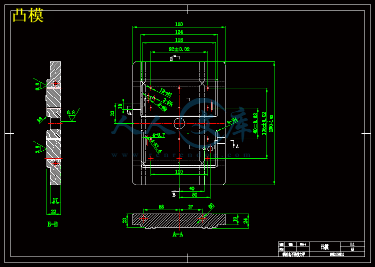
凸模.exb
动模座板.exb
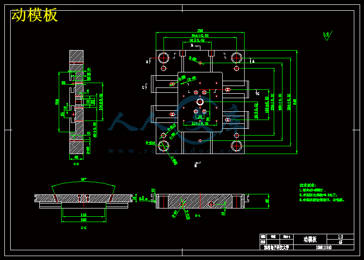
动模板.exb
定模座板.exb
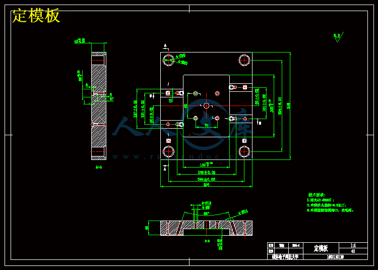
定模板.exb
手机后盖.exb
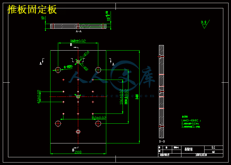
推板固定板.exb
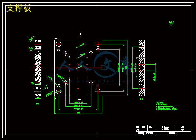
支撑板.exb
装配体.exb
主浇套.dwg
凸模.dwg
动模座板.dwg
动模板.dwg
定模座板.dwg
定模板.dwg
手机后盖.dwg
推板固定板.dwg
支撑板.dwg
装配体.dwg
压缩包内文档预览:
预览图 预览图
编号:10112843    类型:共享资源    大小:7.28MB    格式:RAR    上传时间:2018-05-20 上传人:俊****计 IP属地:江苏
40
积分
关 键 词:
手机 注塑 设计 10 cad 图纸 以及 说明书 仿单
资源描述:

摘  要

我国塑料模具工业从起步到现在,经历了半个世纪,有了很大发展,模具水平有了较大的提高。由于模具生产产品具有精度高,复杂性高,一致性好,生产效率高消耗低等优点。所以现代工业中将会起到更大的作用,得到更多的应用。我的塑料发展至今,已能生产精度高达2微米的精密,多工位级进模,工位数最多已达160个,寿命1~2亿次。

模具时现代工业发展的基础,许多产业的发展都离不开模具行业的支持。用模具生产制造所表现出来的的高精度,高复杂程度,高一致性,高生产率和低消耗,是其他加工制造方法所不能比拟的。在模具工业的总产值中塑料模具约占33%。不同的塑料成型方法使得模具原理和结构不通。按照成型方法的不通,塑料模具分为:注塑模具,压塑模具,吹塑模具等。注塑模具主要用于热塑性塑料制品的成型中占有很大比重。现代工业中,消费品外壳的色彩,手感,和精度,厚度等提出了新要求。塑料外壳设计成为重要的一环。设计合理的注塑模具将得到越来越多的应用。

现代注塑模具的设计方法目前为了应付当前多样化的要求,缩短产品只在周期以缺德最佳的竞争优势,模具设计中都引用了CAD/CAE计算机一体化制造技术,以提高产品质量,降低成本,增加竞争力,一般而言,一件完整理想的工业产品,其制造流程为现有原创型的概念设计出原件,配合计算机辅助工程分析技术,再依据分析结果修改测试,最后再依据设计图经由计算机辅助制造,进行产品自动化生产在模具设计生产,以上整个过程均在计算机上进行。

在模具设计生产过程中,应用Pro/ENGINEER软件进行模具结构设计-模具型腔-型芯二维设计-工艺准备-模具型腔,型芯设计三维造型等。

随着计算机技术和网络技术取得了突破性的成就,模具设计越来越多地使用CAD/CAM技术。在产品生产之前,使用这些新技术来进行模具的设计和改善,是现代设计必然趋势在现实生活里,手机已经成为人们的一个生活必须品,现代的手机已经不再仅仅是一个工具同时一时装饰品,所以做出的不管是手机机身还是手机壳都需要美观大方,因此加工工艺就显得非常重要。所以在对手机壳的模具设计时不仅要考虑成型,还需要考虑成型后的美观。因此在模具的设计过程中多方兼顾。

关键字:手机;模具设计;注射模;斜导柱;侧抽芯。


Abstract

Plastic mold industry in China from the beginning to now, has experienced half a century, has made great development, mould level has greatly improved. Because the mold production product has high accuracy, high complexity, good consistency and high efficiency low consumption etc. So modern industry will play a greater role, get more applications. Precision plastic development up to now, I have been able to produce as much as 2 micron precision, multi-station progressive die, has reached the maximum number of stations in 160, life 1 ~ 200 million times.

Mould the basis for the development of modern industry, many industry's development cannot leave the mould industry support. With mold manufacturing of high precision, high complexity, high consistency, high productivity and low consumption, is can't be matched by other methods of processing and manufacturing. In the mold industry plastic mould accounted for about 33% of the total output. Different methods of plastic molding makes mold principle and structure. According to the forming method of impassability, plastic mold is divided into: injection mold, compression mold, blow molding mould, etc. In the injection mold is mainly used for thermoplastic plastics molding occupies a large proportion. In modern manufacturing, consumer goods shell color, feel, and precision, thickness, etc. Put forward new requirements. Plastic shell design become important one annulus. Reasonable design of injection mould will be applied more and more.

Modern design method of injection mould at present in order to cope with the current diversified requirements, shorten the product by the wicked the best competitive advantage, only in the cycle of mould design reference the CAD/CAE technology of computer integrated manufacturing, in order to improve the product quality, reduce cost, increase the competitiveness, in general, a complete ideal industrial products, the concept of the manufacturing process for existing original type original design, with computer aided engineering analysis techniques, according to the results of analysis, modifying test again, and then on the basis of design through computer aided manufacturing, automated production in the mold design production, more than the whole process are conducted on the computer.

In the mold design and production process, the application of Pro/ENGINEER software to design the mould structure - the mold - core of two-dimensional design process to prepare - mold cavity, core design three dimensional modeling, etc.

Along with the computer technology and network technology has achieved breakthrough and mold design are increasingly using CAD/CAM technology. Before production, the use of these new technologies for the design of the mould and improvement, is an inevitable trend in the modern design in real life, mobile phones have become a people living necessities, modern mobile phone is no longer just a tool for decoration at the same time, so the mobile body or following needs to be beautiful and easy, so the processing technology is very important. So when opponents casing mold design should not only consider the forming, also need to consider after molding. Therefore, in the mold design process to two or morethings.

Key words:Cell phones, mold design, injection mould, inclined guide pillar, side core-pulling


目录

引言 1

第一章  塑件分析 2

1.1 材料的分析 2

1.2 塑件相关参数的设计 2

    1.2.1 注射温度的影响 2

1.3 塑件原料的分析 3

    1.3.1 PC塑料的干燥 3

    1.3.2注射温度 3

    1.3.3注射压力 3

    1.3.4注射速度 3

    1.3.5模具温度 4

1.4 体积及质量计算 4

    1.4.1 体积的计算 4

    1.4.2 质量及面积的计算 4

第二章  型腔数目的确定 6

第三章  成型零部件的设计 7

3.1 型腔尺寸的计算 7

3.2 型芯尺寸的计算 7

第四章  注射机的选择 9

第五章  注射机的校核 10

5.1注射机注射容量校核 10

5.2注射机锁模力校核 10

5.3注射机注射压力校核 10

5.4注射机模具厚度校核 11

5.5注射机最大开模行程校核 11

第六章  分型面的选择 13

6.1 分形面的形式 13

6.2 分型面的选择 13

第七章  浇注系统的设计 15

7.1 分流道的设计原则 15

7.2 分流道的设计 16

7.3 分流道的尺寸的设计 17

第八章  浇口的设计 18

8.1浇口位置选择的仿真 19

8.2 直接浇口的直径设计 19

8.3 点浇口直径设计 20

第九章  冷却系统的设计 21

9.1 冷却系统设计原则 21

9.2 冷却系统的结构形式 21

9.3 冷却系统的计算 21

9.4冷却时间计算 22

9.5 用水量M的计算 23

9.6  成型周期计算 23

第十章  模具材料选择 25

第十一章  模具主要参数的计算 26

11.1 脱模力的计算 26

11.2 初始脱模力 26

11.3 推杆直径计算 27

11.4 推杆的应力校核 27

11.5 推板的厚度计算 28

第十二章  推出脱模机构设计 29

12.1 推出机构的选用原则 29

12.2 推杆的形式 29

12.3 推杆材料 30

12.4 推杆的复位 30

12.5 推出力的计算 30

12.6 型腔壁厚和底板厚度计算 31

    12.6.1侧壁厚度计算 32

    12.6.2矩形型腔底板厚度计算 32

第十三章  结构零部件设计 33

13.1 合模导向机构的设计 33

    13.1.1设计导柱需要注意的事项 33

13.2 导向机构的设计 33

13.3 定位圈的设计 34

13.4 侧向分型与抽芯机构的设计 34

13.5 斜导柱的设计 36

13.6 滑块的设计 37

13.7 楔紧块的设计 37

第十四章  模架的选择 38

14.1模架厚度H和注射机的闭合距离L 38

14.2所需行程之间的尺寸关系 38

第十五章  排气系统的设计 40

第十六章  成型零件加工工艺规程 41

谢辞 42

参考文献 43

附录 44


引言

    随着我国制造业的迅速发展,一些新兴产业业取得了长足的进步。模具是工业生产的基础工艺装备,在机械、电子、汽车、航空以及通信等领域有着广泛的应用。随着人民生活水平的不断提高,日常生活中使用的物品越来越多地用到了模具。目前,模具生产水平的高低已经成为衡量一个国家制造水平高低的重要标志。

当前,计算机技术和网络技术取得了突破性的成就,CAD/CAM技术、数控加工技术以及快速成型技术为模具技术的发展提供了强大的技术支持。同时,以高分子塑料为主的模具材料不断被开放出来,这些材料种类繁多,性能优良,价格低廉,这更为模具产业的发展提供了有力的帮助。

本设计主要是为让读者们能够清楚地了解到塑料注射模的设计过程,能够对模具设计过程中所使用的各种基本工具,例如Pro/ENGINEER,Moldflow Plastics Insight等等,具有一个基本的了解。从零件的尺寸确定,模具设计,模架设计,到最后的注塑仿真,向读者们展示手机塑料模具的整个设计过程。

随着Pro/ENGINEER的不断完善,借助于Pro/ENGINEER设计软件,我们可以比较轻松地完成一些复杂的设计工作,同时也可以全面地提高设计效率和设计质量。


内容简介:
编号: 毕业设计( 论文)说明书题 目: 手机后盖注塑模设计 院 (系): 专 业:学生姓名: 学 号: 指导教师单位: 姓 名: 职 称: 题目类型: 理论研究 实验研究 工程设计 工程技术研究 软件开发2014 年 04 月 27 日摘 要我国塑料模具工业从起步到现在,经历了半个世纪,有了很大发展,模具水平有了较大的提高。由于模具生产产品具有精度高,复杂性高,一致性好,生产效率高消耗低等优点。所以现代工业中将会起到更大的作用,得到更多的应用。我的塑料发展至今,已能生产精度高达 2 微米的精密,多工位级进模,工位数最多已达 160 个,寿命 12 亿次。模具时现代工业发展的基础,许多产业的发展都离不开模具行业的支持。用模具生产制造所表现出来的的高精度,高复杂程度,高一致性,高生产率和低消耗,是其他加工制造方法所不能比拟的。在模具工业的总产值中塑料模具约占 33%。不同的塑料成型方法使得模具原理和结构不通。按照成型方法的不通,塑料模具分为:注塑模具,压塑模具,吹塑模具等。注塑模具主要用于热塑性塑料制品的成型中占有很大比重。现代工业中,消费品外壳的色彩,手感,和精度,厚度等提出了新要求。塑料外壳设计成为重要的一环。设计合理的注塑模具将得到越来越多的应用。现代注塑模具的设计方法目前为了应付当前多样化的要求,缩短产品只在周期以缺德最佳的竞争优势,模具设计中都引用了 CAD/CAE 计算机一体化制造技术,以提高产品质量,降低成本,增加竞争力,一般而言,一件完整理想的工业产品,其制造流程为现有原创型的概念设计出原件,配合计算机辅助工程分析技术,再依据分析结果修改测试,最后再依据设计图经由计算机辅助制造,进行产品自动化生产在模具设计生产,以上整个过程均在计算机上进行。在模具设计生产过程中,应用 Pro/ENGINEER 软件进行模具结构设计-模具型腔- 型芯二维设计- 工艺准备 -模具型腔,型芯设计三维造型等。随着计算机技术和网络技术取得了突破性的成就,模具设计越来越多地使用 CAD/CAM 技术。在产品生产之前,使用这些新技术来进行模具的设计和改善,是现代设计必然趋势在现实生活里,手机已经成为人们的一个生活必须品,现代的手机已经不再仅仅是一个工具同时一时装饰品,所以做出的不管是手机机身还是手机壳都需要美观大方,因此加工工艺就显得非常重要。所以在对手机壳的模具设计时不仅要考虑成型,还需要考虑成型后的美观。因此在模具的设计过程中多方兼顾。关键字:手机;模具设计;注射模;斜导柱;侧抽芯。AbstractPlastic mold industry in China from the beginning to now, has experienced half a century, has made great development, mould level has greatly improved. Because the mold production product has high accuracy, high complexity, good consistency and high efficiency low consumption etc. So modern industry will play a greater role, get more applications. Precision plastic development up to now, I have been able to produce as much as 2 micron precision, multi-station progressive die, has reached the maximum number of stations in 160, life 1 200 million times.Mould the basis for the development of modern industry, many industrys development cannot leave the mould industry support. With mold manufacturing of high precision, high complexity, high consistency, high productivity and low consumption, is cant be matched by other methods of processing and manufacturing. In the mold industry plastic mould accounted for about 33% of the total output. Different methods of plastic molding makes mold principle and structure. According to the forming method of impassability, plastic mold is divided into: injection mold, compression mold, blow molding mould, etc. In the injection mold is mainly used for thermoplastic plastics molding occupies a large proportion. In modern manufacturing, consumer goods shell color, feel, and precision, thickness, etc. Put forward new requirements. Plastic shell design become important one annulus. Reasonable design of injection mould will be applied more and more.Modern design method of injection mould at present in order to cope with the current diversified requirements, shorten the product by the wicked the best competitive advantage, only in the cycle of mould design reference the CAD/CAE technology of computer integrated manufacturing, in order to improve the product quality, reduce cost, increase the competitiveness, in general, a complete ideal industrial products, the concept of the manufacturing process for existing original type original design, with computer aided engineering analysis techniques, according to the results of analysis, modifying test again, and then on the basis of design through computer aided manufacturing, automated production in the mold design production, more than the whole process are conducted on the computer.In the mold design and production process, the application of Pro/ENGINEER software to design the mould structure - the mold - core of two-dimensional design process to prepare - mold cavity, core design three dimensional modeling, etc.Along with the computer technology and network technology has achieved breakthrough and mold design are increasingly using CAD/CAM technology. Before production, the use of these new technologies for the design of the mould and improvement, is an inevitable trend in the modern design in real life, mobile phones have become a people living necessities, modern mobile phone is no longer just a tool for decoration at the same time, so the mobile body or following needs to be beautiful and easy, so the processing technology is very important. So when opponents casing mold design should not only consider the forming, also need to consider after molding. Therefore, in the mold design process to two or morethings.Key words:Cell phones, mold design, injection mould, inclined guide pillar, side core-pulling目录引言 .1第一章 塑件分析 .21.1 材料的分析 .21.2 塑件相关参数的设计 .21.2.1 注射温度的影响 .21.3 塑件原料的分析 .31.3.1 PC 塑料的干燥 .31.3.2 注射温度 .31.3.3 注射压力 .31.3.4 注射速度 .31.3.5 模具温度 .41.4 体积及质量计算 .41.4.1 体积的计算 .41.4.2 质量及面积的计算 .4第二章 型腔数目的确定 .6第三章 成型零部件的设计 .73.1 型腔尺寸的计算 .73.2 型芯尺寸的计算 .7第四章 注射机的选择 .9第五章 注射机的校核 .105.1 注射机注射容量校核 .105.2 注射机锁模力校核 .105.3 注射机注射压力校核 .105.4 注射机模具厚度校核 .115.5 注射机最大开模行程校核 .11第六章 分型面的选择 .136.1 分形面的形式 .136.2 分型面的选择 .13第七章 浇注系统的设计 .157.1 分流道的设计原则 .157.2 分流道的设计 .167.3 分流道的尺寸的设计 .17第八章 浇口的设计 .188.1 浇口位置选择的仿真 .198.2 直接浇口的直径设计 .198.3 点浇口直径设计 .20第九章 冷却系统的设计 .219.1 冷却系统设计原则 .219.2 冷却系统的结构形式 .219.3 冷却系统的计算 .219.4 冷却时间计算 .229.5 用水量 M 的计算 .239.6 成型周期计算 .23第十章 模具材料选择 .25第十一章 模具主要参数的计算 .2611.1 脱模力的计算 .2611.2 初始脱模力 .2611.3 推杆直径计算 .2711.4 推杆的应力校核 .2711.5 推板的厚度计算 .28第十二章 推出脱模机构设计 .2912.1 推出机构的选用原则 .2912.2 推杆的形式 .2912.3 推杆材料 .3012.4 推杆的复位 .3012.5 推出力的计算 .3012.6 型腔壁厚和底板厚度计算 .3112.6.1 侧壁厚度计算 .3212.6.2 矩形型腔底板厚度计算 .32第十三章 结构零部件设计 .3313.1 合模导向机构的设计 .3313.1.1 设计导柱需要注意的事项 .3313.2 导向机构的设计 .3313.3 定位圈的设计 .3413.4 侧向分型与抽芯机构的设计 .3413.5 斜导柱的设计 .3613.6 滑块的设计 .3713.7 楔紧块的设计 .37第十四章 模架的选择 .3814.1 模架厚度 H 和注射机的闭合距离 L.3814.2 所需行程之间的尺寸关系 .38第十五章 排气系统的设计 .40第十六章 成型零件加工工艺规程 .41谢辞 .42参考文献 .43附录 .44桂林电子科技大学毕业设计(论文)说明书 第 0 页 共 44 页引言随着我国制造业的迅速发展,一些新兴产业业取得了长足的进步。模具是工业生产的基础工艺装备,在机械、电子、汽车、航空以及通信等领域有着广泛的应用。随着人民生活水平的不断提高,日常生活中使用的物品越来越多地用到了模具。目前,模具生产水平的高低已经成为衡量一个国家制造水平高低的重要标志。当前,计算机技术和网络技术取得了突破性的成就,CAD/CAM 技术、数控加工技术以及快速成型技术为模具技术的发展提供了强大的技术支持。同时,以高分子塑料为主的模具材料不断被开放出来,这些材料种类繁多,性能优良,价格低廉,这更为模具产业的发展提供了有力的帮助。本设计主要是为让读者们能够清楚地了解到塑料注射模的设计过程,能够对模具设计过程中所使用的各种基本工具,例如 Pro/ENGINEER,Moldflow Plastics Insight 等等,具有一个基本的了解。从零件的尺寸确定,模具设计,模架设计,到最后的注塑仿真,向读者们展示手机塑料模具的整个设计过程。随着 Pro/ENGINEER 的不断完善,借助于 Pro/ENGINEER 设计软件,我们可以比较轻松地完成一些复杂的设计工作,同时也可以全面地提高设计效率和设计质量。使用 EMX 注塑模具设计专家系统可以轻松完成模具模架及配件的设计工作,并能模拟开模过程。EMX 具有完整的滑块结构和完整的开模机构,为设计者带来极大的方便。设计完成后可以直接输出 3D 化模型。Moldflow Plastics Insight 是一款应用广泛的模拟仿真软件,使用该软件可以全面模拟注塑成型过程,并以图形的方式直观地显示分析结果,为设计参数的确定和优化提供理论依据,可以帮助设计者进一步修改模具设计方案。桂林电子科技大学毕业设计(论文)说明书 第 1 页 共 44 页第一章 塑件分析1.1 材料的分析通常,选择塑件的材料依据是它所处在的工作环境及使用性能的要求,以及原材料厂家提供的材料性能数据。对于常温工作状态下的结构件来说,要考虑的主要是材料的力学性能,如屈服应力,弹性模量,弯曲强度,表面硬度等。综合各项因素最后选择 PC 塑料作为本次设计所使用的材料最为适合。PC 塑料的工艺特点如下:(1)属无定型塑料,Tg 为 149150;Tf 为 215225;成型温度为250310;相对平均分子质量为 24 万。 (2)热稳定性较好,并随相对分子质量的增大而提高。 (3)流变特性接近牛顿液体,表观粘度受温度的影响较大,受剪切速率的影响较小,随相对平均分子质量的增大而增大。无明显的熔点,熔体粘度较高。PC 分子链中有苯环,所以,分子链的刚性大。 (4)PC 的抗蠕变性好,尺寸稳定性好;但内应力不易消除。 (5)PC 高温下遇水易降解,成型时要求水分含量在 0.02以下。 (6)制品易开裂。在成型前,PC 树脂必须进行充分干燥。干燥方法可采用沸腾床干燥(温度 120130 ,时间 12h) 、真空干燥(温度 110,真空度96kPa 以上、时间 1025h)、热风循环干燥(温度 120130,时间 6h 以上)。为防止干燥后的树脂重新吸湿,应将其置于 90的保温箱内,随用随取,不宜久存。成型时料斗必须是密闭的,料斗中应设有加热装置,温度不低于 100、对无保温装置的料斗,一次加料量最好少于半小时的用量,并要加盖盖严。1.2 塑件相关参数的设计1.2.1 注射温度的影响PC 塑料的大分子多呈无定形状态,大约 215开始软化,225以上开始流动。和其它热塑性塑料相比,PC 塑料不仅熔融温度高,而且熔融后的熔体粘度也较高,熔体粘度对温度的敏感性比剪切速率大。一般对于低于 260的料温,由于其熔体粘度过高,制品易出现不足,波纹等缺陷,故在成型中较少采用,而大都选用 270320之间,在此范围内的熔体粘度适中,适合于大部份制品的成型。PC 塑料在正常加工温度范围内有很好 的热稳定性,在 300温度下长时间停留于料筒内基本不分解 ,熔体粘度变化也很小,由于这一特性使其在成型过程中可以多次反复使用。桂林电子科技大学毕业设计(论文)说明书 第 2 页 共 44 页注射温度对 PC 塑料产品的性能有着重要的影响,在 280300之间,PC 塑料成型前后的分子量变化较小,实验证明,除了伸长率有所下降外,冲击强度,拉伸强度和弯曲强度等项性能指标均有较高的值,同时产品有良好的外观和光亮的表面。过高的料温,如超过 340时,PC 塑料将会出现分解,产品颜色变深,表面出现银丝、暗条、黑点、气泡等缺陷,同时物理机械性能也显著下降。另外,含氮化合物的存在也会使分解加速,需予以注意。1.3 塑件原料的分析1.3.1 PC 塑料的干燥 该种材质对微量的水分极为敏感, 极易吸咐水分,使成型塑件表面出现斑痕、云纹等缺陷。为了使注塑制品达到最佳效果,减少降解的可能性,PC/ABS在成型加工前必须进行干燥,使材料含水量降至0.04%以下,最好在0.02%以下,以提高加工稳定性和机械性能。一般地用电热鼓风烘箱在90110 ,预干燥46小时,可以达到所需要的含水率。但最长累积干燥时间不能超过48小时,否则材料有降解变色的可能。1.3.2 注射温度PC成型温度低较, 加工成型性好 ,热变形温度在115 左右, 采用合适的加工温度, 可以减少或消除表面凹痕, 同时也可以减少缩孔。成型温度设定以确保阻燃PC 充分塑化为基准,应尽量使用低温区域,以防止材料降解。成型温度增加会明显地降低阻燃PC/ABS的粘度,增加树脂的流动性,因而,使流动距离变长。原则上,当使用建议的成型温度上限时,应使熔胶滞留时间尽可能短,避免降解的产生。因此PC成型温度一般为 230270。1.3.3 注射压力PC 在注射时采用中等的注射压力,一般为 80150MPa。 对小型、构造简单、厚度大的制件可以用较低的注射压力。PC 树脂的表现黏度强烈地依赖于剪切速率,因此模具设计中大都采用点浇口形式。1.3.4 注射速度较快的注塑速度,一般会使流程加长,适合充填薄壁制品,并形成较好的表面光洁度,但过快的注塑速度会产生强剪切导致材料降解。而慢速注塑速度可以帮助避免浇口白晕、喷射痕和流痕等缺陷。此手机保护壳为薄壁制品,宜采用中等注射速度,将摩擦热降至最小;采用多级注射,以确保充填顺畅和制品外观。 桂林电子科技大学毕业设计(论文)说明书 第 3 页 共 44 页1.3.5 模具温度 模具温度模具温度控制对决定最终制件的充填程度、外观、残余应力是非常重要的。PC 的成型温度相对较高 , 模具温度也相对较高。一般调节模温为模具温度:50100 。较高的模具温度,往往会产生良好的流动、较高的熔接线强度、较小的产品内应力,但成型周期会延长。若模具温度比建议的低,就会导致高内应力并损坏制件的最佳性能。就制件表面和循环周期而言,模具温度为建议温度范围的中间值时,可望得到较好的结果。1.4 体积及质量计算1.4.1 体积的计算对笔套面积进行计算,如图 1.1 所示:图 1.1 手机后盖图纸已知: =125.5mm =123.5mm =7mm =6mm =62.5mm 1L2L1H21D=60.5mm2D=8.5/2mm =4/2mm =3.75/2mm =0.71mm =5.32mm =1.42mm 1R23R43L4L体积为:(1-1) 2/1)( 4432321211 RRDHLV 从而总体体积为:V=9344.07 m查表塑料模设计手册之二表 1.4 可知 abs 塑料的密度为 =1.20g/cm1.4.2 质量及面积的计算(1)单个塑件质量:毕业设计(论文)中期检查表(指导教师)指导教师姓名: 填表日期: 学生学号 学生姓名 题目名称 手机保护壳注塑模设计已完成内容开题并做调研,进行翻译;确定其方案设计;完成结构设计;绘制结构草图;完成相关计算;完成英文翻译;绘制装配图;绘制零件图;撰写论文;完成毕业设计。检查日期:2014-4-20完成情况 全部完成按进度完成滞后进度安排存在困难解决办法查阅相关资料,并且与指导老师和同学们一起讨论解决方案。预期成绩 优 秀 良 好 中 等 及 格 不及格建议教师签名:教务处实践教学科制表说明:1、本表由检查毕业设计的指导教师如实填写;2、此表要放入毕业设计(论文)档案袋中;3、各院(系)分类汇总后报教务处实践教学科备案编号: 毕业设计( 论文)任务书题 目: 手机后盖注塑模设计 学 院: 专 业: 学生姓名: 学 号: 指导教师单位: 姓 名: 职 称: 题 目 类 型 : 理 论 研 究 实 验 研 究 工 程 设 计 工 程 技 术 研 究 软 件 开 发2013 年 12 月 9 日一、 毕业设计(论文)的内容1、塑件的分析 2、塑件材料的选用与性能分析(特性及成型工艺参数)3、拟定模具的结构形式(型腔的数目及排布) 4、浇注系统的设计 5、分流道的设计 6、浇口的设计 7、冷料穴和拉料杆的设计 8、成型零件的设计 9、导向机构的设计10、脱模推出机构的设计 11、侧向分型与抽心机构设计 12、排气系统的设计 13、温度调节系统的设计 14、限位钉设计二、毕业设计(论文)的要求与数据1、外型尺寸及配合精度必须标注2、使用环境-10403、电气性能符 GB 标准4、外观要求美观坚固5、根据实际情况确定脱模斜度 6、ABS 主要技术指标及工艺参数 7、设计中的计算 8、安装尺寸的校核三、毕业设计(论文)应完成的工作1、完成二万字左右的毕业设计说明书(论文) ;在毕业设计说明书(论文)中必须包括详细的 300-500 个单词的英文摘要;2、独立完成与课题相关,不少于四万字符的指定英文资料翻译(附英文原文) ;3、对于纯机械类课题,绘图工作量折合 A0 图纸 3 张以上,其中必须包含两张 A3 以上的计算机绘图图纸;四、应收集的资料及主要参考文献1 李学峰.塑料模设计及制造M.北京:机械工业出版社.20012 翁其金.塑料模塑成型技术. M.北京:机械工业出版社.20023 钱泉森.塑料成型工艺及模具设计. M.济南:山东科学技术出版社,20044 塑料模设计手册编著组.塑料设计手册.北京:机械工业出版社.20025 陈剑鹤.模具设计基础. M.北京:机械工业出版社,20046 王文广等.塑料注塑模具设计技巧与实例M.北京:化学工业出版社,20047 章飞.型腔模具设计与制造.M.北京:化学工业出版社,20038 谭雪松,林晓新,温利编.新编塑料模设计手册.北京:人民邮电出版社,2007.19 朱光.塑料注塑模中小型模架及其技术条件M.北京:清华大学出版社,2003,110 cunha,L,et.al.,performance of chromium nitride and titanium nitride coatings during platics injection moulding. Surface and coating Technology, 2002.153(2-3):p.160-165.五、试验、测试、试制加工所需主要仪器设备及条件计算机(autoCAD, 及 pro/E,protel 软件)任务下达时间:2013 年 12 月 4 日毕业设计开始与完成时间:2013 年 12 月 7 日至 2014 年 05 月 26 日组织实施单位:教研室主任意见:签字: 2013 年 12 月 10 日院领导小组意见:签字: 2013 年 12 月 12 日编号: 毕业设计(论文)开题报告题 目: 手机后盖注塑模设计 院 (系): 专 业: 学生姓名: 学 号: 指导教师单位: 姓 名: 职 称: 题 目 类 型 : 理 论 研 究 实 验 研 究 工 程 设 计 工 程 技 术 研 究 软 件 开 发2013 年 12 月 23 日开题报告填写要求1开题报告作为毕业设计(论文)答辩委员会对学生答辩资格审查的依据材料之一。此报告应在指导教师指导下,由学生在毕业设计(论文)工作前期内完成,经指导教师签署意见审查后生效。 2开题报告内容必须用黑墨水笔工整书写,或按教务处统一设计的电子文档标准格式打印,禁止打印在其它纸上后剪贴,完成后应及时交给指导教师签署意见。3学生查阅资料的参考文献应在 5 篇及以上(不包括辞典、手册) 。4有关年月日等日期的填写,应当按照国标 GB/T 740894数据元和交换格式、信息交换、日期和时间表示法规定的要求,一律用阿拉伯数字书写。如“2004 年 4 月 26 日”或“2004-04-26” 。1. 本课题的研究内容、重点及难点本次研究设计了塑料手机保护壳的材料特点以及相关内容,主要描述该手机保护壳的成型加工工艺,包括注射模结构,各大系统和机构的设计,以及各零部件参数的校核。此次设计中有许多地方需要仔细研究,其重点难点如下:1、脱模推出机构和侧抽芯机构的设计;2、塑件的合理性设计及结构工艺性分析;3、材料选择,收缩率计算。模具强度及刚度分析;4、塑件壁厚成型工艺考虑及保证塑件的外观要求;5、模具型腔数的确定,模具结构、分型面和进料口形式的选择;6、保证塑件成型时无变形,注出的制件表面光滑,无气泡和其它缺陷,无飞边或少飞边;7、绘制模具总装图、零件图及尺寸标注。2. 准备情况(查阅过的文献资料及调研情况、现有设备、实验条件等)随着我国制造业的迅速发展,一些新兴产业业取得了长足的进步。模具是工业生产的基础工艺装备,在机械、电子、汽车、航空以及通信等领域有着广泛的应用。随着人民生活水平的不断提高,日常生活中使用的物品越来越多地用到了模具,特别是现代社会,人们对于手机的需求越来越高,手机已经从生活的调味品变成了必需品,手机后盖的生产主要以注塑模具生产,注塑模生产具有生产效率高,成本低等特点,非常适合手机后盖的生产。当前,计算机技术和网络技术取得了突破性的成就,CAD/CAM 技术、数控加工技术以及快速成型技术为模具技术的发展提供了强大的技术支持。同时,以高分子塑料为主的模具材料不断被开放出来。这些材料种类繁多,性能优良,价格低廉,这更为模具产业的发展提供了有力的帮助。本设计主要是为了够清楚地阐述塑料注射模的设计过程,能够对模具设计过程中所使用的各种基本工具,例如UG/Pro/ENGINEER,Moldflow Plastics Insight 等等,具有一个基本的了解。本次主要是对手机的后盖进行设计,从零件的尺寸确定,到模具设计、模架设计,全面阐述了手机后盖注塑模具的整个设计过程。到目前,已经做了十足的准备,认真阅读了解了许多相关资料,其中包括1 郭新玲编著.塑料模具设计M.北京:清华大学出版社,2006.2 2006 HERBERT W.YANKEE MANUFACTURING PROCESSES Prentice-Hall, Inc.3 张信群.塑料成型工艺与模具结构M.北京:人民邮电出版社,20084 窦召领.模具机械加工技术M.武汉:科技大学出版社,20085 张信群.模具制造技术M.北京:人民邮政出版社,20096 谢琴香.模具设计及计算机应用M.华南理工出版社,20087 程志远.实用注塑模设计手册M.中国轻工业出版社8 杨叔子.机械加工工艺师手册M.北京:机械工业出版社9 机械设计手册M.北京:机械工业出版社10 黄义俊.模具 CAD/CAM 技术M.北京:人民邮电出版社,2009.11 李小敏.计算机辅助设计-CAD/CAE/CAPP/CAMM.北京:清华大学出版社.2008.412 颜智伟编著.塑料模具设计与机构设计M.北京: 国防工业出版社.2006.13 张中元.塑料成型工艺与模具设计M. 北京:航空工业出版社,2006.14 陈剑鹤.模具设计基础M.北京:机械工业出版社,2003.15 李云程.模具制造工艺学M.机械工业出版社,20053. 实施方案、进度实施计划及预期提交的毕业设计资料2013 年 12 月 17 日至 2013 年 12 月 30 日,阅读执行毕设任务书要求并收集整理资料文献,根据毕设内容完成并交开题报告;2013 年 1 月 6 日至 2014 年 1 月 13 日,开展调研,了解塑件结构,对原材料进行分析,考虑塑件的成型工艺性、模具的总体结构的形式,并完成部分英文摘要翻译;2014 年 3 月 4 日至 2013 年 3 月 31 日,查阅资料,熟悉注射模的结构及有关计算,拟定模具的方案设计、总体设计及主要零件设计,拟定成型工艺过程,查阅有关手册确定适宜的工艺参数,注射机的选择及确定注射设备及型号规格;2014 年 4 月 1 日至 2014 年 4 月 21 日,完成设计计算任务,总体结构的设计和完成总装配图及零件图的设计;2014 年 4 月 22 日至 2014 年 5 月 5 日,完成设计,图纸绘制任务,工艺规程说明书的编写;2014 年 5 月 6 日至 2014 年 5 月 20 日,完善设计并完成论文的撰写;2014 年 5 月 20 日至 2014 年 5 月 26 日,修改并打印毕业论文及整理相关资料,交指导老师评阅,准备论文答辩。指导教师意见指导教师:年 月 日开题小组意见开题小组成员签字: 年 月 日院系审核意见院系主管领导签字:年 月 日 编号: 毕业设计(论文)外文翻译(原文)学 院: 国防生学院 专 业:学生姓名: 学 号: 指导教师单位: 姓 名: 职 称: 2014 年 3 月 9 日contentsRapid Prototyping Versus Virtual Prototyping in Product Design and Manufacturing 1prolonging lifetime ofservice life of die based on deform 13第 0 页 共 29 页Rapid Prototyping Versus Virtual Prototyping in Product Design and ManufacturingC. K. Chua1, S. H. Teh1 and R. K. L. Gay2School of Mechanical and 2Gintic Institute of Manufacturing Technology, Nanyang Technological University, SingaporeAbstractRapid prototyping (RP) is the production of a physical model from a computer model without the need for any jig or fixture or numerically controlled (NC) programming. This technology has also been referred to as layer manufacturing, material deposit manufacturing, material addition manufacturing, solid freeform manufacturing and three-dimensional printing. In the last decade, a number of RP techniques has been developed. These techniques use different approaches or materials in producing prototypes and they give varying shrinkage, surface finish and accuracy. Virtual prototyping (VP) is the analysis and simulation carried out on a fully developed computer model, therefore performing the same tests as those on the physical prototypes. It is also sometimes referred to as computer-aided engineering (CAE) or engineering analysis simulation. This paper describes a comparative study of the two prototyping technologies with respect to their relevance in product design and manufacture. The study investigates the suitability and effectiveness of both technologies in the various aspects of prototyping, which is part and parcel of an overall design and manufacturing cycle.Keywords: Product design; Rapid prototyping; Virtual prototyping第 1 页 共 29 页1. IntroductionRapid prototyping (RP) is emerging as a key prototyping technology with its ability to produce even complicated parts virtually overnight. It enables product designers to shorten the product design and development process. The coming-of-age of this technology is clearly reflected in the inclusion of a stereolithography (STL) file generator in most, if not all, CAD. systems today. The STL file is the de facto standard used by RP systems in the representation of the solid 3D CAD models.While RP is a relatively young technology, virtual prototyping (VP) has been in steady development since the 1970s in many guises. Virtual prototyping is taken to mean the testing and analysis of 3D solid models on computing platforms. Today, VP is often tightly integrated with CAD/CAM software and sometimes referred to as CAE packages. It provides the ability to test part behaviour in a simulated context without the need to manufacture the part first 1.2. Definitions of RP and VPRapid prototyping (RP) is a widely used term in engineering, particularly in the computer software industry where it was first coined to describe rapid software development.This term has also been adopted by the manufacturing industry to characterise the construction of physical prototypes from a solid, powder, or liquid in a short period of time when compared to “traditional” subtractive machining methods. This technology has also been variously referred to as layer manufacturing, material deposit manufacturing, material addition manufacturing, solid freeform manufacturing and threedimensional printing 2.Virtual prototyping (VP) refers to the creation of a model in the computer, often referred to as CAD/CAM/CAE. Virtual or computational prototyping is generally understood to be the construction models of products for the purpose of realistic graphical simulation 1. In this paper, VP will refer to thesimulation, virtual reality and manufacturing process design domains 3.Nevertheless, there are many areas where the distinction between RP and VP is blurred. As RP systems rely on CAD systems to generate the files needed to produce the prototype, it would seem that RP is a downstream process from VP in the product or part development cycle. Indeed, Pratts definition of VP reveals the fact that VP is a term which is loosely used in the prototyping community. As such, it would be 第 2 页 共 29 页appropriate to clearly define both RP and VP.Rapid prototyping will be taken to mean, as above, the production of a physical model from a computer model without the need of any jig or fixture or NC programming. This also includes other related processes and applications which use RP-produced objects, such as rapid tooling.Similarly, VP is defined as the subsequent manipulation of a solid CAD model as a substitute for a physical prototype for the purposes of simulation and analysis, and is not inclusive of the construction of the solid 3D model. VP includes the following functions:1. Finite element analysis.2. Mechanical form, fit and interference checking.3. Mechanical simulation.4. Virtual reality applications.5. Cosmetic modelling.6. Assemblability.The relationships between RP and VP are shown in Fig. 1.Fig. 1. Classification of RP and VP3. Prototyping in SingaporeTwo selected multi-national companies (one American and one French) based in Singapore with significant product development activities showed differing approaches to both RP and VP. Both use RP in their prototyping activities.The first company, B, placed more emphasis on virtual prototyping. It 第 3 页 共 29 页manufactures telecommunications equipment such as pagers and handphones. It is moving all prototyping applications upstream, which is to move prototyping from RP to VP. At present, their RP models are used only for proof of concept and marketing purposes. Other prototyping activities are being carried out with VP.The second company, C, manufactures consumer electronics products such as television sets, video cassette recorders and telephones. It uses VP only as a tool to create a solid 3D model. From the solid 3D model, C generates the STL file needed to produce the RP prototype. Company C then uses the RP part as a master for silicone rubber moulds to produce a limited number of physical ABS (polyacrylonitrite butadienestyrene) prototypes for the various prototyping tests and simulation.Company B intends to move more prototyping to VP, rather than using physical models. Virtual prototyping allows for improvements in reliability and quality as well as reducing costs. Manipulation of virtual prototypes makes it easier for B to implement design improvements compared to an iterative cycle using physical prototypes.Company B drafts the CAD models in Pro/ENGINEER, then uses Patran to pre-process the models. Static finite-element analysis (FEA) is carried out with ABAQUS Standard whereas dynamic scenarios are analysed with ABAQUS Explicit. ALIAS/Wavefront is used for cosmetic modelling when presenting different conceptual and actual designs.The bulk of the VP carried out by B uses FEA, which typically takes 46 weeks for a pager design. Of all the FEA carried out, the majority are concentrated on structural strength (static) analysis and drop test (dynamic) analysis. Vibration tests are occasionally carried out. Some cosmetic modelling is carried out, but usually only for presentation purposes.Finite-element analysis is used to investigate the following problems:Relative comparison of different design options; to see how one design compares to another. Possible failure modes are:1. To evaluate a design change or design correction.2. To assess the possibility of failure, based on past experience.3. To make some educated-guess correlation with physical testing.4. To try to identify what initiated a failure.According to B, the drawback of VP is that it cannot simulate process problems efficiently and effectively. The accuracy of FEA is also limited because of the 第 4 页 共 29 页inconsistent behaviour ofmaterial. The amount of computing power also determines the accuracy of FEA.The application of RP is rather limited in B. The in-house laminated object manufacturing (LOM) RP system is used to produce design prototypes for proof of concept only, and notgeometrical prototypes. Company C uses RP heavily, but has very little VP. The parts produced using RP range from audio products to 29-in. television casings. Typically, it takes 1 year from the conception of the product to the sale of the product. Company C aims to prototype all (mostly plastic) parts by RP. A comparison between numerically controlled (NC) machining of prototypes from ABS against RP is shown in Table 1. Company C projected 50% savings using an in-house RP system versus an NC machining system.CAD models are created using I-DEAS. The .STL format is then created for production of the RP part. The main purpose of the RP parts is to verify the design. Rapid prototyping parts are used for the following functions:1. Form fitting.2. Ergonomics check.3. Proof of concept (to confirm design with industrialdesigners).4. Manufacturability (design for tooling, design for assemblability).5. Reliability check (whether part dislodges or breaks when force applied, especially snap-on covers).6. Kinematic check.Company C offers some insight into the limitations of VP, in that VP is unable to model:1. Tactile feeling (for buttons) not quantified; may be able to VP if able to quantify “pressing” force.2. Assemblability (e.g. PCBs inserted at an angle, difficult to visualise).4. Case Study 1: Prototyping of a Telephone HandsetThis case study investigates the design verification, assembly, interference check and form fitting aspects of both the RP and VP model. The production ABS, RP and VP parts or models were evaluated in the above aspects. The RP system used here is the stereolithography apparatus (SLA). Both the ABS and RP parts are shown in Fig. 2. Inspection of the RP parts reveal that:第 5 页 共 29 页1. The surface finish was much poorer than in the ABS part.2. Warpage was clearly evident (see Fig. 3).4.1 Design VerificationAs a true dimensional physical part, the RP model is able to give the designer a sense of size estimation. The judgement of a VP part can be erroneous because parts are often automatically sized to fit the viewing window. Another advantage of a physical part is that it allows for ergonomic checks, ranging from the fit of a telecommunications device in a users palm to the inspection of potentially dangerous corners and edges. Also, it offers tactile inspection which is crucial in products for which ergonomics is important, such as touch buttons on audio or video products, which is not possible on VP systems.Rounded edges which appear innocuous on a VP model may prove to be unsafe upon scrutiny of the RP part. Above all, most RP parts are produced for aesthetic evaluation purposes. Aesthetic evaluation is also possible on VP models. All CAD software allows the model to be viewed in any spatial orientation, along with at least rudimentary rendering capabilities. It is then possible to view the part under the desired simulated lighting conditions with millions of shading and colour combinations. RP parts cannot be coloured, thus surface preparation and painting introduce additional finishing processes. Any visibly apparent design discrepancies could be immediately rectified without having to invest in a physical part. It also allows designers to evaluate the aesthetics of the design and make corrections, if necessary. In the case of most multi-national companies, the design and manufacturing facilities are often a considerable distance apart and in different countries and continents. The ease with which CAD files can be sent and received via electronic means greatly helps the design process, be it iterative or concurrent. With identical or compatible CAD software, the prototyping process can be swift and cheap. Any design change of the virtual prototype can bemade almost instantly available to all parties involved in the design process.4.2 AssemblyAssembly of RP parts must be carried out quickly, as warpage and shrinkage increases with time. Warpage is a function of both part geometry design and shrinkage. All but the bestdesigned parts suffer from varying degrees of warpage and shrinkage. Some RP material such as the SLA inherently shrinks and the part is 第 6 页 共 29 页actually built slightly larger to allow it to shrink to its proper dimensions. With such arrangements, assembly is possible but is often hampered by warpage and/or shrinkage. Some parts can be mated only with the application of some force. Assembly of RP parts allows the user not only to attempt different assembly sequences, but also if a part cannot be positioned in a linear movement, to insert the part, say, at an angle before being set into its proper location. The drawback in assembling RP parts is that for some RP parts such as SLA, the material is weak and brittle, and fails when attached using fasteners or under low to moderate loading (see Figs 4 and 5). CAD software allows for the assembly of parts and subassemblies in the form of 3D solid or surface models. Assembly in the virtual realm is very often used to check for interference and form fitting which will be discussed later. The ability ofCAD software to assemble parts and/or subassemblies allows a product designer to quickly check to see if he or she has designed the part or parts correctly, i.e. whether a boss is tall enough to accept a screw inserted through another part or if two slots are aligned to form a larger slot. The advantage of assembling in a virtual environment is that no physical parts need be produced and thus this reduces cost. The absence of physical parts also means that tooling time is eliminated. The assembly in a virtual environment can be done in a matter of minutes or up to a few days, but is much faster than producing the physical parts and then assembling them. The user can also build or change a part, or modify its attributes when all instances of the part will be changed accordingly. Assembly relationships can be written in engineering parameters, part dimensions and orientation dimensions. The equations are solved variationally to allow for flexibility while working with the assembly. Evaluation of the tolerance specifications of the design to optimise the engineering performance at the lowest possible cost can be carried out. This allows the user to measure the s
温馨提示:
1: 本站所有资源如无特殊说明,都需要本地电脑安装OFFICE2007和PDF阅读器。图纸软件为CAD,CAXA,PROE,UG,SolidWorks等.压缩文件请下载最新的WinRAR软件解压。
2: 本站的文档不包含任何第三方提供的附件图纸等,如果需要附件,请联系上传者。文件的所有权益归上传用户所有。
3.本站RAR压缩包中若带图纸,网页内容里面会有图纸预览,若没有图纸预览就没有图纸。
4. 未经权益所有人同意不得将文件中的内容挪作商业或盈利用途。
5. 人人文库网仅提供信息存储空间,仅对用户上传内容的表现方式做保护处理,对用户上传分享的文档内容本身不做任何修改或编辑,并不能对任何下载内容负责。
6. 下载文件中如有侵权或不适当内容,请与我们联系,我们立即纠正。
7. 本站不保证下载资源的准确性、安全性和完整性, 同时也不承担用户因使用这些下载资源对自己和他人造成任何形式的伤害或损失。
提示  人人文库网所有资源均是用户自行上传分享,仅供网友学习交流,未经上传用户书面授权,请勿作他用。
关于本文
本文标题:手机后盖注塑模设计【10张CAD图纸和说明书】
链接地址:https://www.renrendoc.com/p-10112843.html

官方联系方式

2:不支持迅雷下载,请使用浏览器下载   
3:不支持QQ浏览器下载,请用其他浏览器   
4:下载后的文档和图纸-无水印   
5:文档经过压缩,下载后原文更清晰   
关于我们 - 网站声明 - 网站地图 - 资源地图 - 友情链接 - 网站客服 - 联系我们

网站客服QQ:2881952447     

copyright@ 2020-2025  renrendoc.com 人人文库版权所有   联系电话:400-852-1180

备案号:蜀ICP备2022000484号-2       经营许可证: 川B2-20220663       公网安备川公网安备: 51019002004831号

本站为文档C2C交易模式,即用户上传的文档直接被用户下载,本站只是中间服务平台,本站所有文档下载所得的收益归上传人(含作者)所有。人人文库网仅提供信息存储空间,仅对用户上传内容的表现方式做保护处理,对上载内容本身不做任何修改或编辑。若文档所含内容侵犯了您的版权或隐私,请立即通知人人文库网,我们立即给予删除!