垂直循环立体停车设备的结构设计-立体车库设计(全套含CAD图纸、三维模型)
收藏
资源目录

压缩包内文档预览:(预览前20页/共39页)
编号:10115160
类型:共享资源
大小:21.47MB
格式:ZIP
上传时间:2018-05-21
上传人:机****料
认证信息
个人认证
高**(实名认证)
河南
IP属地:河南
60
积分
- 关 键 词:
-
垂直
循环
立体
停车
泊车
设备
装备
结构设计
立体车库
设计
全套
cad
图纸
- 资源描述:
-




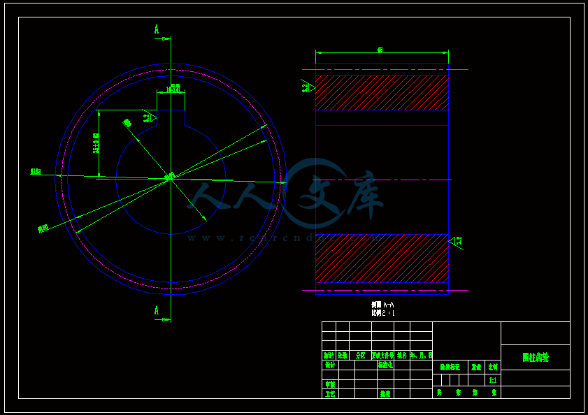

- 内容简介:
-
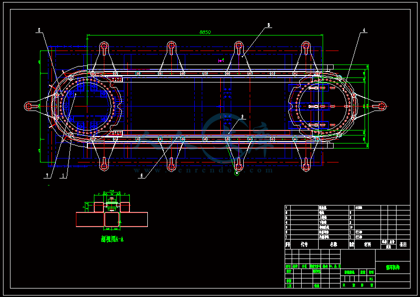
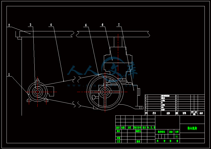
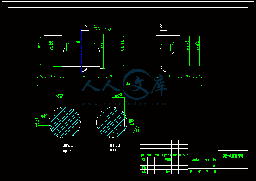
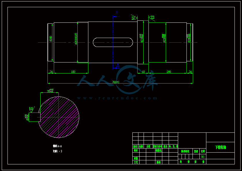
包含 CAD 图纸和三维建模及说明书,咨询 Q 197216396 或 119709851目 录摘 要 .1Abstract .2第 1 章 绪论 .31.1 研究的背景与意义 .31.1.1 研究的背景 .31.1.2 论文研究的意义 .31.2 国内外发展状况 .41.3 立体车库的分类 .51.4 本设计主要研究工作 .8第 2 章 立体车库方案及总体结构设计 .82.1 立体车库总体方案的确定 .82.2 总体结构方案的设计 .92.2.1 机械系统的工作原理 .92.2.2 机械系统的组成 .9第 3 章 升降机构的设计计算 .113.1 驱动系统的设计计算 .113.1.1 电动机的选择 .113.1.2 减速器的选择 .123.1.3 制动器的选择 .123.2 传动系统的设计 .133.2.1 开式齿轮传动设计 .133.2.2 链传动的设计 .163.2.3 轴的设计与校核 .21包含 CAD 图纸和三维建模及说明书,咨询 Q 197216396 或 1197098523.3 结构框架的设计 .253.4 联轴器和键的选择 .283.5 轴承的选择 .303.6 车辆托盘 .30第 4 章换向机构设计 .314.1 换向机构设计 .314.1.1 换向机构总体结构 .314.1.2 转台设计 .324.1.3 蜗轮蜗杆减速器设计 .324.1.4 电机的选择 .344.1.5 带传动设计 .354.1.6 联轴器选择 .36结 论 .36参考文献 .37致谢 .38包含 CAD 图纸和三维建模及说明书,咨询 Q 197216396 或 119709853包含 CAD 图纸和三维建模及说明书,咨询 Q 197216396 或 119709854包含 CAD 图纸和三维建模及说明书,咨询 Q 197216396 或 119709855包含 CAD 图纸和三维建模及说明书,咨询 Q 197216396 或 119709856包含 CAD 图纸和三维建模及说明书,咨询 Q 197216396 或 119709857包含 CAD 图纸和三维建模及说明书,咨询 Q 197216396 或 119709858第 1 章 绪论1.1 研究的背景与意义1.1.1 研究的背景随着改革开放和我国社会、经济的迅速发展,人们生活水平的不断提高,私家车的数量增长十分迅速,使得原本人口就十分密集的城市中,小区、街道的停车位严重的不足停车难的问题日益严重,立体车库无疑是解决小区停车难问题的一种有效途径 1。由于经济和社会的快速发展和城市化档次的提高,车辆的数量飞速的加多。由于过度加多的汽车的数量,因此,城市道路建设的设备无法赶上经济发展的速度,造成严重的交通拥堵和车位的问题。同时停止网站规划不合理、绿地的占领和车道现象,加剧了交通混乱,导致进一步的交通拥堵,摧毁了城市居住环境和交通之间的关系,成就一个恶性循环。目前,中国城市机动车所有权和停车位的比例是 5:1,停车位严重短缺。从城市建设的经验,以确保交通拥堵,不仅要满足基本的停车位 100%,还要满足公共停车位20%。目前,我国大多数城市采用平面式停车场,停车场设备复杂,有效的停车位置很小,面积大,车辆和人员的安全很差。平均下来一辆小汽车占据 40 平方米的面积。因为这些原因,给业主或开发商都是非常不利的。因此,立体车库的建设迫在眉睫,而且我们国家的经济发展,城市的生活水平改善城市静态交通。立体车库以其优势的平面式车库,诞生以来广泛的关注,近年来人们越来越多的关注。本文在这种背景下,试图做一些研究和重建2的停车问题。1.1.2 论文研究的意义为了解决城市停车问题的问题,最小面积,更多的车辆停止,但也允许租户访问车辆安全,方便。垂直循环停车车库,土地利用率高、操作简单、灵活、安全、可靠、适应性强、和许多其他的优点,是主要的大型城市居住区停车问题的方向发展。具体来说,本研究的意义主要在以下方面:1节省空间立体停车库的占地面积为平面停车场的1/2-1/25,空间利用率比建筑自走式停车库提高了75%。尤其在商业中心区、旅游景点、医院、银行、办公楼等人流和车流量大的公共场所,有很大的作用。2垂直循环立体停车库完全采用电脑控制,司机存车更方便该过程自动停车和车辆。老板简单的停车卡或支付到车库,车是非常方便的访问。通常一次保存(采取)车时间为 2 分钟,有效地避免了传统停车库存取车需要走的路程,也节省了找车位的时间,同时也减少了环境的污染,安全便捷 3。3综合投资少垂垂直循环式立体车库占地面积小的空间,空间利用率高。这大大减少了投资的土地面积,操作过程中,低能耗,减少管理,也大大节省了成本。停车场建设具有结构简单、包含 CAD 图纸和三维建模及说明书,咨询 Q 197216396 或 119709859少量的工程投资,只有少量的通风,所以成本大大降低。据统计,每个停车位约 3 - 7 的新停车设备几百万元,15 万元,建设成本 4自航停车位。4配置灵活立体停车库可单独设计,也可依附在其他建筑物内,可设在地上、地下或半地下,型式多样,适应性广。5改善环境新型循环立体停车库不仅可以改变了停车的环境,伴随着也可以降低噪音、污染及土地覆盖,缓解了行车环境,让交通不在如此的拥堵,达到了人、车分流,维护了行人安全的同样也改善了居住生活环境、加强了绿化面积。1.2国内外发展状况1.国内发展状况中国早期研发的机械车库开始于1980年代,河北承德华谊机械车库集团于1989年建立第一个垂直循环机械式停车设备,填补我国空白机械停车场。从90年代开始在北京、上海、广州、深圳等地方开始投入使用。参照国际标准,介绍了中国的行业标准,目前已有上千家公司生产各种类型的停车设备,甚至有些公司的停车设备已开始出口世界各国。机械式立体车库不仅是一个简单的车库、更是一种具有综合性能的建筑,不仅包含了机械停车设备,其规划建设涉及到区域整体景观、建筑结构、通讯监视、环境保护、安全消防、收费管理等各学科领域,就停车设备本身而言,其机械结构的发展已形成了停车设备独有的技术特征,需要全能型的人才把国外更加成熟的技术移植到我国停车产业,开发出更加安全、高效、节能、经济的产品,满足国内外市场不断发展的需求 5。虽然我国的停车设备有了一定的发展,但是依然存在一些问题,例如没有统一的技术标准;大多数的产品都是引进国外技术制造,技术水平较低;而且缺少一定具有规模的企业,生产能力不足;市场竞争混乱,有的企业为抢占市场,选择低价竞争;技术创新能力严重不足和管理严重滞后等。上述问题,需要我们在市场、管理和技术等方面做出努力。确定公共停车位的合理数量,实现投资的多元化,确定车库的管理属性和停车收费标准,对投资者和经营者给予优惠扶持政策。市场方面,建立车库市场运行机制,提高占路停车收费标准,让大家都去选择车库停车。实施政府监督和政策调控,促进产业的良性发展。虽然立体车库发展趋势快,但是目前立体车库的应用却很少。其问题不是技术上的原因,而是人们的思维观念没有转变过来。随着我国经济和住房业的迅速发展,小区式的住房已成为主流、私家车的数量越来越多。随意人们思想的慢慢转变,立体车库必然能够迅速发展起来。同时,立体车库的技术也必然在今后的若干年内有飞速的发展。所以无论是立体车库工程的建造和使用,还是立体车库的研究发展前景都是非常乐观的 6。包含 CAD 图纸和三维建模及说明书,咨询 Q 197216396 或 11970985102. 国外发展状况早在 50 多年前,立体车库在国外就出现了,先后出现了针对家庭使用的双层停车设备;地下车库;多层升降横移停车设备;适合城市中心商住区使用的停车楼和停车塔;从 70 年代的结束,世界经济正在迅速发展,汽车的数量不断增加,这使得立体停车技术的研究和开发的研究和开发三维停车技术。外国发展立体车库前更好的与日本、英国、德国和其它发达国家。在亚洲,在亚洲,立体停车设备的使用,越来越多的发达国家日本和韩国。研究从1960 年代初停车设备。当时日本汽车保有量为 500 万,其中大部分使用垂直循环式停车设备。80 年,日本开始韩国和中国的台湾省,产品和技术的出口。在 90 年代初,汽车保留 6200 万卷,立体停车设备得到高速发展,年增加率飙升至 30%以上,品种从单一到多风格发展。近年来,已经开发了总共 9 个类别的近一百个品种,其管理制度、技术标准和其他方面的越来越完美。从日本、韩国立体停车设备技术的引入,开发过程是相对稳定的。1970 年代初期,80 年代的介绍阶段,90 年代使用的阶段。工厂有一百多个,已进入中国的现代集团,LG 公司,德山公司,该公司和其他许多公司。因为政府的高度重视和停车设备开发和应用广泛,年增长率达到 30%,2000 年其发展阶段,与供应的数量不断扩大,停车设备快速发展。德国的停车产业也很发达,其多高层钢结构立体车库性能分析和组件标准化生产克劳斯和 OTTOWOHR 两家公司占总产量的大约 80%7德国。1.3 立体车库的分类经过长期的发展,立体车库根据其结构,大致可以分为以下几个:垂直起飞和降落类型、垂直循环类型、水平循环类型,升降平移,巷道类型、水平移动类型,简单的提升式等立体车库。垂直升降,升降和转让、巷道类型、水平循环类型、平面移动类型停车的车辆多达几十甚至 1000 汽车。建在如车站、码头等大空间和交通密集的区域。垂直循环类型,简单起重类型的区,占地面积更小,减少存储车辆。(1)垂直升降式立体车库垂直升降立体车库也叫塔式立体车库,它是通过促进起重机和起重机器上的安排震摇机制将车辆或车辆导线,实现立体车库停车,见下图1-1。垂直升降停车设备的工作原理是:用起重设备将停止在车辆上的加载模板指定的级别,然后安装在提升机遍历设备车辆进入停车场。车库内部分层结构,一般级别存储两辆车多数,停车场高度30 - 50米,平均50平方米的土地可以存储车辆40到50辆汽车,是传统的停车场车辆包含10倍的速度填充区域的停车设备者优先,如:酒店、购物中心、旅游景点等。这个车库也有它的缺点,如:高度高,设备的安全,加工和安装的要求非常高,成本也很高。但高利用率的车库,可以设置,也可以单独设置,美丽的外表,和周围的环境很和谐的组合。最合适的建筑高度在熙熙攘攘的城市中心区域和停车车辆集中积累。本科毕业设计外文文献及译文院 (部): 专 业: 班 级: 姓 名: 学 号: 0外文文献:ORIGINAL ARTICLEArtif Life Robotics (2011) 16:8689 ISAROB 2011DOI 10.1007/s10015-011-0892-1S. Ueki H. Kawasaki Y. Ishigure K. KoganemaruY. MoriDevelopment and experimental study of a novel pruning robot only one commercial product is available in Japan.6 The machine climbs a tree spirally and cuts branches using a chainsaw. However, the machines weight (25 kg) and slow speed hinder it from being an optimal solution to resolve the forest crisis. A lightweight platform is required, because most of the mountains in Japan have steep slopes, and the transportation of a pruning robot is a demanding task. To advance the state of the art of pruning robots, we present an innovative pruning robot that has its center of mass outside the tree. The wheel mechanism is designed for a hybrid climbing method, i.e., the robot is able to switch between straight and spiral climbs. This method ensures both lightweight and high climbing speed features in the Robot. In an earlier publication,7 we introduced the basic design concept and described some experiments with the prototype robots in detail. Moreover, the hybrid climbing method has proven that the proposed pruning robot can climb up and down a tree at high speed.8 Here, we report our progress in developing the robot, focusing on straight climbing, its behavior on uneven surfaces, and pruning. 2 Developed pruning robot With the ultimate goal of building a lightweight pruning robot, we have developed a novel climbing method that uses no pressing or grasping mechanism, but relies on the weight of the robot itself, like a traditional Japanese timberjack does when climbing a tree (Fig. 1). The timberjack uses a set of rods and ropes, which is called “Burinawa,” and does not hold or grasp the tree strongly, while his center of mass is located outside the tree. That is, the timberjack can stay on the tree using his own weight. Based on this new design concept and the requirements of the forestry industry, the pruning robot has been developed. As shown in Fig. 2, the robot is equipped with four active wheels. Wheels 1 and 2 are located on the upper side, and wheels 3 and 4 are located on the lower side. Each wheel is driven by a DC servomotor and a warm wheelAbstract This article presents the development of a timberjack- like pruning robot. The climbing principal is an imitation of the climbing approach of timberjacks in Japan. The robots main features include having its center of mass outside the tree, and an innovative climbing strategy fusing straight and spiral climbs. This novel 外文文献及译文1design brings both lightweight and high climbing speed features to the pruning robot. We report our progress in developing the robot, focusing on straight climbing, 2behavior on uneven surfaces, and pruning.Key words Pruning robot Climbing robot1 Introduction The timber industry in Japan has gone into decline because the price of timber is falling and forestry workers are aging rapidly. This has caused the dilapidation of forests, resulting in landslides following heavy rainfall and the dissolution of mountain village society. However, a pruned tree in a suitably trimmed state is worth money because its lumber has a beautiful surface with well-formed annual growth rings. The development of a pruning robot is important for the creation of sustainable forest management. The research and development of a pruning robot 15 has been rare, and Received and accepted: February 25, 2011S. Ueki (*)Department of Mechanical Engineering, Toyota National Colleges ofTechnology, 2-1 Eiseicho, Toyota, Aichi 471-8525, Japane-mail: s_uekitoyota-ct.ac.jpH. Kawasaki K. KoganemaruDepartment of Human and Information Systems Engineering, GifuUniversity, Gifu, JapanY. IshigureMarutomi Seikou Co. Ltd., Seki, JapanY. MoriHashima Karyuu Kougyou Ltd., Gifu, JapanThis work was presented in part at the 16th International Symposiumon Artifi cial Life and Robotics, Oita, Japan, January 2729, 201187the batteries. The center of mass was located with a margin of error, because the friction coeffi cient is unclear and the position of the center of mass may be moved by disturbance. For example, the robot will be tilted when it climbs up an uneven surface. In Fig. 2a, the center of mass was located with parameters H = 0.3 m and W = 0.22 m, where H is the distance between the upper side wheel and the lower side wheel, and W is the distance between the surface of the trunk and the center of mass, as shown in Fig. 3. The analysis shows that the robot is robust when D is 0.25 m, even if it is tilted about 0.1 rad. The controller is constructed using a CPU board which is equipped with a wireless LAN. The controller is able to communicate data/commands with a personal computer via the wireless LAN. Each wheel is controlled by a velocity PI control. A velocity feedback 外文文献及译文3input through a high-pass filter is appended. By comparison with the 2nd prototype,8 the 3rd prototype is lightweight except for the controller and batteries. Also, the controller and the electrical source were located externally in the 2nd prototype. The 3rd prototype is also equipped with a wireless LAN and a chainsaw. Although details of the chainsaw are omitted here, an experiment was performed to show the cutting of a branch using the 3rd prototype.3 Experiments Three experiments were performed to evaluate the 3rd prototype. The 1st experiment was to evaluate its basic performance. The 2nd experiment was to evaluate its robustness on uneven surfaces. The 3rd experiment was to show whether the robot can prune a branch. All experiments were performed using a substitute tree indoors. The diameter of the substitute tree was 0.25 m. The frictional coeffi - cient of the substitute tree was about 0.4, which is less than that of a natural tree. To collect the experimental data, the motor current, the position of the robot, and the orientation of the robot were measured. The motor current was measured using shunt resistance. The position was measured by a 3-D position measurement device (OPTOTRAK, Northern Digital). The orientation was measured by a 3-D orientation sensor (InertiaCube2, InterSense).Fig. 1. Tree climbing method using “BURINAWA”Fig. 2. 3rd prototype of pruning robot. a Photo image. b CAD image reduction mechanism which has non-back-drivability. The steering angle of each wheel is also driven by the DC servomotor and the warm wheel reduction mechanism. Based on analysis,79 the center of mass was located outside the tree with the help of the weight of the controller andFig. 3. 3D fi gure of a pruning robot on a tree. a Side view. b Top view883.1 Basic performanceA straight climbing experiment was performed to evaluate the robots basic performance. The desired speed of the four wheels was given by the trapezoidal profi le. The acceleration was 0.2 m/s2, and the speed was 0.2 m/s per 0.075 m of wheel radius. The experimental results are shown in Figs. 4, 5, and 6. Figure 4 shows the speed of the robot. The speed of each wheel was calculated from the values of the rotary encoder. The robot was able to climb at 0.2 m/s. Although there was a starting delay of about 0.5 s owing to the control law, this was not a problem. Figure 5 shows the distance moved. The “3D” value was measured by a 3D position measurement device, and the distance moved by each wheel was calculated from the value on the rotary encoder. In Fig. 5, we found three types of error: errors in 外文文献及译文4the distance moved between each wheel and the 3D position measurement device (E1); error between wheel 1 (or 3) and wheel 2 (or 4) (E2); error between wheel 1 and wheel 3 (and error between wheel 2 and wheel 4) (E3). We considered two possible reasons for these errors. The fi rst was differences in the deformation of each wheel. The distance moved by each wheel was calculated as 0.075 m of the radius of the wheel. The wheel was composed of urethane and an inner tube which was deformed by the force acting on it. The deformation volume depended on the magnitude of the force. From a theoretical analysis,79 the magnitude of the force in the third prototype tended to be as follows. The normal force near the center of mass becomes larger than the force at the opposite side. Hence, Fn4 = Fn2 Fn3 = Fn1 was considered, where Fni is magnitude of the normal force of wheel i. Both (E1) and (E2) can be explained in this way. We also considered that the reason for (E3) was slippage of the wheel on the trunk. Figure 6 shows the electric current in the wheel motors, which were measured by the shunt resistance. The theoretical analysis79 also showed that the tangential force on the lower side is larger than that on the upper side. Figure 6 tends toward the theoretical analysis.3.2 Behavior on uneven surfacesTo use the robot safely, it must be robust on an uneven tree trunk. There will always be bumps caused by the growth of the remnants of a pruned branch. Therefore, a straight climbing experiment was performed to evaluate the robustness of the pruning robot for bumps on trunk. This experiment was performed on a substitute bump. The bump was made of ABS plastics, and was larger than a natural bump.The desired speed of the four wheels was given by a trapezoidal profile. The acceleration was 0.2 m/s2 and the speed was 0.2 m/s for every 0.075 m of the radius of the wheel. The experimental results are shown in Fig. 7, which shows the trajectories of angles 1 and 2 (see also Fig. 2b). Angle 2 rotated toward the plus direction in all cases, indicating that the control box was rising. This means that the center of mass moved toward the tree. The center of mass also moved toward the tree when angle 1 rotated toward the plus direction. This means that there is a decrease in the friction force keeping the robot on the tree. However, the electric currents in wheels 2 and 4 were larger than the continuous current in the experiment. Therefore, there was no danger of the robot falling down. Moreover, these angles returned to their former orientation, even though both angles 1 and 2 had changed when a wheel went over the bump. These results show the good robustness of the robot.3.3 Pruning experiment An experiment was carried out to discover whether the 3rd prototype could prune a branch. An attached chainsaw 外文文献及译文5was driven by a DC motor with a 24-V battery. The robot climbed the tree spirally at a speed of 0.03 m/s. The diameter of the target branch was 0.01 m.Fig. 4. Climbing speedFig. 5. Climbing distanceFig. 6. Electric current of each wheelFig. 7. Roll angle and pitch angle in each case. a Wheel 1 goes over thebump, b Wheel 2 goes over the bump, c Wheel 3 goes over the bump,d Wheel 4 goes over the bumpFig. 8. Pruning experiment with the pruning robot The experimental scene is shown in Fig. 8. In this experiment, the branch was cut off leaving only a short remnant which was less than 0.005 m, and the trunk was not injured.4 ConclusionThe developmental progress of a timberjack-like pruning robot has been described, focusing on straight climbing, its behavior on an uneven surface, and pruning a branch. The straight climbing experiment showed that the 3rd prototype gave a good basic performance. The result of the climbing experiment on an uneven surface showed good robustness for bumps, because most bumps on real trees are smaller than the experimental bump. Moreover, the pruning experimentalso showed that the 3rd prototype can prune a branch from a tree.In future work, we hope to test the robot in a real environment,and try to make some further improvements.References1. Takeuchi M, et al (2009) Development of street tree climbing robotWOODY-2 (in Japanese). Proceedings of Robomec 2009, 1A2D072. Kushihashi Y, et al (2006) Development of structure of measuringgrasping power to control simplifi cation of tree, climbing andpruning robot Woody-1 (in Japanese). Proceedings of the 2006JSME Conference on Robotics and Mechatronics3. Suga Y, et al (2006) Development of tree-climbing and pruningrobot WOODY. Actuator arrangement on the end of arms forrevolving motion (in Japanese). Proceedings of SI2006, pp126712684. Yokoyama T, Kumagai K, Arai Y, et al (2006) Performance evaluationof branches map building system for pruning robot (in Japanese).Proceedings of the 2006 JSME Conference on Robotics andMechatronics5. Yamada T, Maeda K, Sakaida Y, et al (2005) Study on a pruningsystem using robots: development of prototype units for robots (inJapanese). Proceedings of the 2005 JSME Conference on Robotics外文文献及译文6and Mechatronics6. Seirei Industry. /products/fore/ab232r/ab232r.html. Accessed May 20117. Kawasaki H, Murakami S, Kachi H, et al (2008) Analysis and experimentof novel climbing method. Proceedings of the SICE AnnualConference 2008, pp 1601638. Kawasaki H, Murakami S, Koganemaru K, et al (2010) Developmentof a pruning robot with the use of its own weight. Proceedings ofClawar 2010, pp 4554639. Kato T, Koganemaru K, Tanaka A, et al (2010) Development of apruning robot with the use of its own weight (in Japanese). Proceedingsof RSJ2010, Nagoya中文译文:人工生命的机器人(2011)16:8689isarob 201110.1007/s10015-011-0892-1S. Ueki H. Kawasaki Y. Ishigure K. KoganemaruY. Mori 一个新的修剪机器人的实验研究进展在日本只有一个商业产品。这台机螺旋地爬上一棵树使用电锯修剪树枝。然而,机器的重量(25 公斤)和缓慢的速度阻碍它成为解决森林危机的最佳解决方案。一个轻量级的平台是必需的,因为在日本,大部分山脉有陡峭的山坡,一个修剪机器人运输是一项艰巨的任务。以提前修剪机器人的艺术状态,我们提出一个创新的修剪机器人对于外面大多数的树都能高效工作。它的轮系机构的设计是为了适应于混合爬山,即,机器人能够开关之间的直线和螺旋爬升。该方法保证了机器人的轻量化和高爬的速度特征在早期的出版物,我们介绍了基本的设计概念和描述的原型实验机器人了。此外,混合爬山法已经证明,该修剪机器人可以高速的爬上爬下大树。在这里,我们报告我们开发机器人的进展,专注于直
- 温馨提示:
1: 本站所有资源如无特殊说明,都需要本地电脑安装OFFICE2007和PDF阅读器。图纸软件为CAD,CAXA,PROE,UG,SolidWorks等.压缩文件请下载最新的WinRAR软件解压。
2: 本站的文档不包含任何第三方提供的附件图纸等,如果需要附件,请联系上传者。文件的所有权益归上传用户所有。
3.本站RAR压缩包中若带图纸,网页内容里面会有图纸预览,若没有图纸预览就没有图纸。
4. 未经权益所有人同意不得将文件中的内容挪作商业或盈利用途。
5. 人人文库网仅提供信息存储空间,仅对用户上传内容的表现方式做保护处理,对用户上传分享的文档内容本身不做任何修改或编辑,并不能对任何下载内容负责。
6. 下载文件中如有侵权或不适当内容,请与我们联系,我们立即纠正。
7. 本站不保证下载资源的准确性、安全性和完整性, 同时也不承担用户因使用这些下载资源对自己和他人造成任何形式的伤害或损失。

人人文库网所有资源均是用户自行上传分享,仅供网友学习交流,未经上传用户书面授权,请勿作他用。
 川公网安备: 51019002004831号