1-s2.0-S0890695505001732-main.pdf
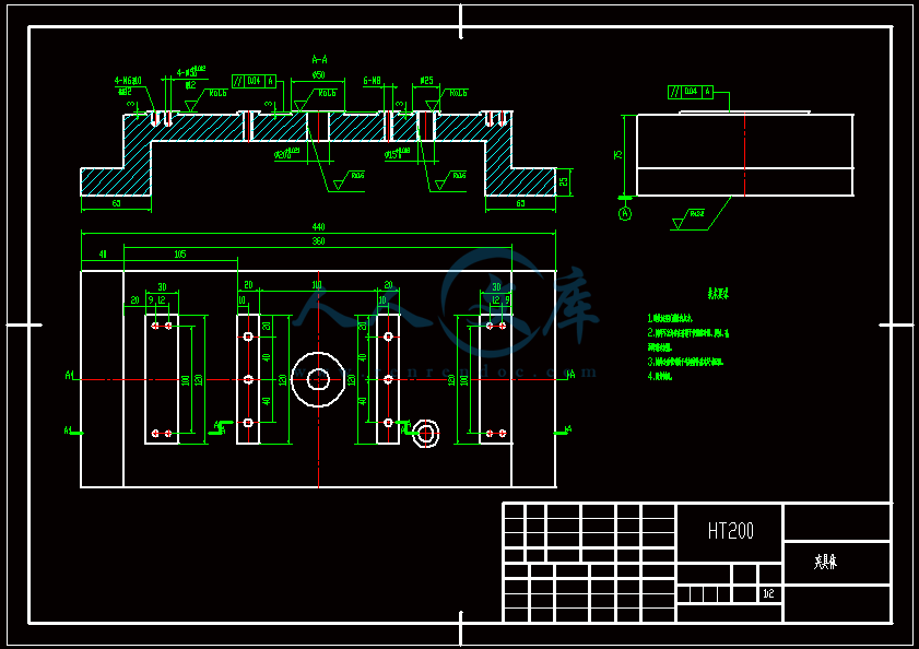
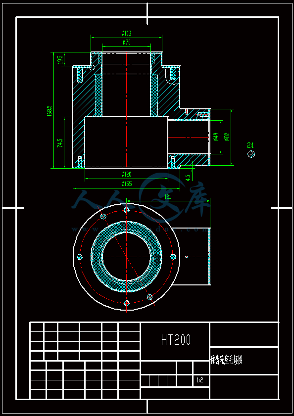
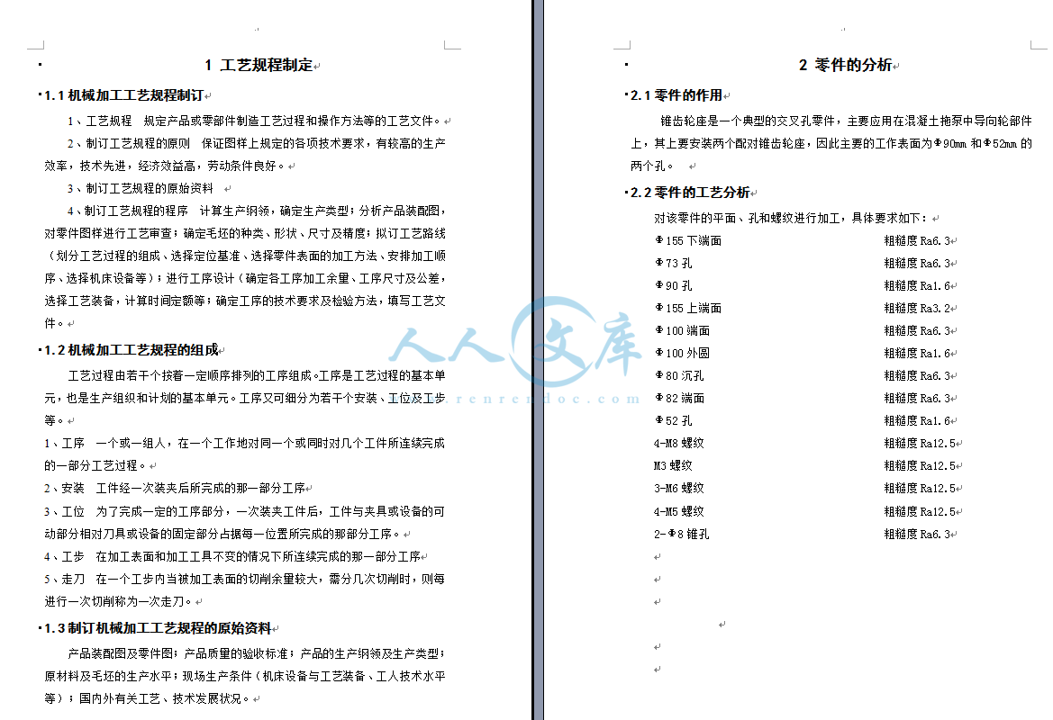
锥齿轮座零件机械加工工艺规程及钻、攻4-M8螺纹孔工装夹具设计(全套含CAD图纸)
收藏
资源目录

压缩包内文档预览:
编号:10158546
类型:共享资源
大小:2.17MB
格式:ZIP
上传时间:2018-06-04
上传人:机****料
认证信息
个人认证
高**(实名认证)
河南
IP属地:河南
20
积分
- 关 键 词:
-
齿轮
零件
机械
加工
工艺
规程
m8
螺纹
罗纹
工装
夹具
设计
全套
cad
图纸
- 资源描述:
-


- 内容简介:
-
, J.M.Superior2,Cranfieldaccepted26reliesrequirements, taking this as a general concept, is to makeshould be always linked to a requirement, and its purpose isInternational Journal of Machine Tools Fixture knowledge modelling, Fixture functional requirements1. IntroductionThe main objective of any design theory is to provide asuitable framework and methodology for the definition ofa sequence of activities that conform the design process of aproduct or system 1. In general, all of them identifyrequirements as the starting point in the design process. Infact, the engineering discipline dealing with product designcan be defined as the one that considers scientific andengineering knowledge to create product definitions anddesign solutions based on ideas and concepts derived fromrequirements and constraints 24.For this research, a relevant issue when consideringexplicit the meaning of two main terms: FunctionalRequirement (FR) and Constraint (C). A functionalrequirement, as it stated by different authors, representswhat the product has to or must do independently of anypossible solution, 2,4. A FR is a kind of requirement, andconsidering some basic principles widely recognized in thefield of Requirements Engineering, we could add it is aunique and unambiguous statement in natural language of asingle functionality, written in a way that it can be ranked,traced, measured, verified, and validated. A constraintcan be defined as a restriction that in general affects somekind of requirement, and it limits the range of possiblesolutions while satisfying the requirements. So, a constraintA functional approach for the formalizationR. Huntera, J. Riosb,*aDepartment of Mechanical and Manufacturing Engineering, Escuela TecnicaJose Gutierrez Abascal,bCurrently in Enterprise Integration (Bldg 53),Received 14 January 2005;Available onlineAbstractThe design of machining fixtures is a highly complex process thatof the fixture design processPereza, A. Vizanade Ingenieros Industriales, Universidad Politecnica de Madrid,28006 Madrid, SpainUniversity, Cranfield, MK43 0AL, UK14 April 2005August 2005on designer experience and his/her implicit knowledge to achieveManufacture 46 (2006) 683697/locate/ijmactoolfunctional requirements should be defined in the functionaldomain, which brings on the scene the issue of how to defineand represent the functionality of a product. The way used torepresent it will affect the reasoning process of the designer,and in that sense, the mapping between the functional0890-6955/$ - see front matter q 2005 Elsevier Ltd. All rights reserved.doi:10.1016/j.ijmachtools.2005.04.018* Corresponding author. Tel.: C44 1234 754936; fax.: C44 1234750852.to narrow the design outcome to acceptable solutions.Considering the Theory of Axiomatic Design 4,ably, the first aspect to think about is how the requirementsare represented or declared. As it has been previouslyand the physical domains, being the later the one where thedesign solutions are developed. Several authors haveinvestigated the concept of functionality and functionalrepresentation 2,58. Their design approach provides aview based on the Function-Behaviour-Structure frame-work, where function is defined using structure andbehaviour 6. The objective is to fill the gap that allowsa designer to progress from FRs to physical designsolutions. The approach is that product functions areachieved by means of its structure, which seems to lead toan iterative causal approach, where solutions are soughtuntil the selected structure causes the intended functionality.The approach adopted in the research presented in this paperis based on the definition of Fixture Functional Components(FFC), which can satisfy the fixture functionality, and on themapping between such FFC and fixture commercialelements.An advanced approach to the definition of requirementsand functions comes from the creation of ontologies. Theontological approach pursues the definition of the meaningof terms making use of some kind of logic, and the definitionof axioms to enable automatic deduction and reasoning 9.The ontological approach has got a higher relevance sincethe representation of knowledge is considered the key factorin whatever engineering process, and it has been recognizedas a way to facilitate the integration of engineeringapplications 10, to describe functional design knowledge7, and to define requirements 11. Considering a puristapproach, if an ontology does not include axioms to enablereasoning then it could be considered more like aninformation model, and in this sense, this is the approachdeveloped in the work presented in this paper.When considering the methodologies developed for thedesign of fixtures, it can be stated that in general they arerational and propose a series of steps to follow. For example,the methodologies proposed by Scallan and Henriksen 12,13, make use of this approach to describe in general termsthe information needed in each stage of the fixture designprocess. Basically, the importance of modelling in detailsuch information, which mainly is related to fixturerequirements, fixture functionality, fixture components,manufacturing resources, manufacturing processes, anddesign rules; resides on the possibility to automate thedesign process through the development of a knowledge-based application or system. It is relevant to mention thatseveral authors have already aimed to develop knowledge-based applications for fixture design, none of them based ona functional approach, some of the most recently publishedworks can be found in the Refs. 1419.In the following sections, this paper presents amethodology to formalize the design process of machin-ing fixtures based on the engineering concepts offunctional requirements and fixture functions 20. Theformalization of the functional requirements is achievedthrough the application of a structured way of specifica-R. Hunter et al. / International Journal of Machine684tion via natural language. Additionally, IDEF0, MOKAmentioned, the way of expressing requirements definitivelyaffects their interpretation and the creation of a designsolution. In this sense, it is widely accepted, that the use ofnatural language is the most common way of expressingrequirements and in consequence, their writing becomes animportant issue. The anatomy proposed by Alexander et al.24 to write requirements in a semi-structured way is usedas basis to declare the functional requirements andconstraints of fixtures 20.In machining, work holding is a key aspect, and fixturesare the elements responsible to satisfy this general goal. Intheir design process, the starting point is the definition of themachining fixtures functional requirements and constraints.Usually, a fixture solution is made of one or several physicalelements, as a whole the designed fixture solution mustmethodology, and UML diagrams are used to capture,represent and formalize knowledge, being the ultimategoal to facilitate the automation of the fixture designprocess.The IDEF0 method is used to create an activity model ofthe fixture design process, allowing the identification of theinformation used in each one of the different tasks itcomprises. UML has been used to complement the IDEF0model by representing the interaction between the activitiesof the process. The MOKA methodology together withUML, are used to capture and represent knowledge involvedin the fixture design process. Finally, to validate theproposed methodology, partial results obtained from thedevelopment of a prototype knowledge-based applicationare presented.2. Analysis of machining fixtures requirementsIn Section 1, two terms have been defined: functionalrequirement and constraint. Requirements have alwaysexisted, the way in which they are expressed, and howthey are integrated in the product design process, are aspectsthat are addressed from different disciplines, for example:product design engineering and requirements engineeringamong others. In general, Requirements Engineering refersto the discipline dealing with the capture, formalization,representation, analysis, management and verification ofrequirements fulfilment. However, all these aspects need tobe integrated in the product design process, and require-ments should lead to the definition of the possible productdesign solutions, which in general demands an integratedview of the requirements issue. It is important to keep inmind that the development of such discipline is stronglyrelated to Software Engineering and Systems Engineering,and in fact much of the research related to requirementscome from authors from these engineering areas 2123.When considering the analysis of requirements, prob-Tools in this case a KBE application forthe design of machining fixtures; and the second one is thefunctional requirements of the components subject of theapplication; in this case machining fixtures. An example ofthe former ones for an application developed in collabor-ation with an industrial partner is presented by Rios et al.28. For this kind of FRs specification, UML seems to befor fixture FRs.MOKA ICARE: ENTITYNameReferenceEntity TypeFunctionConstraints Functional Requirements for the FixtureConstraints Functional Requirements (CFR)StructureDefine constrains to Functional Requirements for the fixturet support the fune structurdeof the fixturRe03-07-041.0In progresformR. Hunter et al. / International Journal of Machine Tools it isindependent of the knowledge representation to be used inthe implementation, and it does not require from the fixturedesigner a deep knowledge of any software modellingtechnique.The definition of these fixture functions is a first step in themodelling needed for a KBE application development. Forexample, considering stability as one of the main constraintsaffecting the fixture FRs, any fixture functional solutionshould satisfy this constraint. To achieve that, it would benecessary to define a fixture function (FF) for stabilitymethodology.Part machining:operationsstrategiescutting parameterscutting tool parametersvolume to removeOptimization methodAnalysis modelConstraints:DeformationStabilityInterferencePart orientationPart support:support pointssupport vectorssupport surfacesDetermine cutDetermDetermine clDetermine clDetermDetermR. Hunter et al. / International Journal of Machine Tools & Manufacture 46 (2006) 683697 689Part location:locating pointslocating vectorslocating surfacesPart information:mechanical propertiesfriction coefficientraw material shape and dimensionspart shape and dimensionstolerancesevaluation, and this function could be called from the fixturefunction clamp (clamp_FF) presented as example in theFig. 6. From a high level perspective, the stability_FF wouldneed as input: part information (i.e.: material mechanicalproperties, shape, dimensions and tolerances), machiningprocess information (i.e.: machining operations, machiningstrategies, volumes to remove, cutting parameters, cuttingtool parameters), and fixture functional element information(i.e.: function, constraints, rules, containing volume, pointand vector of application). Part of this information will haveto be used to determine some derived parameters like cuttingand allowed clamping forces. Making use of such infor-mation together with an analysis model, for example the oneproposed by Liao et al. 32, and optimization methods, forexample the one proposed by Pelinescu et al. 33, suchstability_FF could be developed and implemented. Thecomplexity in the detailed specification of such stability_FFis extremely high, and demands its own research by itselfFig. 6. High-level function templateFig. 7. Structure of the AFNOR fixtureFixture functional elements:functionconstraintsrulescontaining volumeFunction Clamp(clamp_FF)F4ting forcesine clamping surfaceamping pointsamping orientationine clamping forcesine clamping elements32,34,35, but the definition of a high level function whereall the information needed for its development could berepresented, is one of the objectives of the research presentedin this paper.Phase 3: The third phase, functional design (FD), isaimed to create a set of functional solutions for the fixturedesign. A functional solution is independent of anyparticular commercial fixture component, and it is rep-resented by means of a set of fixture functional elements. Afixture functional element satisfies at least one of thefunctions identified as inherent to a fixture, i.e.: centre,position, orientate, clamp, and support. These elements arerepresented by means of graphical symbols, also calledfunctional symbols, which apart from the functionality alsorepresent some qualifiers that affect them. Such fixturefunctional symbols are based on the technological elementsdefined in the AFNOR standard NF E 04-013 - 1985 36.Fig. 7 presents their structure, which comprises: kind ofrepresentation.technological elements.Type Function*Surface class: Machined*Type contact surface: Punctualtechnology, state of the part surface, function of thetechnological element, and the kind of contact betweenthe part surface and the fixture element.In order to progress from the functional design to thedetailed one, which is the next phase, it has been defined amapping table between functional symbols and commercialfixture elements 20, Table 2 represents an example.For the creation of the possible functional solutions a setof input information, analysis models, optimization func-tions, and rules has to be included in the software functionspreviously defined in the second phase. Basically, the inputsdefined are: Part information: material mechanical properties, shapeand dimensions of the part to be machined, and theassociated tolerances. Functional element information: functions, associatedrestrictions, orientation, containing volume, contactparameters, and location point. Part manufacturing process: sequence of operations, andfor each operation: machining strategy, cutting para-meters, cutting tool, and volume to remove. Production estimation of: number of set-ups, set-uptimes, batch size, production rate, and target cost. Resource information: machine morphology, andmachine capacity.Functional design brings benefits to design environmentsTable 2Relation between AFNOR elements and fixture commercial componentsFixture function Functional representationClamp function(Attribute)Type technologySurface Class*Type technology*Surface class*Type contact surface*Type functionR. Hunter et al. / International Journal of Machine690where the solution is mainly driven by the satisfaction ofquantitative functions, as opposite to environments wheresubjective aspects like aesthetics has a major relevance. Inparticular, in the fixture design environment, the advantageof creating a functional solution derives from not using afull library of commercial fixture elements but a reducednumber of basic functional elements, which can betransformed into the former ones in a second designphase. And this is particularly relevant when some kind ofartificial intelligence technique is going to be applied in theimplementation phase, since many of these techniques arebased on the initial generation of a complete design spacewhere the possible solutions are contained, if the designspace can be reduced then the determination of the solutionscan be done more efficiently. And with the functional designapproach the design space is divided in two subsets, onesubset dealing with the functional solution and other dealingwith the physical one.Phase 4: The fourth phase, detailed design (DD)comprises the creation of detailed solutions from afunctional one. To undertake this phase the mapping tablespreviously mentioned and the corresponding interpretationrules have to be used. To mention as well, that the fixturesoftware functions apply in a similar way, but with adifferent input, which basically is the geometry (containingvolume) associated with the fixture element, this isparticularly relevant for the interference checking. How-ever, in this case the space of possible solutions is reducedby the fact that only those commercial elements that can bemapped to the functional ones can be used, and that a pointof application and an orientation vector for the elements tobe used are data as well. A detailed solution contains thefinalfixturecommercialelementstobeusedinthemachining of the part and their set-up.Finally, the fifth phase, validation of the design (FV), isaimed to make a final evaluation and validation of thefunctional requirements and their associated constraintsdefined in the first phase. However, it is important to mentionthat in addition to a final validation, the functional approach,with the separation of the design spaces in two parts, allowsimplementing the validation in two prior stages. First in thefunctional design phase, so the possible functional designType contact surface*Type function: Machining FixtureCommercial elements selected type*Type technology: ClampTools & Manufacture 46 (2006) 683697solutions fulfil the imposed requirements, and second in thedetailed design phase. This can be made by means of theoptimization method that can be included in the FixtureFunction (FF), as it was previously mentioned in the Phase 3.Based on this methodology, a detailed definition of thefixture functional design process is presented in the nextsection.4. Fixture functional design process modelAs it was mentioned in the introduction, the functionalapproach to design has drawn the attention of severalresearchers 2,5,6,7,8. However, as it is pointed out byKitamura 7, in general, the functional knowledge is leftimplicit, there are not clear definitions of the functionalconcepts, and the generic functions proposed in theliterature are too generic to be used by designers. In thissense, the ontological approach is an interesting contri-bution to formalize the functional desig
- 温馨提示:
1: 本站所有资源如无特殊说明,都需要本地电脑安装OFFICE2007和PDF阅读器。图纸软件为CAD,CAXA,PROE,UG,SolidWorks等.压缩文件请下载最新的WinRAR软件解压。
2: 本站的文档不包含任何第三方提供的附件图纸等,如果需要附件,请联系上传者。文件的所有权益归上传用户所有。
3.本站RAR压缩包中若带图纸,网页内容里面会有图纸预览,若没有图纸预览就没有图纸。
4. 未经权益所有人同意不得将文件中的内容挪作商业或盈利用途。
5. 人人文库网仅提供信息存储空间,仅对用户上传内容的表现方式做保护处理,对用户上传分享的文档内容本身不做任何修改或编辑,并不能对任何下载内容负责。
6. 下载文件中如有侵权或不适当内容,请与我们联系,我们立即纠正。
7. 本站不保证下载资源的准确性、安全性和完整性, 同时也不承担用户因使用这些下载资源对自己和他人造成任何形式的伤害或损失。

人人文库网所有资源均是用户自行上传分享,仅供网友学习交流,未经上传用户书面授权,请勿作他用。
|
2:不支持迅雷下载,请使用浏览器下载
3:不支持QQ浏览器下载,请用其他浏览器
4:下载后的文档和图纸-无水印
5:文档经过压缩,下载后原文更清晰
|
 川公网安备: 51019002004831号