Laser cuttingofsharpedge Thermalstressanalysis.pdf
三轴联动激光切雕一体机设计【原创含7张CAD图带开题报告】
收藏
资源目录

压缩包内文档预览:
编号:10234902
类型:共享资源
大小:11.28MB
格式:ZIP
上传时间:2018-06-25
上传人:QQ14****9609
认证信息
个人认证
郭**(实名认证)
陕西
IP属地:陕西
100
积分
- 关 键 词:
-
联动
激光
一体机
设计
原创
cad
开题
报告
讲演
呈文
- 资源描述:
-
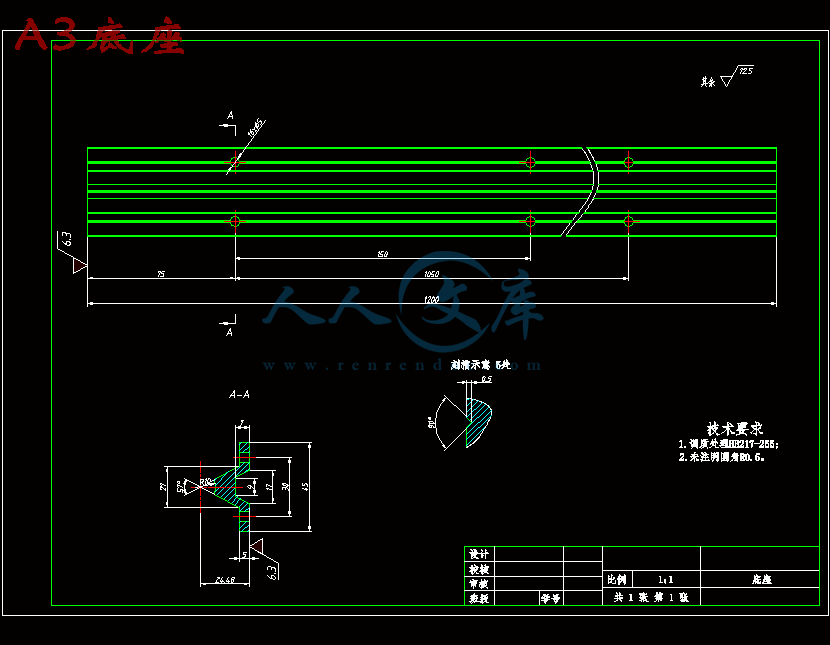
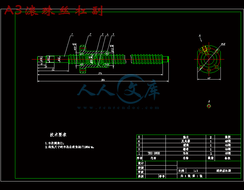
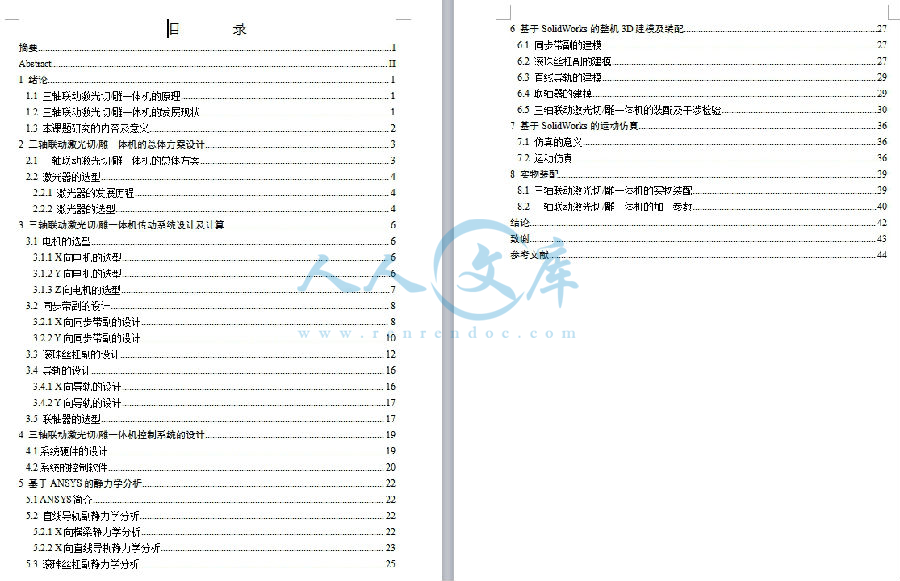
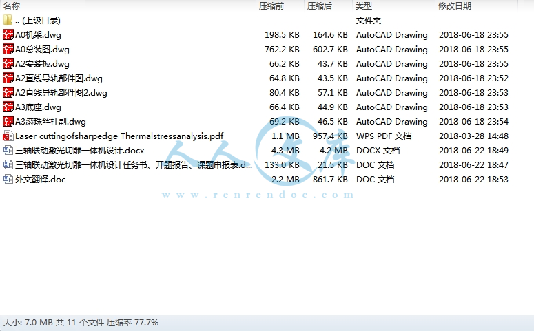
三轴联动激光切雕一体机设计【含7张CAD图带开题报告】
【需要咨询购买全套设计请加QQ1459919609】图纸预览详情如下:
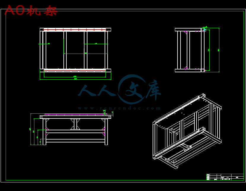
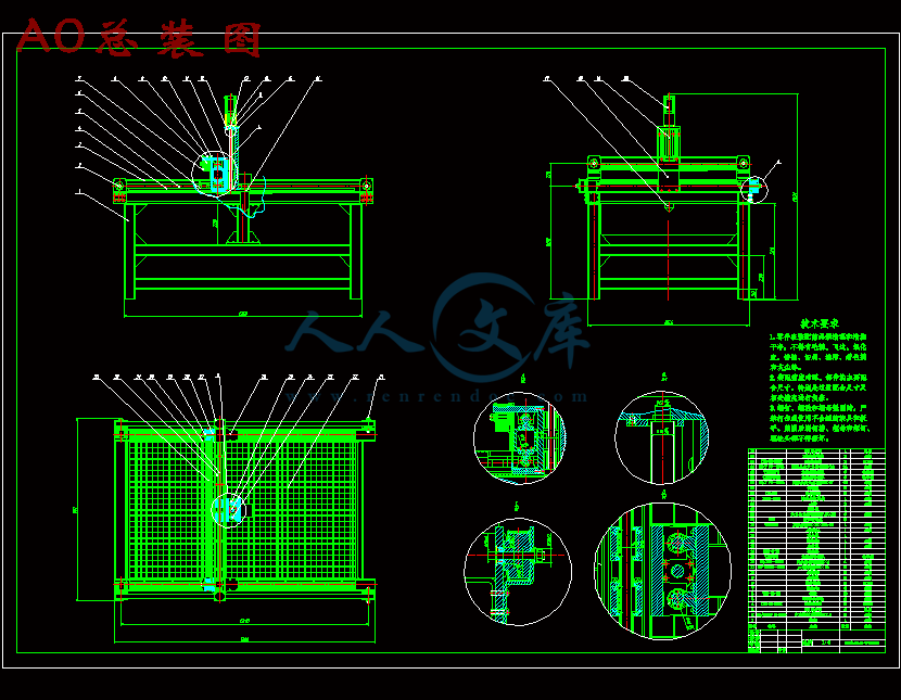

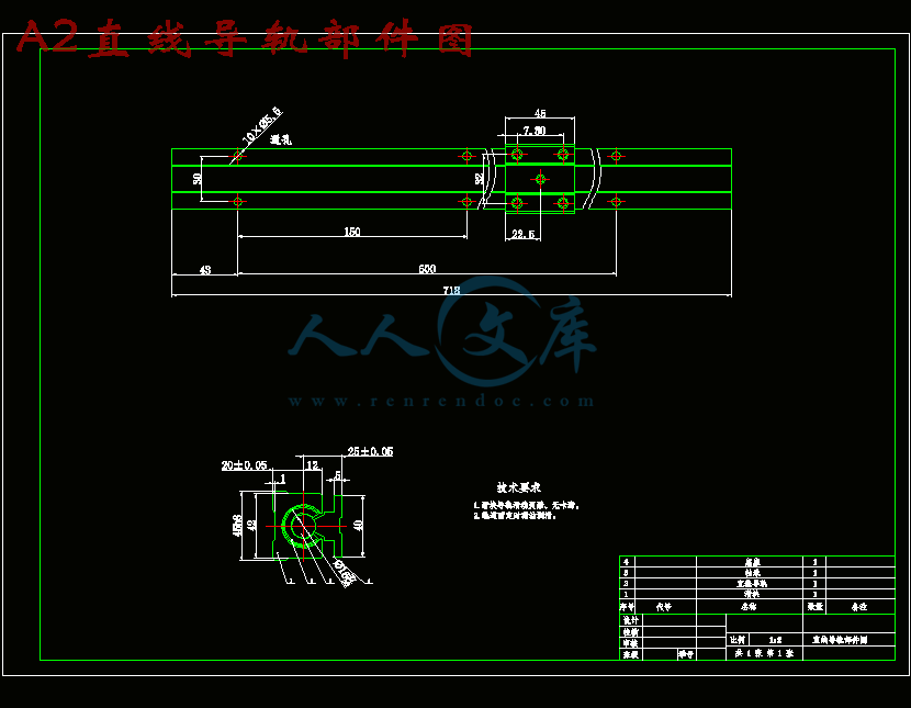
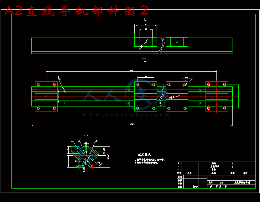
- 内容简介:
-
essandureulationsnedremainsMPawayalues.diateds contributis particularthis case,limitsinvestigedgesre carriedsing.was introduced by Aloke et al. 3. They assumed that the laserlasertoenhance the thermal stresses for driving a propagating crackARTICLE IN PRESSContents lists available at ScienceDirectOptics and LasersOptics and Lasers in Engineering 48 (2010) 1019field. Hardjadinata and Doumanidis 11 introduced a new solidE-mail address: bsyilbas.sa (B.S. Yilbas).adjacent to the hole was plastically deformed and contained thealong a pre-ordained path using simultaneous CO2laser. Lasercleaving of a soda-lime glass substrate was investigated by Kuoand Lin 10. They introduced uncoupled thermal-elastic analysisbased on the finite element method (FEM) to model the stress0143-8166/$-see front matter fax: +99638602949.of the heat affected zone and on the resulting residual stresses. Aphysical model for thermal effects during laser cutting of holescontrol fractures for the fast laser machining of lamina plates.They accommodated the simultaneous scoring technique toaffected zone and residual stress distribution during laser cuttingof the thin sheet plates was carried out by Li and Sheng 2. Theyanalyzed the effects of cutting speed and laser power on the sizeand the model developed was integrated with a probabilisticfracture model to assess the failure probability during thecutting process. Brugan et al. 9 introduced a new methoddetermining the stress levels and fracture during the laser cuttingof ceramics was investigated by Li and Sheng 1. They introduceda hybrid model to predict the fracture initiation while a numericalapproach adopting a plane stress model was employed for thestress analysis. The numerical study for predictions of heatfunction method while accommodating stress evolution duringthe heating and cooling cycles. A model study incorporating theablation process and the thermal stress evolution during the lasercutting of ceramics was carried out by Akarapu and Seqall 8.They used a fixed grid algorithm to model the ablation processwith high temperature, the temperaturlaser processed region attains high vthermal stress generation in the irrahigh cooling rates after the procesformation in this region. This situationcutting of sharp edges or corners. Ingenerated in the edges and cornersthe parts produced. Consequently,stress fields in laser cutting of sharpessential.Considerable research studies welaser cutting and the thermal procest developed in theThis, in turn, results inregion. In addition, thees to the stressly true for laserthe residual stressthe practical usage ofation of thermal andand corners becomesout to examine theThe plane stress modelthermal field induced by the heat source tends to close thesurfaces of the cut in the vicinity of the tip. The elastic thermalstress model was used to predict the stress field during the laserprocessing of ceramics by Modest and Mallison 5. Theypredicted the elastic stress fields as developed and decayedduring the laser processing. The laser cutting technique by acontrolled fracture was introduced by Tsai and Chen 6. Theyused the Nd:YAG laser to scribe a groove crack on the surface ofthe substrate material while using a defocused CO2laser beam togenerate the thermal stresses. A high-speed laser cutting ofthermoplastic films was investigated by Coelho et al. 7. Theysolved the heat transfer equation analytically by the Greenand a precision of operation. Since the laser processing is involvede gradienthe stress intensity factors were negative, which meant that theLaser cutting of sharp edge: Thermal strB.S. YilbasC3, A.F.M. Arif, B.J. Abdul AleemME Department, KFUPM, Dhahran 31261, Saudi Arabiaarticle infoArticle history:Received 22 November 2008Received in revised form28 February 2009Accepted 1 March 2009Available online 20 August 2009Keywords:LaserCuttingSheet metalThermal stressabstractLaser cutting of sharp edgefinite element method is usedtechnique is used to measthickness is used in the simaround the edges are examiis found that temperatureThis, in turn, lowers the coolingresidual stress is about 90of 280MPa, which occurs athe experimental data.1. IntroductionLaser processing of sheet metals finds wide application inindustry. The high energy focused beam provides a fast processingjournal homepage: analysisthermal stress development in the cutting section is examined. Theto predict temperature and stress fields while the X-ray diffraction (XRD)the residual stress around the cut edges. A mild steel sheet with 5mmand the experiment. The morphological and metallurgical changesusing the optical microscopyand scanning electron microscopy (SEM). Ithigh at the sharp edge when the laser beam is located in this region.rate and reduces von Mises stress in this region. The magnitude of theat the sharp corner while the maximum von Mises stress is in the orderfrom sharp corner. In addition, the residual stress predicted agrees withtherefore,evaporative heat transfer taking place at the free surface has notsignificant affect on temperature field in the vicinity of thesolidliquid interface. Since the thermal stress is only developedwithin the solid phase of the substrate material during the cuttingprocess, the transient heat diffusion equation based on the Fouriermodel, with the appropriate boundary conditions, can be applic-able to describe temperature field in the solid. Temperature fieldcan be coupled with the thermo-mechanical response of thematerial to determine the thermally induced stresses in thecutting section during the laser processing. The transient heatdiffusion equation can be written in the Cartesian coordinatesystem asrDEDtrkrT So(1)where E is the energy gain by the substrate material,r(k(rT) (q/qx)(k(qT/qx)+(q/qy)(k(qT/qy)(q/qz)(k(qT/qz) (x, yand z are the axes (Fig. 1a), and Sois the volumetric heat sourceterm. The laser heating source is assumed to be Gaussian at thesurface (x,y)-plane with the Gaussian diameter a and the beamis absorbed in the absorption depth along the y-axis within thesurface region. The volumetric source isSo Iod1C0 rfeC0dzeC0x2y2=a2(2)Iois laser peak intensity, d is the absorption depth, rfis thetccooling period (ms)trpulse rise time (ms)tfpulse fall time (ms)u laser cutting speed (m/s)dU strain energy (J)duTvector for virtual displacements (m)dV external work (J)w workpiece thickness (m)x,y,z space coordinatesGreek Symbola vector of coefficients of thermal expansion (1/K)eth thermal strain vectord absorption coefficient (1/m)r density (kg/m3)surface reflectivity, and x and z are the axes. However, the laserheating situation can be represented through consecutive pulsesresembling the duty cycle of the laser output power. In this case,the temporal variation of the laser pulse shape is resemblesalmost the actual laser pulse shape used in the experiment (50%duty cycle), which is in trapezium shape in time domain. The laserpulse parameters used in the simulations are given in Table 1while Fig. 1b shows the temporal variation of consecutive laserpulses. The time function (f(t) representing the consecutivepulses isft0; t 01; trttp0; t tp0; tpttp tc8:9=;(3)where tris the pulse rise time, tfis the pulse fall time, tpis thepulse length, tcis the end of cooling period. f(t) repeats when thesecond consecutive pulse begins, provided that time t tf+tccorresponds to the starting time of the second pulse. The samemathematical arguments can apply for the other consecutivepulses after the second pulse.In the case of a moving heat source along the x-axis with aconstant scanning speed u (Fig. 1), energy gain by the substratematerial yieldsrDEDt rEtC0ruEx(4)where qE/qt (q(CpT)/qt) and qE/qx (q(CpT)/qx)orrDEDt rCpTtC0ruCpTx(5)Combining Eqs. (1) and (5) yieldsrCpTt rkrTruCpTx So(6)It should be noted that in the cutting analysis, the reflection ofthe laser beam from the cut edges are omitted, since internalreflection is absorbed by the cutting surface. Therefore, thereflection loss from the irradiated laser beam only occurs fromthe free surface of the substrate material. Moreover, at the freesurfaces of the workpiece (the irradiated surface), the convectiveboundary is assumed and at the rear side of the workpiece, theconvective and radiative boundary condition is considered.Therefore, the corresponding boundary condition isAt the free surface (in xy plane at z 0) a convectiveboundary is assumed, therefore, the corresponding boundarycondition isAt z 0 at the surface!TzhkTsC0 Towhere h is the heat transfer coefficient and Tsand Toare thesurface and reference temperatures, respectively. In addition, at adistance far away from the surface in the xy plane temperaturebecomes the same as the reference temperature. This yields theboundary condition ofAt x and y 1!T T1To;SpecifiedARTICLE IN PRESSz = 0u - Laser cutting velocityWorkpiecexyz B.S. Yilbas et al. / Optics and Lasers in Engineering 48 (2010) 101912Duty Cycle = 0.50.00.51.01.50.00TIME (ms)RELATIVE INTENSITYtB= Begining of Heating CycletE= Ending of Heating CycletBtEtrtftptcz = waLaser heat sourceLaser cut edgew0.50 1.00 1.50 2.00 2.50Fig. 1. (a) A typical laser cutting situation and coordinate system. w is theworkpiece thickness. (b) Two consecutive pulses with a 50% duty cycle. It shouldbe noted that 50% duty cycle is used in the cutting experiments.Table 1Laser pulse parameters used in the simulations.Duty cycle Laser pulselength, tp(ms)Cooling period,tc(ms)Pulse rise time,tr(ms)50% 0.5 0.5 0.065The thermo-mechanical phenomenon of laser cutting isidealized as a sequentially coupled unidirectional problem. Forthe thermo-mechanical coupling situation which does not exhibita high degree of nonlinear interaction, the load transfer method ismore efficient and flexible due to that one can perform the twoanalyses independently from each other 20. Therefore, a loadtransfer thermal stress analysis is performed involving a nonlinearPulse fall time,tf(ms)Pulse intensity(W/m2)C2109Guassian parameter,a (m)C210C040.0325 1 2.997For structural response, the finite element formulation is basedon the principle of virtual work. From the principle of virtual work(PVW), a virtual (very small) change of the internal strain energy(dU) must be offset by an identical change in external work due tothe applied loads (dV). Considering the strain energy due tothermal stresses resulting from the constrained motion of a bodyduring a temperature change, PVW yieldsfdugTZvolBC138TDC138BC138dvfugfdugTZvolBC138TDC138fC15thgdv (7)Noting that the du T vector is a set of arbitrary virtualdisplacements common in all of the above terms, the conditionrequired to satisfy above equation reduces toKC138fugfFthgwhereKC138ZvolBC138TDC138BC138dv element stiffness matrixfFthgZvolBC138TDC138fC15thgdv element thermal load vectorfC15thgfagDT thermal strain vectorfagvector of coefficients of thermal expansionvon Mises stress can be computed from the stress tensor, whichis defined ass 32sijsijq(8)where sijare the components of the stress deviator tensor.4. Finite element simulationInitially the substrate material is assummed to be at a referencetemperature (To), therefore, the initial condition becomesAt t 0 ! T T1To;SpecifiedThe finite difference method is used to discretize Eq. (6). Explicitscheme is used to compute temperature field. The grid indepen-dent tests are conducted to secure the grid independent results.3. Modeling of thermal stressestransient thermal analysis followed by a static stress analysis. Thetwo fields are coupled by applying results from one analysis asloads in another analysis. Utilizing the ANSYS APDL programminglanguage, separate thermal and stress analysis files were createdusing a single finite element mesh with different element types.The computation process was to read in the first physics file forthermal analysis and to solve. Then, the next physics field wasread for stress analysis specifying the loads to be transferred, andsolved the second physics. In the current work, the nodaltemperatures from the thermal analysis are applied as bodyforce loads in the subsequent stress analysis. For thermalanalysis, the given structure is modeled using thermal element(SOLID70). SOLID70 has a 3-D thermal conduction capability. Theelement has eight nodes with a single degree of freedom,temperature, at each node. The element is applicable to a 3-D,steady state or transient thermal analysis. Since the modelcontaining the conducting solid element is also to be analyzedstructurally, the element is replaced by an equivalent structuralThe moving heat source is modeled as a moving source at thenozzle and co-axially with the laser beam is used. Focal lens of127mm is used to focus the laser beam. The laser cuttingparameters are given in Table 3.JEOL JDX-3530 scanning electron microscope is used to obtainphotomicrographs of the cross section and surface of the work-pieces after the tests. The Bruker D8 Advance having MoKaradiation is used for XRD analysis. A typical setting of XRD wasARTICLE IN PRESScycle0300600900120020DISTANCE ALONG Y-AXIS (cm)TEMPERATURE (K)x = 3.22 cm : z = 0 cm and Laser Beam is at Bx = 6.52 cm : z = 0 cm and Laser Beam is at O050010001500200020DISTANCE ALONG Y-AXIS (cm)TEMPERATURE (K)x = 3.30 cm : z = 0 cm and Laser Beam is at Bx = 6.30 cm : z = 0 cm and Laser Beam is at O21 21 22 22 2321 21 22 22 23Fig. 2. Temperature variation along the y-axis at two locations on the cut edge.(3.3 cm, 22.8 cm)Location By-axis(6.6 cm, 20 cm)(1.65 cm, 20 mm)Location OLocation Ax-axis (cm)z-axis (cm)Cutting DirectionB.S. Yilbas et al. / Optics and Lasers in Engineering 48 (2010) 1019 13cutting edge resulting in a specified temperature greater than thesubstrate melting temperature. Using the specified laser speedand the finite element mesh size, time step was calculated for thethermal analysis. At each incremental time step, the specifiedtemperature for the heat source was moved to the next adjacentset of nodes using APDL DDELE and D commands 16. DDELEcommand deletes degree of freedom constraints. However,deleting a constraint in ANSYS is not the same as setting it tozero. Deleting a constraint has the same effect as deactivating,releasing, or setting the constraint free.The mechanical and thermal properties used in the currentsimulations are given in Table 2. It should be noted that theconditions for the current simulations resemble the actualexperiments carried out in the present study.5. ExperimentalThe laser used in the experiment is a CO2laser (LC-aIII-Amada)and delivering nominal output power of 1800Wat the pulse modewith adjustable frequencies. Nitrogen emerging from a conicalTable 2Thermal and mechanical properties of mild steel used in the simulations.k (W/mK) 63Cp (J/kgK) 420r (kg/m3) 7860a (m2/s) 1.6134E-5Tm(K) 1700aT(1/K)C210C0615n 0.29E (GPa) 210Table 3Laser cutting parameters.Feed rate (m/s) Power (W) Frequency (Hz) Nozzle gap (mm) Duty0.1 1800 1000 1.5 50%element (such as SOLID45) for the structural analysis. SOLID45 isused for the 3-D modeling of solid structures. The element isdefined by eight nodes having three degrees of freedom at eachnode: translations in the nodal x, y, and z directions. The elementhas plasticity, creep, swelling, stress stiffening, large deflection,and large strain capabilities.Nozzle diameter (mm) Focus diameter (mm) N2pressure (kPa)1.5 0.3 600Fig. 3. The cutting geometry used in the simulations and the experiment. Thethickness is 5mm.ARTICLE IN PRESSB.S. Yilbas et al. / Optics and Lasers in Engineering 48 (2010) 10191440kV and 30mA. It should be noted that the residual stressmeasured using the XRD technique provides the data in thesurface region of the specimens. This is because of the penetrationdepth of MoKa radiation into the coating, i.e. the penetrationdepth is in the order of 1020mm. The measurement relies on thestresses in fine grained polycrystalline structure. The position ofthe diffraction peak undergoes shifting as the specimen is rotatedby an angle c. The magnitude of the shift is related to themagnitude of the residual stress. The relationship between theFig. 4. (a) Temperature distribution around the cut edges when laser beam is at locationlocation O.peak shift and the residual stress (s) is given 21s E1usin2cdnC0 dodo(9)where E is Youngs modulus, n is Poissons ratio, c is the tilt angle,and diare the d spacing measured at each tilt angle. If there are noshear strains present in the specimen, the d spacing changeslinearly with sin2c.B. (b) Temperature distribution around the cut edges when laser beam is atresults in higher the stress gradients. In addition, change in thetemperature gradient along the y-axis results in the shift of thelocations (A and B, Fig. 3) along the cutting edge. It should benoted that the x- and y-axes locations are the locations of the laserbeam axis. Consequently, the maximum temperature is limitedwith the melting temperature of the substrate material.Temperature rises rapidly reaching the melting temperature andfirst decays sharply and later gradually. The sharp decay intemperature is because of the high cooling rates due to thediffusional energy transfer from the heated region to the solidbulk. In the case of the point B, the cooling rate (qT/qt) is slightlylower than that corresponding to the point A. This is particularlytrue in the time domain when temperature decay is gradual. Thisis because of the small surface area of the sharp corner, whichsuppresses the amount of energy diffused from this region to thesolid bulk through conduction. Moreover, temperature reducesbelow 500K for time tX2s. In this case, the stress developed inthese regions becomes the residual stress after this time period.Fig. 8 shows temporal variation of von Mises stress at the samelocation of Fig. 7. The
- 温馨提示:
1: 本站所有资源如无特殊说明,都需要本地电脑安装OFFICE2007和PDF阅读器。图纸软件为CAD,CAXA,PROE,UG,SolidWorks等.压缩文件请下载最新的WinRAR软件解压。
2: 本站的文档不包含任何第三方提供的附件图纸等,如果需要附件,请联系上传者。文件的所有权益归上传用户所有。
3.本站RAR压缩包中若带图纸,网页内容里面会有图纸预览,若没有图纸预览就没有图纸。
4. 未经权益所有人同意不得将文件中的内容挪作商业或盈利用途。
5. 人人文库网仅提供信息存储空间,仅对用户上传内容的表现方式做保护处理,对用户上传分享的文档内容本身不做任何修改或编辑,并不能对任何下载内容负责。
6. 下载文件中如有侵权或不适当内容,请与我们联系,我们立即纠正。
7. 本站不保证下载资源的准确性、安全性和完整性, 同时也不承担用户因使用这些下载资源对自己和他人造成任何形式的伤害或损失。

人人文库网所有资源均是用户自行上传分享,仅供网友学习交流,未经上传用户书面授权,请勿作他用。
|
2:不支持迅雷下载,请使用浏览器下载
3:不支持QQ浏览器下载,请用其他浏览器
4:下载后的文档和图纸-无水印
5:文档经过压缩,下载后原文更清晰
|
 川公网安备: 51019002004831号