基于plc自动运料皮带运输系统的设计(含CAD图纸源文件)
收藏
资源目录

压缩包内文档预览:(预览前20页/共51页)
编号:10239516
类型:共享资源
大小:11.75MB
格式:ZIP
上传时间:2018-06-26
上传人:机****料
认证信息
个人认证
高**(实名认证)
河南
IP属地:河南
50
积分
- 关 键 词:
-
基于
plc
自动
皮带
运输
系统
设计
cad
图纸
源文件
- 资源描述:
-


- 内容简介:
-
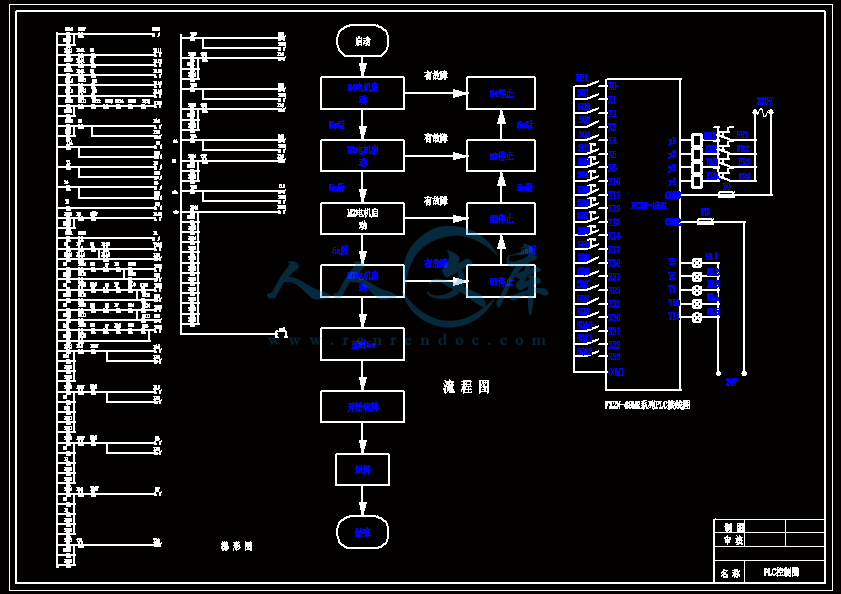
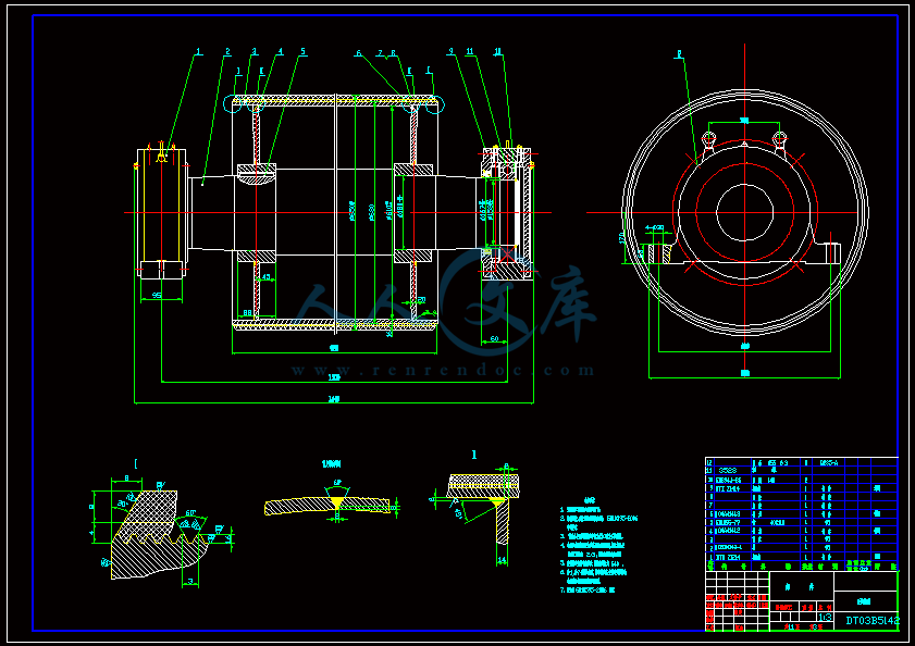
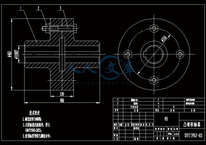
下载后文件包含有 CAD 图纸和说明书,咨询 Q 197216396 或 11970985I摘 要本系统主要是对自动运煤皮带运输机进行控制设计。输煤皮带控制系统的设计是一个很传统的课题,现在随着各种先进精确的诸多控制仪器的出现,输煤皮带控制的设计方案也越来越先进,越来越趋于完美,各种参考文献也数不胜数。该系统用三菱 FX2N 系列可编程序控制器( PLC)作为控制核心,整个系统采用了一台 PLC 控制 4 台皮带机,整个控制系统设一个控制室。利用 PLC 控制皮带输煤机,实现了逆序启动、顺序停止、故障停止、紧急停止的功能,并且有手动控制和自动控制两种控制方式,从而实现了输煤系统的自动化功能。本文对 PLC 自动运料皮带运输机控制系统进行了详细的研究,该控制系统具有精度高、成本低、抗干扰能力强、故障率低、操作维护简单等特点,具有良好的应用价值。本次设计主要的内容:采用三菱 FX2N 系列 PLC 实现控制系统的设计,着重从皮带运输机方面深入研究,确定其控制要求,明确 PLC 的机型的选择,确定 I/O 地址的分配,设计 I/O 接线图、控制流程图及梯形图,深入理解 PLC 的编程方法,按照控制要求对自动配料皮带运输机系统进行编程。关键词:皮带运输机;可编程控制器;控制下载后文件包含有 CAD 图纸和说明书,咨询 Q 197216396 或 11970985IIAbstractThis system is mainly to control the automatic coal belt conveyor design.Design of the control system of coal conveying belt is a very traditional subject, now with the emergence of of all kinds of advanced precise control instruments, the design scheme of coal conveying belt control is becoming more and more advanced, more and more tend to be more perfect, all sorts of reference also. The system with mitsubishi FX2N series programmable controller (PLC) as control core, the system adopted a PLC control 4 belt machine, the whole control system set up a control room. Using PLC control coal conveyer belts, realized the reverse order start, stop, fault stop, emergency stop function, and there are two kinds of control mode, manual control and automatic control so as to realize the automation of the coal conveying system function.In this paper, the PLC automatic material handling a detailed study of the belt conveyor control system, the system is composed of two parts: automatic material handling equipment and belt conveyor control system. The control system has high precision, low cost, strong anti-interference ability, low failure rate, simple operation and maintenance etc., has a good application value.This design main content: the design of the control system of mitsubishi FX2N series PLC, in-depth study emphatically from the aspects of belt conveyor, determine its control requirement, clear PLC model selection, determine the allocation of I/O address, the design of I/O wiring diagram and control flow diagram and ladder diagram, deep understanding of the PLC programming method, carried out in accordance with the requirements for automatic batching belt conveyor system programming.Keywords : Belt conveyor;PLC;Control下载后文件包含有 CAD 图纸和说明书,咨询 Q 197216396 或 11970985III目 录摘要 .IAbstract.II第 1 章 绪论 .11.1 皮带运输机的概况 .21.1.1 皮带运输机的发展史 .21.1.2 矿用皮带运输机各机型介绍.21.1.3 皮带运输机基本结构 .21.1.4 皮带运输机的调试 .31.1.5 传送带常见故障 .31.1.6 四级传送带视图分析 .41.2 皮带运输机的发展趋势 .41.2.1 国外皮带运输机技术的现状.41.2.2 国内皮带运输机技术的现状.51.2.3 煤矿皮带运输机技术的发展趋势 .6第 2 章 皮带运输机的设计计算 .72.1 已知原始数据及工作条件.72.2 输送带宽度的确定及核算.72.2.1 带速的确定.72.2.2 带宽的确定.82.2.3 输送带宽度的核算 .102.3 圆周驱动力 .102.3.1 计算公式 .102.3.2 主要阻力计算 .112.3.3 特种主要阻力计算 .132.3.4 特种附加阻力计算 .132.3.5 倾斜阻力计算 .152.4 传动功率计算.152.4.1 传动滚筒轴功率计算 .152.4.2 电动机功率计算 .152.5 输送带张力计算 .162.5.1 阻力计算 .16下载后文件包含有 CAD 图纸和说明书,咨询 Q 197216396 或 11970985IV2.5.2 输送带不打滑条件校核 .192.5.3 输送带下垂度校核 .202.5.4 输送带强度校核计算 .212.6 拉紧力计算 .21第 3 章 传动装置的选用与设计 .233.1 电机的选用 .233.2 减速器的选用.243.2.1 传动装置的总传动比 .243.2.2 减速器的选用.243.3 传动滚筒 .263.3.1 传动滚筒的选型及设计 .263.3.2 传动滚筒筒体的设计 .263.3.3 传动滚筒轴的设计计算 .293.3.4 传动滚筒结构.303.3.5 传动滚筒的直径验算 .31第 4 章 控制系统的设计 .334.1 选择 PLC 的依据 .334.2 PLC 的基本组成 .334.3 PLC 的工作原理 .344.4 可编程序控制器的特点 .364.5 PLC 选型 .364.6 接线图 .384.6.1 PLC 接线图 .38第 5 章 可编程控制器程序编辑 .405.1 梯形图程序分析 .405.1.1 运煤皮带机循环自动启动程序分析 .405.1.2 运煤皮带机循环自动停止程序分析 .415.1.3 运煤皮带机单动启动与停止程序分析 .425.1.4 运煤皮带机故障停止程序分析.43结论 .46参考文献 .47致谢 .48下载后文件包含有 CAD 图纸和说明书,咨询 Q 197216396 或 11970985I下载后文件包含有 CAD 图纸和说明书,咨询 Q 197216396 或 11970985II下载后文件包含有 CAD 图纸和说明书,咨询 Q 197216396 或 119709851第 1 章 绪 论PLC 目前已广泛应用于工业生产的自动化控制领域,无论是从国外引进的自动化生产线,还是自行设计的自动控制系统,都普遍采用了 PLC 控制。PLC 控制系统始终处于工业自动化控制领域的主战场,为各种各样的自动化控制设备提供了非常可靠的控制应用。其主要原因,在于它能够为自动化控制应用提供安全可靠和比较完善的解决方案,适合于当前工业企业对自动化的需要。与传统的继电器控制相比,PLC 控制系统具有构成简单、可靠性高、通用性强、抗干扰能力强、易于编程,体积小、可在线修改、设计与调试周期短、便于安装和维修等突出优点、而且一般不需要采取特殊措施,就能直接在工业环境中使用,更加适合现代化的要求,使用 PLC 控制系统能够提高系统的整体性能,具有较明显的优越性。皮带运输机是广泛应用于煤炭、港口、建设、电厂等工业领域的连续输送设备,它具有运输效率高、运营成本低等优点。随着国民经济的发展,带式输送机的应用越来越广泛。近年来,随着工业技术的发展,带式输送机也不断朝着大运量、长距离、大倾角、高带速、投资费用少、运营费用低、工作可靠、维护方便等方向发展,对其设计技术的要求也越来越高。 为适应地形的要求,用输送带输送一定高度的带式输送机在很多方面有应用。本次毕业设计的主要内容:1.方案选择与系统结构设计;2.输入输出与 PLC 机型的选择;3.I/O 地址的分配;4.程序状态图的设计;5.梯形图的编写及程序分析。下载后文件包含有 CAD 图纸和说明书,咨询 Q 197216396 或 1197098521.1 皮带运输机的概况1.1.1 皮带运输机的发展史皮带运输机是由承载的输送带兼作牵引机构的连续运输设备,可输送矿石、煤炭等散装物料和包装好的成件物品。由于它具有运输能力大、运输阻力小、耗电量低、运行平稳、运输过程中对物料的损伤小、运营成本低等优点,被广泛应用于国民经济各部门。皮带运输机对建设现代化矿井有重要作用。皮带运输机是煤矿最理想的高效连续运输设备,与其他运输设备(如机车类)相比,具有输送距离长、运量大、连续输送等优点,而且运行可靠,易于实现自动化和集中化控制,尤其对高产高效矿井,皮带运输机已成为煤炭开采机电一体化技术与装备的关键设备。随着我国高产高效矿井的出现,原有的皮带运输机无论是主参数还是运行性能都已不能满足要求,必须向长距离、高带速、大运量、大功率的大型化方向发展,并要改善和提高运行性能,确保安全可靠。1.1.2 矿用皮带运输机各机型介绍(一) 固定高强度皮带运输机这是目前煤矿井下用量最多的一种机型,主要用于水平或倾角小于 18 的场合。由于受到输送带强度及零部件的限制,单机长度不宜过长,国内现在钢绳芯带最高为ST4000,整芯带为 PVG3150S,高强度机械接头要靠进口,为了降低胶带强度,减小驱动装置尺寸,国内外通常采用中间直线摩擦驱动和中间卸载式驱动,并采用软起动技术。国内现有近 10 种软起动方式,较好地解决了大型输送机的起动问题。(二) 可伸缩皮带运输机该机型主要用于煤矿采煤工作面顺槽输送原煤,当输送能力和运距较大时,可配中间驱动装置来满足要求。美国、德国、英国等国家的一些厂商公司都可为各种生产规模的高产高效工作面提供配套的顺槽用可伸缩皮带运输机。 (三) 压皮带运输机压皮带运输机也是为增大输送倾角而设计的,1979 年美国大陆输送机设备公司开始研制压皮带运输机,并于 1983 年研制出压带式大倾角皮带运输机 HAC,这台样机的输送倾角为 30 60 ,最大输送能力为 2 900 t/h,其压带是通过旋转的托辊组加载的。此后,大陆公司已生产 40 多台 HAC。19911994 年德国的 MAN TAKPR FODERTECHNIK 公司研制了 3 台用于卸船机的压皮带运输机。前苏联和日本等国也研制了这种皮带运输机。国内生产的压皮带运输机倾角可达 90 ,物料最大块度可达下载后文件包含有 CAD 图纸和说明书,咨询 Q 197216396 或 119709853300 mm。这种输送机由于本身结构的缺陷和经济上的原因,目前还没有在煤矿井下应用。1.1.3 皮带运输机基本结构皮带运输机的组成如图 1.1 所示,基本组成部分:输送带、托辊、驱动装置 (电动机、减速机、软起动装置、制动器、联轴器、逆止器、传动滚筒)、拉紧装置、清扫装置、机架、安全保护装置以及电气控制系统等组成。-头部漏斗 ;2-机架;3-头部扫清器;4-传动滚筒 5-安全保护装置;6- 输送带;7-承载托辊;8-缓冲托辊;9-导料槽;10-改向滚筒;11-拉紧装置 12-尾架;13- 空段扫清器;14-回程托辊;15-中间架;16-电动机;17-液力偶合器;18-制动器;19- 减速器;20- 联轴器图 1-1 皮带运输机组成示意图输送带绕经传动滚筒和机尾换向滚筒形成一个无极的环形带。输送带的上、下两部分都支承在托辊上。拉紧装置给输送带以正常运转所需要的拉紧力。工作时,传动滚筒通过它和输送带之间的摩擦力带动输送带运行。物料从装载点装到输送带上,形成连续运动的物流,在卸载点卸载。一般物料是装载到上带(承载段)的上面,在机头滚筒卸载,利用专门的卸载装置也可在中间卸载。1.1.4 皮带运输机的调试首先应检查运输机支架安装是否牢固,是否有遗漏的焊口,并逐个检查限位辊、张紧辊、导向辊的转动是否灵活,主动辊、从动辊内是否注油。以上确定无误后,采 取点动的方式启动主动辊电机,若继电器跳闸,切不可强行启动,应检查主动电机 内是否进入雨水造成短路,点动无误后,可正常启动主动辊电机。正常运转时,调整 皮带是本部工作中的 一个难点,若皮带跑偏,应调整尾部的可调螺母;若调整无效, 下载后文件包含有 CAD 图纸和说明书,咨询 Q 197216396 或 119709854则应检查导向辊的安装 是否正确 ,必要时,将导向辊一端 支架割开、移位、焊接。 如皮带过紧或过松,应调整张紧辊,使之松紧适宜。1.1.5 传送带常见故障a)传送带打滑传送带与皮带轮之间打滑为将这种打滑现象减到最低限度,建议驱动轮和被动轮都使用合适的防滑套。解决打滑问题可采取以下几点措施:(1)绷紧上下传送带;(2)检查紧带装置的调节机构是否需要加以紧固;(3)更换或磨粗现有的防滑套表面;(4)检查驱动齿轮的磨损情况。b)传送带与纸板之间打滑传送带与纸板之间打滑的主要原因是挂面纸板与热板之间产生的磨擦过大c) 其他故障 (1)过度的张力(2)传送带表面变光滑(3)切割刀的控制1.1.6 四级传送带视图分析当系统打开后,打开自动运行时,皮带运输机 M4 开始运行,待延时过后皮带机M3 开始运行,皮带机 M2 和皮带机 M1 也同样经过延时后开始运行,此后物料指示灯亮起,提示开始装煤。煤经过物料装置开始往传送带上输送,煤经过皮带机 M1 依次输送到皮带机 M4 上,然后输送到指定位置。Latest Developments in Belt Conveyor Technology M. A. Alspaugh Overland Conveyor Co., Inc. Presented at MINExpo 2004 Las Vegas, NV, USA September 27, 2004 Abstract Bulk material transportation requirements have continued to press the belt conveyor industry to carry higher tonnages over longer distances and more diverse routes. In order keep up, significant technology advances have been required in the field of system design, analysis and numerical simulation. The application of traditional components in non-traditional applications requiring horizontal curves and intermediate drives have changed and expanded belt conveyor possibilities. Examples of complex conveying applications along with the numerical tools required to insure reliability and availability will be reviewed. Introduction Although the title of this presentation indicates “new” developments in belt conveyor technology will be presented, most of the ideas and methods offered here have been around for some time. We doubt any single piece of equipment or idea presented will be “new” to many of you. What is “new” are the significant and complex systems being built with mostly mature components. What is also “new” are the system design tools and methods used to put these components together into unique conveyance systems designed to solve ever expanding bulk material handling needs. And what is also “new” is the increasing ability to produce accurate computer simulations of system performance prior to the first system test (commissioning). As such, the main focus of this presentation will be the latest developments in complex system design essential to properly engineer and optimize todays long distance conveyance requirements. The four specific topics covered will be: Energy Efficiency Route Optimization Distributed Power Analysis and Simulation Energy Efficiency Minimizing overall power consumption is a critical aspect of any project and belt conveyors are no different. Although belt conveyors have always been an efficient means of transporting large tonnages as compared to other transport methods, there are still various methods to reduce power requirements on overland conveyors. The main resistances of a belt conveyor are made up of: Idler Resistance Rubber indentation due to idler support Material/Belt flexure due to sag being idlers Alignment These resistances plus miscellaneous secondary resistances and forces to over come gravity (lift) make up the required power to move the material. 1Latest Developments in Belt Conveyor Technology MINExpo 2004, Las Vegas, NV, USA M.A. Alspaugh, Overland Conveyor Co., Inc. September 27, 2004 In a typical in-plant conveyor of 400m length, power might be broken into its components as per Figure 1 with lift making up the largest single component but all friction forces making up the majority. Power- In-PlantIdlers6%Rubber Indent11%Alignment9%Material Flexure21%Lift43%Miscellaneous10%Figure 1 In a high incline conveyor such as an underground mine slope belt, power might be broken down as per Figure 2, with lift contributing a huge majority. Since there is no way to reduce gravity forces, there are no means to significantly reduce power on high incline belts. But in a long overland conveyor, power components will look much more like Figure 3, with frictional components making up almost all the power. In this case, attention to the main resistances is essential. Power- Slope BeltLift90%Rubber Indent4%Idlers1%Alignment2%Material Flexure1%Miscellaneous2%Figure 2 The specifics of power calculation is beyond the scope of this paper but it is important to note that significant research has been done on all four areas of idlers, rubber indentation, alignment and material/belt flexure over the last few years. And although not everyone is in agreement as to how to handle each specific area, it is generally well accepted that attention to these main resistances is necessary and important to overall project economics. Power- OverlandRubber Indent48%Idlers26%Lift1%Alignment17%Material Flexure4%Miscellaneous4%Figure 3 At the 2004 SME annual meeting, Walter Kung of MAN Takraf presented a paper titled “The Henderson Coarse Ore Conveying System- A Review of Commissioning, Start-up and Operation”2. This project was commissioned in December 1999 and consisted of a 24 km (3 flight) overland conveying system to replace the underground mine to mill rail haulage system. Figure 4- Henderson PC2 to PC3 Transfer House Latest Developments in Belt Conveyor Technology MINExpo 2004, Las Vegas, NV, USA M.A. Alspaugh, Overland Conveyor Co., Inc. September 27, 2004 The longest conveyor in this system (PC2) was 16.28 km in length with 475m of lift. The most important system fact was that 50% of the operating power (4000 kW at 1783 mtph and 4.6 m/s) was required to turn an empty belt therefore power efficiency was critical. Very close attention was focused on the idlers, belt cover rubber and alignment. One way to document relative differences in efficiency is to use the DIN 22101 standard definition of “equivalent friction factor- f” as a way to compare the total of the main resistances. In the past, a typical DIN f used for design of a conveyor like this might be around 0.016. MAN Takraf was estimating their attention to power would allow them to realize an f of 0.011, a reduction of over 30%. This reduction contributed a significant saving in capital cost of the equipment. The actual measured results over 6 operating shifts after commissioning showed the value to be 0.0075, or even 30% lower than expected. Mr. Kung stated this reduction from expected to result in an additional US$100, 000 savings per year in electricity costs alone. Route Optimization Figure 5- Tiangin China Horizontal Adaptability Of course the most efficient way to transport material from one point to the next is as directly as possible. But as we continue to transport longer distances by conveyor, the possibility of conveying in a straight line is less and less likely as many natural and man-made obstacles exist. The first horizontally curved conveyors were installed many years ago, but today it seems just about every overland conveyor being installed has at least one horizontal change in direction. And todays technology allows designers to accommodate these curves relatively easily. Figures 5 and 6 shows an overland conveyor transporting coal from the stockpile to the shiploader at the Tianjin China Port Authority installed this year. Designed by E.J. ODonovan however the system engineer can seldom test the finished system until it is completed on site. Therefore computational methods and tools are absolutely critical to simulate the interactions of various diverse disciplines and components. Dynamic Starting and Stopping When performing starting and stopping calculations per CEMA or DIN 22101 (static analysis), it is assumed all masses are accelerated at the same time and rate; in other words the belt is a rigid body (non-elastic). In reality, drive torque transmitted to the belt via the drive pulley creates a stress wave which starts the belt moving gradually as the wave propagates along the belt. Stress variations along the belt (and therefore elastic stretch of the belt) are caused by these longitudinal waves dampened by resistances to motion as described above. 7Many publications since 1959 have documented that neglecting belt elasticity in high capacity and/or long length conveyors during stopping and starting can lead to incorrect selection of the belting, drives, take-up, etc. Failure to include transient response to elasticity can result in inaccurate prediction of: Maximum belt stresses Maximum forces on pulleys Minimum belt stresses and material spillage Take-up force requirements Take-up travel and speed requirements Drive slip Breakaway torque Holdback torque Load sharing between multiple drives Material stability on an incline It is, therefore, important a mathematical model of the belt conveyor that takes belt elasticity into account during stopping and starting be considered in these critical, long applications. A model of the complete conveyor system can be achieved by dividing the conveyor into a series of finite elements. Each element has a mass and rheological spring as illustrated in Figure 26. Figure 26 Many methods of analyzing a belts physical behavior as a rheological spring have been studied and various techniques have been used. An appropriate model needs to address: 1. Elastic modulus of the belt longitudinal tensile member 2. Resistances to motion which are velocity dependent (i.e. idlers) 3. Viscoelastic losses due to rubber-idler indentation 4. Apparent belt modulus changes due to belt sag between idlers Since the mathematics necessary to solve these dynamic problems are very complex, it is not the goal of this presentation to detail the theoretical basis of dynamic analysis. Rather, the purpose is to stress that as belt lengths increase and as horizontal curves and distributed power becomes more common, the importance of dynamic analysis taking belt elasticity into account is vital to properly develop control algorithms during both stopping and starting. Using the 8.5 km conveyor in Figure 23 as an example, two simulations of starting were performed to compare control algorithms. With a 2x1000 kW drive installed at the head end, a 2x1000 kW drive at a midpoint carry side location and a 1x1000kW drive at the tail, extreme care must be taken to insure proper coordination of all drives is maintained. Figure 27 illustrates a 90 second start with very poor coordination and severe oscillations in torque with corresponding oscillations in velocity and belt tensions. The T1/T2slip ratio indicates drive slip could occur. Figure 28 shows the corresponding charts from a relatively good 180 second start coordinated to safely and smoothly accelerate the conveyor. Latest Developments in Belt Conveyor Technology MINExpo 2004, Las Vegas, NV, USA M.A. Alspaugh, Overland Conveyor Co., Inc. September 27, 2004 Figure 27- 120 Sec Poor Start Figure 28- 180 Sec Good Start Latest Developments in Belt Conveyor Technology MINExpo 2004, Las Vegas, NV, USA M.A. Alspaugh, Overland Conveyor Co., Inc. September 27, 2004 Mass Flow at Transfer Points One of the reasons for using intermediate drives and running single flight conveyors longer and longer is to eliminate transfer points. Many of the most difficult problems associated with belt conveyors center around loading and unloading. The transfer chute is often sited as the highest maintenance area of the conveyor and many significant production risks are centered here. Plugging Belt and Chute Damage and Abrasion Material Degradation Dust Off Center Loading/Spillage In the past, no analytical tools have been available to the design engineer so trial-and-error and experience were the only design methods available. Today, numerical simulation methods exist which allow designers to “test” their design prior to fabrication. Numerical simulation is the discipline of designing a model of an actual physical system, executing the model on a computer, and analyzing the results. Simulation embodies the principle of “learning by doing. To understand reality and all of its complexity, we build artificial objects in the computer and dynamically watch the interactions. The Discrete Element Method (DEM) is a family of numerical modeling techniques and equations specifically designed to solve problems in engineering and applied science that exhibit gross disconti
- 温馨提示:
1: 本站所有资源如无特殊说明,都需要本地电脑安装OFFICE2007和PDF阅读器。图纸软件为CAD,CAXA,PROE,UG,SolidWorks等.压缩文件请下载最新的WinRAR软件解压。
2: 本站的文档不包含任何第三方提供的附件图纸等,如果需要附件,请联系上传者。文件的所有权益归上传用户所有。
3.本站RAR压缩包中若带图纸,网页内容里面会有图纸预览,若没有图纸预览就没有图纸。
4. 未经权益所有人同意不得将文件中的内容挪作商业或盈利用途。
5. 人人文库网仅提供信息存储空间,仅对用户上传内容的表现方式做保护处理,对用户上传分享的文档内容本身不做任何修改或编辑,并不能对任何下载内容负责。
6. 下载文件中如有侵权或不适当内容,请与我们联系,我们立即纠正。
7. 本站不保证下载资源的准确性、安全性和完整性, 同时也不承担用户因使用这些下载资源对自己和他人造成任何形式的伤害或损失。

人人文库网所有资源均是用户自行上传分享,仅供网友学习交流,未经上传用户书面授权,请勿作他用。
 川公网安备: 51019002004831号