外文翻译.doc

20米自动伸缩门设计【全套CAD图纸和毕业答辩论文】

收藏

资源目录
跳过导航链接。
20米自动伸缩门设计【全套CAD图纸和毕业答辩论文】.zip
开题报告.doc---(点击预览)
外文翻译.doc---(点击预览)
任务书.doc---(点击预览)
中期检查.doc---(点击预览)
20米自动伸缩门设计说明书.doc---(点击预览)
A0-圆锥圆柱齿轮减速器.dwg
A0-箱体.dwg
A1-伸缩门结构图.dwg
A1-电器控制原理图.dwg
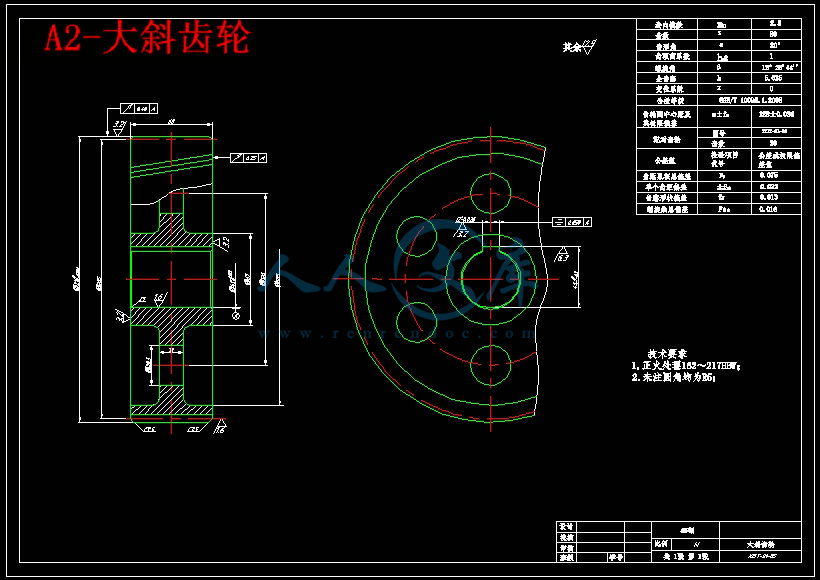
A2-大斜齿轮.dwg
A3-低速轴.dwg
A3-高速轴.dwg
A4-中间轴.dwg
A4-小斜齿轮.dwg
压缩包内文档预览:(预览前20页/共46页)
预览图 预览图 预览图 预览图 预览图 预览图 预览图 预览图 预览图 预览图 预览图 预览图 预览图 预览图 预览图 预览图 预览图 预览图 预览图 预览图
编号:10569839    类型:共享资源    大小:1.52MB    格式:ZIP    上传时间:2018-08-30 上传人:好资料QQ****51605 IP属地:江苏
50
积分
关 键 词:
20 自动 伸缩 设计 全套 cad 图纸 以及 毕业 答辩 论文
资源描述:

【温馨提示】 购买原稿文件请充值后自助下载。

以下预览截图到的都有源文件,图纸是CAD,文档是WORD,下载后即可获得。


预览截图请勿抄袭,原稿文件完整清晰,无水印,可编辑。

有疑问可以咨询QQ:414951605或1304139763

摘要

自动伸缩门是一款机电一体化的产品,它由控制系统实现电机的转动,再由电机通过一系列传动装置,带动门体运动。本文首先阐述了自动伸缩门产生的背景,它在当前社会中的发展状况,以及对它进行研究的意义。继而根据已知条件对相关参数进行计算,选择合适的电动机。然后设计减速器传动方式,确定传动方式之后再依次对实现传动的各个零件(包括齿轮、轴、传动链、链轮)的各个参数进一步计算,接着要对设计完的零件进行强度校核。最后,对自动伸缩门的控制系统进行了设计,本文采用单片机进行系统控制,从而实现电动机的正转、反转、停转,汉字显示方式控制,无线遥控控制等,再根据这些功能来选择实现这些功能所需要的硬件设备,然后将这些设备正确连接来完成硬件系统的设计。


关键词:  伸缩门;减速器;控制系统


Abstract

    Automatically retractable door is a product of mechatronics. Under the control of the system, it can make the motor rotate, and then, through a series of gearing, the motor drive the whole door to move. This paper first describes the background to generate automatic retractable door, its development in the current society, and the significance to study it. Then to calculate of the relevant parameters based on the known conditions and select the appropriate motor. Next, we should determine the way of transmission, after which the parameters of the various transmission parts need to be further calculated, including the design of gears, the design of shafts and the design of transmission chain and sprocket wheels. Afterwards, the intensity of each part will be checked. Finally, the control system of automatically retractable doors is designed. In this paper, we use single-chip to achieve system control, which can realize the normal-reverse transfer of the motor, the way of characters display, and wireless remote control. To implement these functions, we must choose necessary hardware devices, and these devices should be properly connected to complete the design of the hardware system.


Keywords   retractable door    reducer    control system


目       录

摘要 I

关键词: I

Abstract II

1 绪论 1

1.1 课题研究内容 1

1.2 自动伸缩门的背景、发展及研究意义 1

2 减速器的设计 3

2.1电动机的选择 3

2.2 传动比的计算及分配 4

2.3 计算传动装置的运动和动力参数 5

2.4齿轮设计 6

2.4.1高速级圆锥齿轮设计 6

2.4.2低速级斜齿圆柱齿轮设计 11

2.5轴的设计 18

2.5.1高速轴的设计与计算 18

2.5.3 中间轴的设计与计算 24

2.5.3 低速轴设计 30

3 链传动设计 37

4 控制器设计 39

4.1 总体设计 40

4.2 硬件选择 40

4.2.1 电机控制 40

4.2.2 遥控电路 40

4.2.3 汉字显示模块 41

4.3 硬件连接原理图 41

5 门体设计 43

5.1 总体设计 43

5.2 结构设计 44

结论 45

致谢 46

参考文献 47


1 绪论

1.1 课题研究内容

本课题研究的对象是自动伸缩门,它主要由机头、门体和行走轮组成,其中机头是其核心部分,内部包括电动机、控制系统、以及减速装置。工作时,由控制系统控制电动机的正转和反转,然后通过一系列的减速装置带动行走轮行走,从而实现伸缩门的前进与后退。

本课题的主要研究的是与本专业联系紧密的电动机和减速装置部分。首先根据原始参数选择合适的电动机,然后选择合适的传动机构。为实现门体的正常运动,本设计拟选用圆锥-圆柱齿轮传动,然后通过链传动带动行走轮行走。

1.2 自动伸缩门的背景、发展及研究意义

在20世纪,自动门在我国并不是很普遍,其核心技术也很落后,尤其是它内部的控制系统,当时在我国根本无法研制出来,因此很多都是从西方国家进口而来。但后来,随着科学技术的不断发展,我们自己也渐渐可以开发出自动伸缩门生产的整套流程。自动伸缩门从产生到投入使用已经有一段时间,它的兴起是在1996年,那段时间,很多厂家抓住这个契机大量生产,市面上的伸缩门的种类非常多,这样自然而然带来的就是伸缩门的质量问题,相当一部分该产品很不符合使用要求,存在着许多隐患。于是针对这个问题,国家于1997年颁发了通知,要求相关部门及研究院,修编一套自动伸缩门的规格,其目标是向国内外先进企业看齐。

此后随着人民生活水平的提高,市场需求的逐渐扩大,科技水平的日益发达,自动伸缩门的功能越来越强大,应用也越来越广泛。虽然在国内它的起步比较晚,但相对来说其发展还是比较迅速的。如今,自动门在日常生活中可以说是随处可见,学校、工厂、医院等各个企事业单位均使用自动伸缩门作为自己的门面,不仅方便了车辆的进出与管理,同事还节省了人力物力。

因此,对自动伸缩门进行研究对改善我们的日常生活,促进社会经济效益有着极其重要的意义。

1.3 文章结构

本文首先对本课题进行简单的介绍,并阐述自动伸缩门产生的背景,它在当前社会中的发展状况,以及对它进行研究的意义。

第二章主要对实现传动的减速器进行设计。包括电动机选型,传动比分配以及相关参数计算,还有传动零部件的设计。

第三章主要对链传动进行设计,它主要用来实现减速器输出轴到伸缩门滚轮之间的传动。

第四章主要对自动伸缩门的控制系统进行设计。主要通过单片机实现对电动机的正转、反转、停转,汉字显示方式以及无线遥控的控制,并作出硬件连接原理图。

最后主要进行了门体结构的设计,并总结本次设计过程,对设计中提供帮助的老师同学表示感谢。


内容简介:
外文翻译Artificial hip joint学 生 姓 名 班 级 学 院 名 称 专 业 名 称 指 导 教 师 11. IntroductionIt has been recognised by a good number of researchers that the computation of the pressure distribution and contact area of artificial hip joints during daily activities can play a key role in predicting prosthetic implant wear 1, 2, 3 and 4. The Hertzian contact theory has been considered to evaluate the contact parameters, namely the maximum contact pressure and contact area by using the finite element method 1 and 2. Mak and his co-workers 1 studied the contact mechanics in ceramic-on-ceramic (CoC) hip implants subjected to micro-separation and it was shown that contact stress increased due to edge loading and it was mainly dependent on the magnitude of cup-liner separation, the radial clearance and the cup inclination angle 3 and 4. In fact, Hertzian contact theory can captured slope and curvature trends associated with contact patch geometry subjected to the applied load to predict the contact dimensions accurately in edge-loaded ceramic-on-ceramic hips 5. Although the finite element analysis is a popular approach for investigating contact mechanics, discrete element technique has also been employed to predict contact pressure in hip joints 6. As computational instability can occur when the contact nodes move near the edges of the contact elements, a contact smoothing approach by applying Gregory patches was suggested 7. Moreover, the contributions of individual muscles and the effect of different gait patterns on hip contact forces are of interest, which can be determined by using optimisation techniques and inverse dynamic analyses 8 and 9. In addition, contact stress and local temperature at the contact region of dry-sliding couples during wear tests of CoC femoral heads can experimentally be assessed by applying fluorescence microprobe spectroscopy 10. The contact pressure distribution on the joint bearing surfaces can be used to determine the heat generated by friction and the volumetric wear of artificial hip joints 11 and 12. Artificial hip joint moment due to friction and the kinetics of hip implant components may cause prosthetic implant components to loosen, which is one of the main causes of failure of hip replacements. Knee and hip joints moment values during stair up and sit-to-stand motions can be evaluated computationally 13. The 2effect of both body-weight-support level and walking speed was investigated on mean peak internal joint moments at ankle, knee and hip 14. However, in-vivo study of the friction moments acting on the hip demands more research in order to assess whether those findings could be generalised was carried out 15.The hypothesis of the present study is that friction-induced vibration and stick/slip friction could affect maximum contact pressure and moment of artificial hip joints. This desideratum is achieved by developing a multibody dynamic model that is able to cope with the usual difficulties of available models due to the presence of muscles, tendons and ligaments, proposing a simple dynamic body diagram of hip implant. For this purpose, a cross section through the interface of ball, stem and lateral soft and stiff tissues is considered to provide the free body diagram of the hip joint. In this approach, the ball is moving, while the cup is considered to be stationary. Furthermore, the multibody dynamic motion of the ball is formulated, taking the friction-induced vibration and the contact forces developed during the interaction with cup surface. In this study, the model utilises available information of forces acting at the ball centre, as well as angular rotation of the ball as functions of time during a normal walking cycle. Since the rotation angle of the femoral head and their first and second derivatives are known, the equation of angular momentum could be solved to compute external joint moment acting at the ball centre. The nonlinear governing equations of motion are solved by employing the adaptive RungeKuttaFehlberg method, which allows for the discretisation of the time interval of interest. The influence of initial position of ball with respect to cup centre on both maximum contact pressure and the corresponding ball trajectory of hip implants during a normal walking cycle are investigated. Moreover, the effects of clearance size, initial conditions and friction on the system dynamic response are analysed and discussed throughout this work.2. Multibody dynamic model of the artificial hip jointThe multibody dynamic model originaly proposed by Askari et al. 16 has been considered here to address the problem of evaluating the contact pressure and moment of hip implants. A cross section A-A of a generic configuration of a hip joint is depicted in the diagram of in Fig. 1, which represents a total hip replacement. Fig. 1 also shows the head and cup placed inside of the pelvis and separated from stem and 3neck. The forces developed along the interface of the ball and stem are considered to act in such a way that leads to a reaction moment, M. This moment can be determined by satisfying the angular motion of the ball centre during a walking cycle. The available data reported by Bergmann et al. 17 is used to define the forces that act at the ball centre. This data was experimentally obtained by employing a force transducer located inside the hip neck of a live patient. The information provided deals with the angular rotation and forces developed at the hip joint. Thus, the necessary angular velocities and accelerations can be obtained by time differentiating the angular rotation. Besides the 3D nature of the global motion of the hip joint, in the present work a simple 2D approach is presented, which takes into account the most significant hip action, i.e. the flexion-extension motion. With regard to Fig. 2 the translational and rotational equation of motion of the head, for both free flight mode and contact mode, can be written by employing the NewtonEulers equations 18 and 19, yieldingequation(1)MOk=I k,MO=Mk (Rj)nFPjt0Mk0equation(2)FX=mx, FX=fx+(FPjt+FPjn)i0fx0equation(3)4FY=my, FY=fy+(FPjn+FPjt)jmg0fy 0where FPjn and FPjt denote the normal and tangential contact forces developed during the contact between the ball and cup, as it is represented in the diagram of Fig. 3. In Eqs. (1), (2) and (3), x, y and are the generalised coordinates used to define the systems configuration. In turn, variable m and I are the mass and moment of inertia of ball, respectively. The external generalised forces are denoted by fx, fy and M and they act at the centre of the ball as it is shown in Fig. 3. The gravitational acceleration is represented by parameter g, Rj is the ball radius and represents relative penetration depth between the ball and cup surfaces.Fig. 1. A schematic of the artificial hip implant with the cross section A-A (Left figure), and the head and cup separated from the neck and stem through the cross section A-A (Right figure).Figure options Download full-size imageDownload high-quality image (142 K)Download as PowerPoint slideFig. 2. A schematic of the head and cup interaction observed in the Sagittal plane.Figure options6 Download full-size imageDownload high-quality image (87 K)Download as PowerPoint slideFig. 3. Free body diagram of ball and corresponding external, internal and body forces and moment.Figure options Download full-size imageDownload high-quality image (87 K)Download as PowerPoint slideTheDownload as PowerPoint slideThe penetration depth can be expressed as 20equation(4)=r(RbRj)=r(Rb Rj)in which Rb denotes the cup radius and (RbRj) represents the joint radial clearance, which is a parameter specified by user.In the present study, the cup is assumed to be stationary, while the head describes the global motion. With regard to Fig. 2, it can be observed that Oj and Ob denote the head and cup centres, respectively. While Pj and Pb represent the contact points on the head and cup, respectively. The magnitude and orientation of the clearance vector are denoted by r and , respectively. In general, r and can be expressed as 7functions of the generalised coordinates used to describe the configuration of multibody mechanical system. The normal and tangential unit vectors at the contact point can be written asequation(5)n=cosi+sinjequation(6)t=sini+cos jIn order to compute the normal contact and tangential forces, it is first necessary to evaluate the relative tangential and normal velocities at the contact points, which can be obtained as follows: 17equation(7)vpj/pb=n+(r+Rjj)t=vnn+vttwhere vnvn and vtvt are module of the normal and tangential velocities, respectively. Thus, Eqs. (2) and (3) can be re-written as follows:equation(8)m00mxy=FXFY8Using now the concept of the state space representation, the second order equations of motion (8), can be expressed as a first order equation set asequation(9)=H(z)where z=z1z2z3z4=xy and H(z)H(z) is expressed as follows:equation(10)=1234=z3z4FX(z) FY(z)It must be mentioned that the r, and their time derivatives can be obtained with respect to state space parameters as follows:equation(11)=atan(z2z1)equation(12)r=z12+z22equation(13)= z2z3+z1z4z12+z22z12equation(14)=z1z3+z2z4z12+z22It is known that the evaluation of the contact forces developed during an impact event plays a crucial role in the dynamic analysis of mechanical systems 21, 22 and 23. The contact forces must be computed by using a suitable constitutive law that takes into account material properties of the contacting bodies, the geometric characteristics of impacting surfaces and impact velocity. Additionally, the numerical approach for the calculation of the contact forces should be stable in order to allow for the integration of the mechanical systems equations of motion 24. Different constitutive laws are suggested in the literature, being one of the more prominent proposed by Hertz 25. However, this law is purely elastic in nature and cannot explain the energy loss during the impact process. Thus, Lankarani and Nikravesh 26 overcame this difficulty by separating the contact force into elastic and dissipative components asequation(15)Fpjn=(Kn+D )n10Regarding Lankarani and Nikravesh model, normal contact force on the head is expressed asequation(16)Fpjn=K3/2(1+3(1ce2)4()nwhere and () are the relative penetration velocity and the initial impact velocity, respectively, and ce is the coefficient of restitution. The generalised stiffness parameter K depends on the geometry and physical properties of the contacting surfaces, which for two internal spherical contacting bodies with radii Ri and Rj can be expressed as 25equation(17)K=43(i+j)(RiRjRi Rj)2in which the material properties ii and jj are given byequation(18)z=1 z2Ez11At this stage, it must be said the use of Eq. (15) is limited by Loves criterion, that is, it is only valid for impact velocities lower than the propagation velocity of elastic waves across the solids 27.It is known that the way in which the friction phenomena are modelled, plays a key role in the systems behaviour 28. In the present study, the tangential friction force are evaluated by using a modified Coulomb friction law, which can be expressed as 29 and 30equation(19)Fpjt=(vt)|Fpjn|vt|vt|tThe friction force is described in the sense of Coulombs approach, and is proportional to the magnitude of the normal force developed at the contact points, where the ratio is the coefficient of friction, , which is dependent on the relative tangential velocity. The model considered in reference 17 is employed here for the purpose of evaluating the coefficient of friction, which can be written asequation(20)(vt)=(cfv02(|vt|v0)2+cf)sgn(vt),|vt|Fig. 4. Stribeck characteristic for dry friction.Figure options Download full-size imageDownload high-quality image (102 K)Download as PowerPoint slideNormal and tangential forces described above are present if the system isin contact situation, which means detecting impact or contact is one important step. Moreover, to compute the contact force, the initial impact velocity has to be calculated as an initial condition for following regimes, which could be in contact or in free flight, the following condition should be checked during the solution process by progressing time. Therefore, a contact event is detected when the following condition is verifiedequation(21)(ti)0Indeed, the precise instant in which the phase changes from free flight to contact is of paramount important instant because initial conditions for the next dynamic scenario are provided from exactly this instant 31.3. Computing quasi-static and dynamic maximum contact pressuresFor the CoC hip implants used nowadays, with 5, 3 and 2 mm thick ceramic insert, it has been demonstrated that the radius of the contact area between the femoral head and the acetabular cup is relatively small compared with that of the femoral head and the ceramic insert thickness. Therefore, the Hertzian contact theory can be utilised to estimate the contact parameters such as the maximum contact pressure and the contact area 1. Hertzian contact theory can also be considered to evaluate contact pressures in CoC hip arthroplasty even though the ball is in contact with the cup as edge loading in CoC hip arthroplasty 5. When the system is in edge-loading, the contact area is no longer circle but ellipse 4 and 5. In the present study, contact pressure and contact area are determined using two different approaches, namely quasi-statics and dynamics.Assuming that the cup and head held in contact by a force F, as it is shown in Fig. 5, such that their point of contact expands into a circular area of radius a, 32equation(22)a=KaF3whereequation(23)Ka=(34(112/E1)+(1 22/E2)(1/Rj 1/Rb)1/314in which 1 1, E1E1 and 22, E2E2 are Poissons ratios and elastic modulii for the ball and cup, respectively. The maximum contact pressure occurs at the centre point of the contact area and can be calculated asequation(24)Pmax=3F2a2Fig. 5. Head and cup held in contact by a force F.Figure options Download full-size imageDownload high-quality image (73 K)Download as PowerPoint slideThe15The local coordinate system (XYZ) is located at the centre point of the contact area as it is illustrated in Fig. 1. Since the coordinate system is defined as a local system, the tangential stresses can expressed as 32equation(25)XZ=(vt)vt|vt|limY0Y=Pmax (vt)vt|vt|For an element close to the contact point, when Y approaches zero, the principal stresses are written asequation(26)1=Pmax,2= Pmax(+0.5+(vt) 3=Pmax(+0.5(t)If (+(vt)0.5( + (vt)0.5 so that max= Pmax(+0.5+ (vt)max= Pmax(+0.5+(vt) if (+ (vt)0.5(+(vt)0.5 so that max= Pmaxmax=Pmax.Normal contact force, Eq. (16), is calculated as a function of time, solving resultant equations of multibody dynamic system. This normal contact force is substituted into Eqs. (22) and (24) to determine contact pressure distribution and contact area in ceramic-on-ceramic hip implants dynamically. To acquire quasi-static results, external normal contact loads (F) based on ISO14242-1 testing standard are introduced into Eqs. (22) and (24). These two approaches allows for the comparison between dynamic and quasi-static situations. Therefore, it is convenient to define a parameter, dif., that conveys the difference between quasi-static and dynamic results of maximum contact pressures. Projection of the governing motion equations, Eq. (8), on the normal direction vector n provides the ball motion equation in normal direction asequation(27)16m=fxcos +(fymg)sinFPjn=fext,nfcont,nwhere denotes the indentation acceleration. Substituting contact area from Eq. (22), normal contact force computed from Eq. (15) and normal contact force from ISO 14242-1 testing standard into Eq. (24), then, the difference between the cube of maximum contact pressures computed from quasi-static analysis and dynamic analysis can be evaluated as follows:equation(28)dif.=max,qs3max,d3=2783ka6m The angular acceleration of femoral head can be calculated as the derivative of the ball angular velocity during a normal walking cycle. An external moment, M, which acts on the ball centre is required to cause hip implant to rotate with the known angular acceleration during a corresponding activity cycle. Therefore, the angular momentum, Eq. (1), has to be solved to obtain the external moment as follows:equation(29)Mk=Ik+(Rj)nFPjt0Ik0174. Description of numerical model utilisedIt is known that the resultant equations of multibody dynamic models for hip implants, Eq. (9), are nonlinear and must be solved by using numerical method. Thus, in the present work, an adaptive RungeKuttaFehlberg method is considered to discretise the interval of time of analysis. An error threshold is defined. The error magnitude is calculated by comparing results obtained from explicit method with different orders. If the error magnitude is greater than the error threshold, the time step, h, must be halved and computation is done again in order to acquire accurate and stable outcomes. In the present study, the angular velocity around the flexion/extension direction z, j, together with the force in the vertical direction, fy, are considered. Vertical load and angular velocity are illustrated according to ISO14242-1 in Fig. 6 and Fig. 7, respectively. The geometrical and material properties of the head and cup are listed in Table 1. Moreover, integration step sizes for free flight and contact modes are assumed to be 0.00001 s and 0.0000001 s, respectively, being the corresponding integration tolerances 0.000001 and 0.00000001.Fig. 6. The vertical load during a normal walking cycle based on ISO14242-1 testing standard 33 and 3
温馨提示:
1: 本站所有资源如无特殊说明,都需要本地电脑安装OFFICE2007和PDF阅读器。图纸软件为CAD,CAXA,PROE,UG,SolidWorks等.压缩文件请下载最新的WinRAR软件解压。
2: 本站的文档不包含任何第三方提供的附件图纸等,如果需要附件,请联系上传者。文件的所有权益归上传用户所有。
3.本站RAR压缩包中若带图纸,网页内容里面会有图纸预览,若没有图纸预览就没有图纸。
4. 未经权益所有人同意不得将文件中的内容挪作商业或盈利用途。
5. 人人文库网仅提供信息存储空间,仅对用户上传内容的表现方式做保护处理,对用户上传分享的文档内容本身不做任何修改或编辑,并不能对任何下载内容负责。
6. 下载文件中如有侵权或不适当内容,请与我们联系,我们立即纠正。
7. 本站不保证下载资源的准确性、安全性和完整性, 同时也不承担用户因使用这些下载资源对自己和他人造成任何形式的伤害或损失。
提示  人人文库网所有资源均是用户自行上传分享,仅供网友学习交流,未经上传用户书面授权,请勿作他用。
关于本文
本文标题:20米自动伸缩门设计【全套CAD图纸和毕业答辩论文】
链接地址:https://www.renrendoc.com/p-10569839.html

官方联系方式

2:不支持迅雷下载,请使用浏览器下载   
3:不支持QQ浏览器下载,请用其他浏览器   
4:下载后的文档和图纸-无水印   
5:文档经过压缩,下载后原文更清晰   
关于我们 - 网站声明 - 网站地图 - 资源地图 - 友情链接 - 网站客服 - 联系我们

网站客服QQ:2881952447     

copyright@ 2020-2025  renrendoc.com 人人文库版权所有   联系电话:400-852-1180

备案号:蜀ICP备2022000484号-2       经营许可证: 川B2-20220663       公网安备川公网安备: 51019002004831号

本站为文档C2C交易模式,即用户上传的文档直接被用户下载,本站只是中间服务平台,本站所有文档下载所得的收益归上传人(含作者)所有。人人文库网仅提供信息存储空间,仅对用户上传内容的表现方式做保护处理,对上载内容本身不做任何修改或编辑。若文档所含内容侵犯了您的版权或隐私,请立即通知人人文库网,我们立即给予删除!