肥皂盒上盖的注塑模设计(全套含CAD图纸、三维图纸)
收藏
资源目录

压缩包内文档预览:
编号:12793381
类型:共享资源
大小:45.38MB
格式:ZIP
上传时间:2019-01-06
上传人:机****料
认证信息
个人认证
高**(实名认证)
河南
IP属地:河南
50
积分
- 关 键 词:
-
肥皂盒
注塑
设计
全套
cad
图纸
三维
- 资源描述:
-


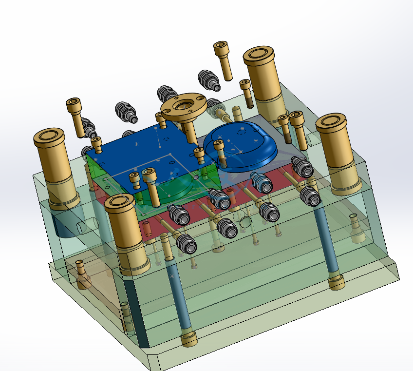


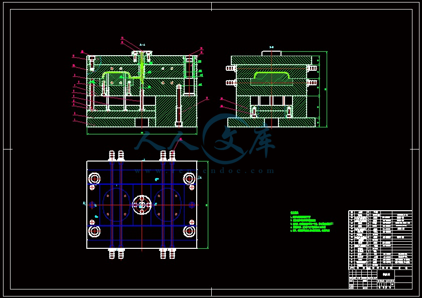


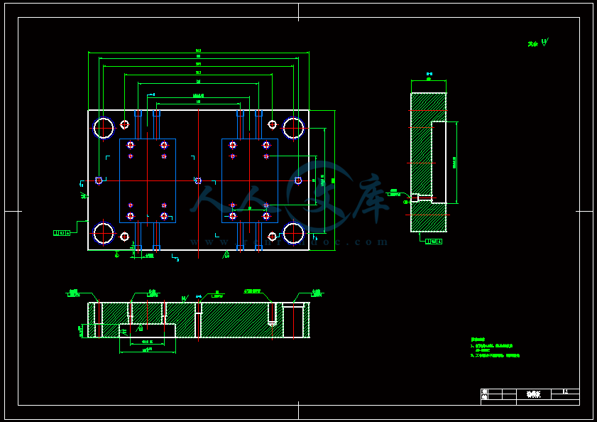
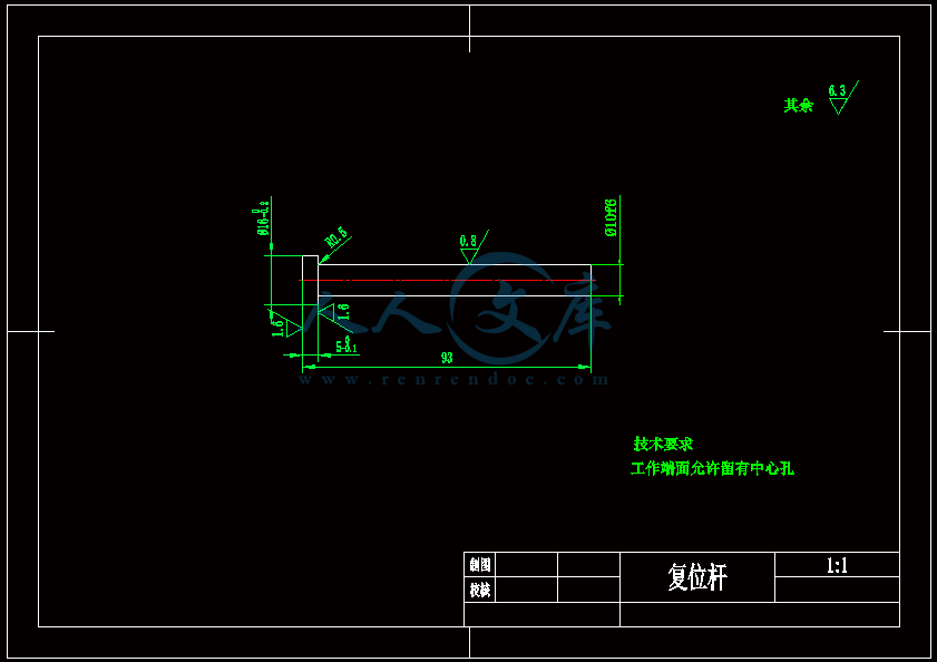


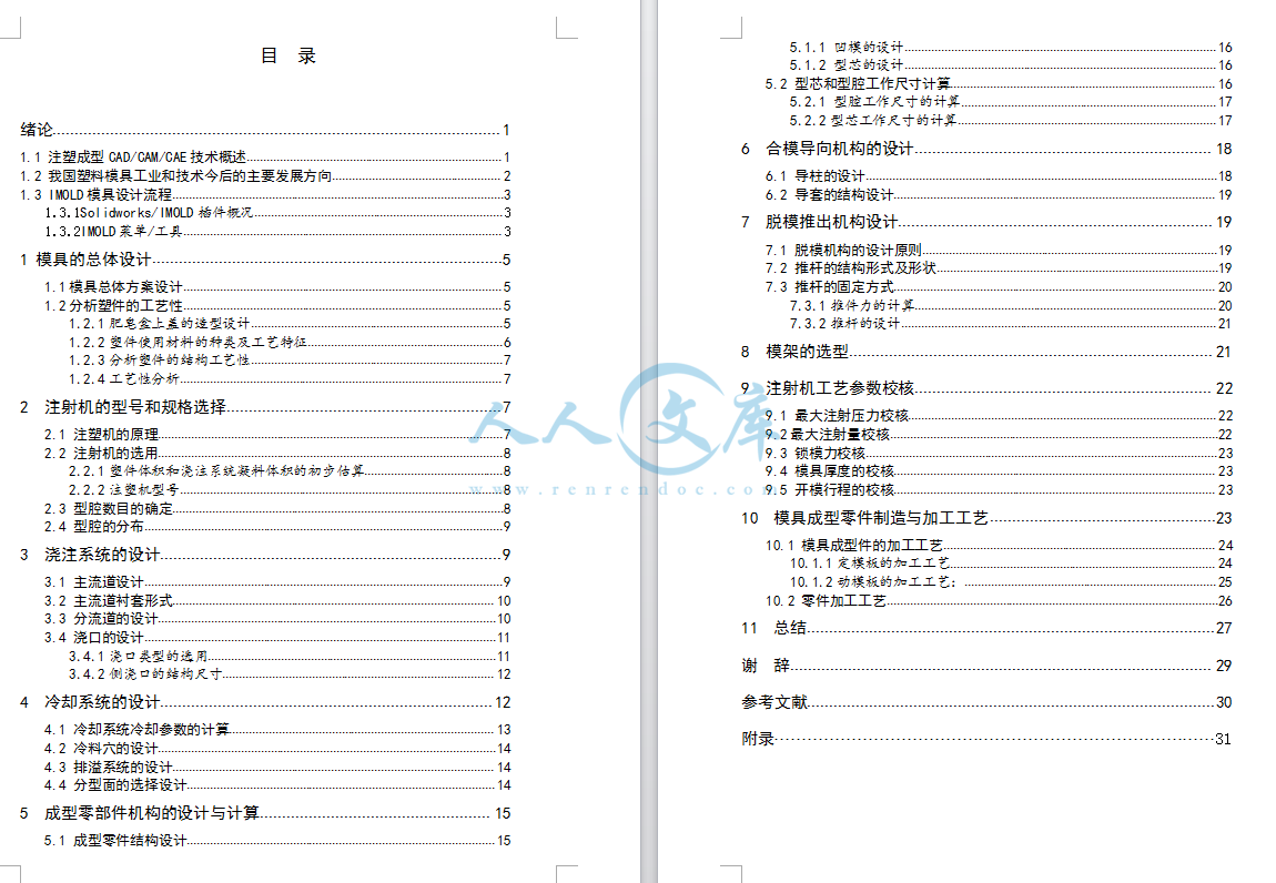


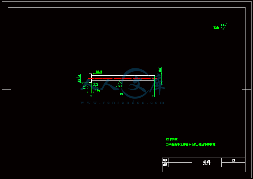


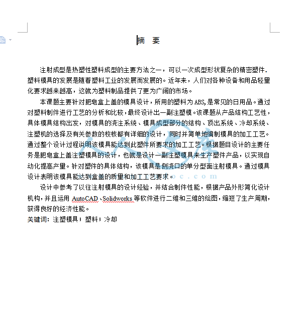
- 内容简介:
-
在不规则塑料平板进行注塑模具冷却水道的设计 Zone-Ching Lin and Ming-Ho Chou,机械工程学系,国立台湾科技大学,台北,台湾,中华民国。摘要 关于复杂的变量和参数在异形塑料平板注塑模具冷却通道设计的调查显示,向量和简单的数学计算被用来解决有关冷却的问题造成不同部署的模具制品尺寸。此外,基本的几何特征表面符号和数据库成立。接下来,在一个长方形的塑料平板的基础上,用基本几何特征面来撰写和提交成型的模具产品。同等面积的转换概念应用到了含有温和的改变形状的异形塑料平板冷血渠道模型和部署的选择中。在能量平衡的基础上第一阶段优化冷却时间。使用一个简洁的公式与经验作为约束优化算法的设计,以找出最佳的冷却时间和所需的最佳几何因素的制约。然后优化派生通道部署,以达到快速、均匀冷却模具的要求。本文提出的方法通过转换为等效矩形区域能够处理异形的塑料平板产品。这种方法简化了热源分布不均匀造成的成型产品的渠道部署问题和降低的试验和错误的实例。此外,提出的系统架构方法能够完成优化速度比传统的有限差分法快,从而节省了冷却通道设计所花费的时间,实现了快速和均匀冷却成品。关键词:注塑模具,能量平衡,优化设计介绍 一个最佳的冷却系统设计和冷却过程中操作条件是注塑成型过程的关键(罗萨托罗萨托1985),因为这一进程都影响着成型产品的质量和生产率。高效冷却系统的设计可以减少所需的冷却时间。均匀冷却可提高模具产品收缩、热残余应力和翘曲等缺陷。因此最佳的冷却系统设计必须能同时达到尽可能短的冷却时间和均匀冷却的目标。在注塑过程中有这么一个参数,这个影响了模具产品的均匀冷却的重要因素是冷却系统的渠道部署。一个设计良好的散热通道部署,再加上适当的操作条件,可以实现快速和均匀冷却的目标,以至于缩短流程周期,提高模具产品的质量。 在80年代初期,研究的注意力转向了冷却系统和模腔的热的相互作用。在此期间,大多模拟程序处理的只有一维或者二维的平均稳态分析或者周期的准稳态分析(奥斯汀1985年)。使用的方法包括有限差分法,有限元方法,周期的平均边界元法(1987年,辛格,辛格王1982年,巴罗和防漏1981,1982)。在1985年后公布的一般分析研究步骤已经通过了所谓的两阶段或三阶段分析(权,沉,王1986)出版。初步的分析主要用于形状因素方法来评估冷却系统的效率(权1986年沉,王,陈,胡。 大卫杜夫1990年)。这一次的分析结果在冷却系统的运行状况和冷却通道的位置和大小的基础上已经得到控制。分析方法是所有的一维或二维稳态分析或准稳态(权,沉,王1986;陈,胡锦涛1990年,大卫杜夫;Himasekhar,王1989年,Lottey;himasekar? hiber1989年,王,陈和胡1991)。一些成品的仿真分析软件包在1990年后变得有价值(Himasekar1989;Himasekhar和王199(I),其中包括MCAP,MOLDCOOL,MOLDTEMP,POLYCOOL2和-COOL3D。分析方法包括有限差分法,有限元法,边界元法(199 Turng和王; Himasekhar,Lottey1992年,王)。有时使用的有限元方法和形状因子的方法相结合(Glavill和丹顿1977)。这些分析程序的开发减少了存储空间和CPU的内部运行时间,试图产生与现实条件相匹配的分析结果(Himasekhar,lottey,王1992)。本文结合能量平衡和经验算法来构建系统模块。它还使用载体和简洁的数学计算来处理这样一个复杂的系统,并能摆脱复杂的数值计算和分析。 按照惯例,模具设计依赖于经验和无数次试验和错误后的直觉,因此,它常常导致性能和经济的负担。如今,得益于电脑的快速发展,模具可以用理论和数值来设计,其结果可以预测或者通过Moldflow的包装软件直接模拟,从而提高成本效益和产品质量。其中,在这么多的数值计算方法中,有限元方法比有限差分具有更好的稳定性和收敛性。但它要有更复杂的理论和需要更大的计算机内存空间。虽然包装行业所使用的软件能迅速解决模具设计的问题,但它不能有效地帮助工程师简化该系统的复杂性和模糊性。此外,用于模拟的包装软件,事实上只能解决设计中遇到的60%70%的问题。试验和错误是不可避免的,缺乏经验的工程师在设计中仍然成为一个有影响力的变量。 使用长方形的塑料平板作为研究的主体,本文简化了在冷却通道模具设计中遇到的设计变量和有影响力的参数,帮助设计工程师完成快速冷却最佳流程和方案的写作,并获得最佳的冷却时间和冷却通道部署。这种观念被采用到简化注塑模具冷却通道部署中。本研究结合简洁的能量平衡算法、形状因素和经验来构造模块化关系,以作为冷却通道部署优化设计的参考模板。注塑模具中冷却系统的理论 模具冷却系统通常包含一个温度控制机、泵、冷却液供应歧管、软管和集水歧管。在这些模块中,温度控制系统影响模具的温度和稳定度的均匀分布。提高了冷却效率,可以提高其生产效率。注塑模具的冷却 在注塑模具中,冷却时间通常占剧整个周期的70%80%。图一显示了模具的冷却时间和成型周期的关系(周1999)。一个有效的冷却循环设计,缩短了冷却时间,有效地提高了生产效率,降低了成本。此外,均匀冷却防止了产品由于热应力造成收缩、翘曲、变形等缺陷,然后增加成型产品的尺寸精度和可靠性,同时对产品的质量也有所改善。图二显示了有效冷却,模塑制品的质量和批量生产之间存在的关系(周1999)。一般情况下,一副模具由模体、冷却通道和塑料材质这三个部分组成。图三显示了一个简化的模具冷却机制。本文中,做这样一个冷却假设分析,热能在没有丧失的情况下通过塑料制品的边缘,也就是说,冷(热传导)只发生在厚度方向。图四显示了一般模具的导热系数,它还假设了热能全部被冷却液直接带走,即热能只由塑料材质转移,不包括模具外部因辐射、对流和热传导转移的5%的能量。因此导热路径可以简化如下:热能从熔融的塑料材质通过热传导转移到熔融塑料材质和模具的接口。热能通过这个接口,到达模体,接着通过热传导到达模具和冷却液表面,其次,在接口处对流传到冷却液,最后热能全部被冷却液带走。 注塑模具冷却水道设计的注意事项 注塑模具通常用于大批量生产中,最重要值得关注的是怎样提高产量,达到更好的经济效益。最直接和有效的方法是缩短冷却时间,从而实现产品的快速冷却。同时,确保产品温度的均匀和质量的维持。保持均匀冷却的方式也是一项基本要求,对于模具冷却而言,模具设计工程师需要确定下列设计参数:冷却通道的位置、冷却通道的尺寸、冷却通道的形式、冷却通道的部署和连接、冷却通道循环的长度以及冷却剂的流速。需要注意的是冷却通道必须使用标准的尺寸,可以使用工具和标准规范的连接件快速换模。快速和均匀冷却是模具设计的主要指导方针。因为冷却过程占据整个成型周期的70%80%,如果冷却系统可以快速地将产品降温,即对冷却时间进行小的改进,可以大大缩短整个成型时间和提高产量。因此缩短冷却时间的方法对设计师是至关重要的,这也是本文讨论的主题。如果在注塑过程中出现不均匀冷却情况,它们产生的热压力将造成收缩和翘曲。所以有必要保持模具制品的均匀冷却,从而减少产品遭受热应力和随后的收缩和翘曲。换句话说,成型产品两面的温差应该小以达到模具统一的温度。凭经验,温差不能超过十度。最简单和最有效的方法是匹配冷却通道和成型产品的热传导区域,这是本文保持产品均匀冷却的基础(扬和秦1990)。注塑模具冷却水道的简明计算理论 注塑成型过程中的每个阶段包含一个冷却的过程。因此冷却时间一般有如下解释:“熔融塑料一旦被注入到型腔,就开始降温,在注入阶段持续冷却,填充后,冷却贯穿整个成型周期,直到塑造产品足够硬不能排出型腔,这被认为是冷却时间结束。”正如图一所示,冷却时间为t,约占整个成型周期的70%80%。因此,缩短冷却时间t到数个百分点,对整个成型效果有巨大影响。在本文中,最佳的冷却时间被作为注塑模具冷却系统的冷却水道设计的基础。注塑模具冷却水道设计的基本假设 注塑模具的设计目标是尽量减少冷却时间,有许多影响冷却时间的因素。在这里,图五简要地列出了与冷却时间有关的因素作为设计考虑的基础。这些因素如下所述(张1985): 1. 成型产品的厚度H。越厚的成型产品,需要的冷却时间越长。2. 成型产品的形状。如果成型产品的形状很复杂,那么它的成型效果在一些区域就不会表现得太明显,这可能反过来影响整个成型件的冷却时间。3. 塑性材料的熔体质量。因为不同的塑料有不用的热扩散,其导热效果也不同。塑性材料有更大的热扩散和导热率,需要更短的冷却时间。4. 注塑温度和弹射温度。注塑温度越高,所需的冷却时间也越长。相比之下,弹射时间越短,所需的冷却时间越长。5. 模具材料。因为不同金属材料的模具有不一样的导热性,其导热效果也不同。金属具有更大的热传导性,需要更短的冷却时间。6. 冷却通道的数量、位置和大小。冷却通道的设计对整个冷却时间有决定性的影响。一般来说,冷却通道的数量越多,成型产品越接近冷却通道或者通道的直径越大,冷却效果越好,冷却时间越短。7. 冷却液的质量。不同的冷却液有不同的热传导系数、比热、密度和粘度。因此,有不同的传热效果。8. 冷却液的流量和温度。冷却液的流量必须达到湍流,以增加传热效果。此外,冷却液温度越低,冷却时间越短。 冷却阶段涉及非常复杂的问题。为了简化这一过程,该研究提出以下一些假设:1. 由于模具材料物理性能的改变导致温度和压力不显著,所以它们被认作常数。2. 假设塑料材质释放的能量全部被冷却液和模具材料吸收。3. 假设模具表面和冷却通道壁的温度是常数。4. 假设在初始阶段,模具和塑料材质有它们各自的均匀温度,且塑料不含任何固体的部分。5. 假设模具型腔内部的压力为常数。因此,边界层压力减小的影响被忽略,并且在凝固过程中,塑性材料的体积维持不变。6. 凝固潜热作为比热计算的一部分,而不开考虑边界层的位置。7. 假设塑料在整个冷却过程中处于静止状态,因此,从流动的热效应就忽略了。8. 在这项研究中,来自结晶过程的热效应也忽略。冷却时间的计算 模具内液态塑料冷却时间的计算一度被认为由鲍尔曼和舒曼研究。很多研究人员已经发表关于这个问题的研究(孙克宁和卡迈勒1970)。本文提出一种简明计算冷却时间的方法。在这里,模具内塑材的冷却和凝固问题用一个3-D瞬态热传导方程表示如下:式中表示塑料的热容k:塑料的导热系数:塑料的密度 X1,X2,和X3表示成型产品的热传导方向,其中X3表示厚度方向。塑材的结晶效率在这不考虑塑材的潜热此外,在大多数情况下,冷却主要发生在沿厚度的方向(X方向)。在注塑过程中,大多数能量在冷却过程中被带走。因此在短期填充的时间可以忽略,并假定塑材从统一的温度冷却,因此可以得出以下简明方程: 其中表示塑料的热扩散率在图六给出了边界条件,冷却时间关系式(3)和(4)可以由第一项的傅里叶方程得到。1. 冷却时间需从均匀温度降到T,成型产品在厚度方向的温度为: 2.如果从产品的厚度方向冷却到T,则可得到的冷却时间为: 其中:指冷却时间(秒) 指塑材的初始温度(度) 指注塑温度,即成型产品在厚度方向的平均温度()度 指成型产品的平均厚度(厘米) 3.传导形状因子:图七标有长度尺寸或者无量纲(年罗斯淄和哈奈特1973)。 其中d 指冷却直径 D 指冷却通道和熔融材质中心之间的距离 P 指两个冷却通道之间的距离 能量平衡原理 本文中的方程式3符合能量平衡原理,被用作冷却过程中的数学理论。冷却时间的解决方案是利用产品在厚度方向的平均温度降到T为基础,模具各部位的温度和热能如图四所示,作为热能传导的一般路径。q1 :单位时间内由塑材传到模具型腔的平均热量。 (6)q2 :从型腔表面传到冷却通道壁的热能。 (7)q3 :从冷却通道表面传到冷却液的热能。 (8)q4 :冷却液带走的热能。 (9) 其中 :模具型腔的平均温度 :熔融材质的初始温度 :成型产品的温度 :冷却液入口温度 :冷却液出口温度 :冷却通道壁温度 :平均水温 : 塑料的重量 :冷却液流速 :冷却液密度 :冷却通道长度 :冷却通道直径 :传导形状因子 冷却水道的位置和尺寸 冷却液通道的位置和形状可以造成复杂的模具形状。大多数情况下,钻床是用来钻孔的,然后用镗床进行精加工。确定冷却系统的尺度不是一项简单的任务。至于传热的问题,可以用电脑处理一部分。然而寻求解决的方法仍然存在困难,因为有各种边界条件。鉴于此,上述段落在简明热传导理论的基础上,对冷却通道的位置和尺寸进行介绍,在行业中用到的经验算法作为设计的基础,以获得更高的冷却效率。研究中冷却通道的直径和位置的经验算法如下: 1. 冷却通道的直径(d):冷却通道的直径必须能通过足够的冷却液,以产生湍流。一般来说,冷却通道直径的大小取决于成型产品的平均厚度。给出成型产品的厚度H和冷却通道的直径d,则经验算法如下: H2 mm 8 mm10 mm H4 mm 10 mm 12 mm H6 mm 10 mm 14 mm通常设定,以获得湍流和更高的冷却效率。 2. 冷却通道的位置:一般情况下,为获得更高的冷却效率,冷却孔应该尽量接近产品模具型腔表面,冷却孔之间的距离应保持一个最小值,如图七所示。冷却通道位置的经验算法如下:(1)冷却通道的间距(P):最好是冷却通道和模具型腔表面形成的三角形覆盖模具型腔表面,如图七所示。3d和5d是通常推荐用的间距值。(2)软管和产品的间距(D):一般情况,冷却通道与产品表面越近,散热效果越好。然而,如果D16 mm,越易发生温度的显著变化,因此,D的值通常取1.5d和3d。(3)冷却通道的长度(L)和(N):一般而言,这些变量的布置是在几乎有相同有效长度()冷却通道的表面和产品有相同传热区域()的基础上确定的,即0(杨和秦1990)。异形塑料平板上冷却水道的部署 一个理想的冷却系统,不仅要满足经济的划算(冷却时间短),还要能实现产品的统一和完全冷却。冷却质量的好坏,取决于冷却通道的设计。一般而言,为获得好的效果,设计是在冷却液能带走产品产生的所有热量的基础上进行的。冷却液带走的热量为,熔融塑料带给模具的热量为,则(杨和秦1990)。 如果冷却通道表面表示“冷却面”,产品表面或模具型腔表示“暖面”,则这两个面的热流发生在这表面上。不考虑压降的因素,将方程式10的经验算法用作设计的条件之一,能在产品给定的任何位置都保持均匀的温度。 (10) 其中:模具和冷却通道之间距离带来的温度变化。 :冷却液流动产生的温度变化。 :总的温度变化。 根据一般经验,当冷却通道总面积与产品散发热量区域的总面积相等,可以得到一个简单和最佳的布局。所以大于或者等于,如下: (11)其中 :产品散热的总面积。 :冷却通道总面积。 (12)d:冷却通道直径 L:冷却通道总长度因此总的冷却通道长度 (13) 一般而言,塑料制件的厚度相对于其形状是非常小的。假定热量的传导仅在厚度方向。因此,要计算产品散热的总面积,首先得建立其基本的外形特征(表面特征)。设计师可以继续进行等效矩形的转换,然后根据产品的形状确定其长度。接下来,在能量平衡原理基础上进行基本的数学计算,并结合表面特征得出散热的总面积。最后可以由式(13)获得相应的冷却通道长度。表面的基本形态特征 本文中,利用向量积和简单的数学公式推导所有基本特征表面的面积。把这些基本特征面相结合获得成型产品的散热面积。下面各节描述了基本特征的表面面积计算。 1. 形状:三角形 特征符号:A 其中 如果和,则它形成正三角形。如果 和,则它形成直角三角形。如果,则它形成等角三角形。2. 形状:平行四边形 特征符号:B 其中 如果或和或,则为平行四边形。 如果或和或,则为正方形。 如果,则为长方形。4. 形状:n边形(n5且n为整数) 特征符号:D 5. 形状:圆 特征符号:E , 则为圆,d为直径。 如果,则为椭圆。特征曲面的组合 本文对产品形状的研究主要是轻微的形变,而不是剧烈的变化,产品中更剧烈的变化在研究范围之外。一个简单的平面由一些基本的几何图形组成,本文用这个例子来解释特征曲面的结合。表一列出了产品的特征,形状如图八。在这些结构上,表一列出的基本特征面的所有区域派生成一个数据库。接着,特征面的相关性在建立的数据库基础上很清楚地描述出来,它们的树状结构如图九所示。然后,通过简单的数学组合方法,就可以推断出模塑制品的热扩散区。 表一 图八 非矩形塑料平板等效矩形的转换 如果成型产品在同一平面上,并且它的形变属于轻微变化,它必须考虑到其形状由一些简单的三角形、梯形和圆基本特征构成。相对于产品形状的其中一个因数来说,一个对称的矩形在同一个能达到最均匀的热传导。在这篇文章中,把一个矩形用作基本的表面特征去实现通道的部署。至于非矩形的产品形状,用一个等效矩形来替换。如图十所示的非矩形塑料平板,而图十一显示了图十非矩形塑料平板各个区域的等效矩形。执行步骤 用三个区域来解释等效矩形面积的导出。首先,把成型产品分成三个区域,所有区域都是在考虑均匀形变的基础上。第二,用一个图特征值作为等效矩形宽度的标准值,作为长度标准值。最后,等效长度作为通道部署的基础,以获得满意的冷却效果。的值是在各个宽度的最大值的讨论中确定的。执行的步骤如下:步骤一:从图十和图十一计算热传导面积和等效面积。 其中 是各个基本表面特征产生热量的面积。 是各个等效矩形的面积。步骤二:确定各个区域矩形特征的标准宽度。 其中是宽度的最大值。步骤三:计算各个区域的等效长度。 其中, 。步骤四:确定各个通道比例系数的分配。 步骤五:从优化方案中获取最佳冷去时间和设计所需的变量。步骤六:为几何形状因数连接到优化搜索程序,通过对话窗口找到最佳的通道位置P和D。 步骤七:计算各个区域所需的冷却通道长度。 总的冷却长度L:其中 步骤八:计算各区域冷却通道分配的数量。 实际上,冷却通道的数量应是一个常数,所以因此高斯原理是用来处理非整数部分,纠正一些冷却通道方法如下:各区域冷却通道的数量: 如果 ,如果这里,代表高斯。冷却通道的实际总数: 步骤九:纠正实际冷却通道的长度。 步骤十:在实际的冷却通道部署中,如果因为成型产品的几何尺寸导致空间而不能满足冷却通道的工作的数量,这结果必须根据经验和能量平衡原理来纠正。(1) 冷却通道的位置调整:冷却通道中心位置调整后可以覆盖整个热型腔表面,这里的tan-1 P和D分别代表冷却通道的间距和冷却通道和模具型腔的距离。(2) 冷却液流量的调整: 其中 q是总流量,是原始设计时的冷却通道总的横截面积,是冷却通道总的工作横截面积。不规则塑料平板注塑模具冷却水道的优化模型 为了简化,本文介绍一个复杂的冷去系统去简化注塑模具中冷却通道部署遇到的问题,系统的结构分为第一阶段冷却时间的优化和第二阶段结合因素和冷却通道部署的优化。第一阶段冷却时间的优化是基于能量平衡基础上进行的。然后使用一个简明的公式和经验算法作为优化设计的约束,以获得最佳的冷却时间和最佳限制的导热形状因子。冷却通道位置部署的导出是在最佳导热形状因子和位置部署的阶段,以满足快速和均匀冷却的要求。这种方法可以迅速地完成优化,以节约在冷却通道设计所用的时间,还可以使成品的快速均匀冷却。冷却时间的优化 影响冷却时间的因素包括塑制材料的热传导特性、模具材料、冷却液和工作的条件。影响冷却时间的因素在前面章节已经简单的描述了,接下来的章节将介绍冷却时间优化设计的数学模型和流程图。 1. 设计参数(辛格1987;陈,胡和大卫杜夫1990). (1)塑制材料的传热系数:热扩散,和比热等。不同的材料传热特征也不一样,这通常由制造商提供的。 (2)模具材料的传热系数:传热系数,和比热,等。不同模具材料的选择有不同的传热效果。 (3)冷却液的传热系数:导热系数,比热等。不同类型的冷却液有传热特征也不同。因此,不同类型冷却液的选择会产生不同的冷却效果。 (4)注塑产品的形状因子:厚度H和表面积。从知道。因此,不同产品的厚度冷却时间长短不一样。一般而言,保持产品各处温差在以内,这个条件必须符合,表示热扩散冷却通道的表面积。 (5)工作条件:熔融塑料的注塑温度,注塑产品的温度,和入水口处温度。从知温度是另一个影响冷却时间的因数。温度可以千差万别,通常用一个专门的温度控制单元来监控它。不同的塑制材料和模具材料需要不同工作温度范围。2. 设计参数(1)模具温度: 塑料材料确定后,相应的模具温度范围通常可以从制造商提供数据得到。如何在这样一个范围内控制温度,以至于获得最饥饿的冷却时间是这项研究的主要内容。(2) 冷却通道的导热形状因子: 导热形状因子 和位置,冷却通道的尺寸直接影响冷却时间。的值是在冷去通道最佳位置的基础上确定的,以获得制件的最佳冷却时间。(3)冷却液的雷诺数: 当冷却液在层流移动时,其传热效果极差。因此,要实现更好的传热效果,冷却液必须保持的湍流状态。当冷却时间的最优值达到的值时,另一个变量也需要研究。为了确保冷却水道内的冷却液保持湍流状态,的值为230010000,取作设计的边界条件。原因是一旦的值超出了10000,改善它的热传导效果就受到了限制,泵的成本相对的就显著升高了。(4)目标函数: (5)约束作用: , , ,(6)约束 (16) , 图十二显示了冷却时间的优化的流程和设计步骤: 步骤一:输入设计参数值,例如模具产品的设计尺寸,塑料材质,模具材料。冷却液的传热性能,基本工作的温度条件和。 步骤二:设置初始参数值和添加最佳的尺寸,。 步骤三:计算初始的目标值和热能值。 步骤四:验证不等式是否成立。如果,然后继续进行搜索。如果,则由决定。 步骤五:如果,则重复步骤三。 步骤六:如果,输出最佳结果 ,继续优化冷却通道的位置,如图十三所示。 图十二 图十三 不规则塑料平板注塑模冷却通道优化实例 本文研究的是非矩形塑料平板,从本文提出的方法,执行的步骤和方法如下。不规则塑料平板的基本信息(罗斯淄和哈特尼特1973) 给出制件的形状和尺寸如图八:PS塑料的基本传热性能: 密度:1080 导热系数:0.100.14 比热:1.339 热扩散系数:0.08662. 模具材料的基本传热性能 导热系数:130.0 导热系数:0.924 比热:0.924 3. 冷却水的热性能 温度T: 密度 比热容:4.1736 动力粘度 普朗特数 :7.03 4. 树脂和模具的温度范围: 塑料材料:聚苯乙烯(PS) 注塑温度 模具温度: 5 .冷却液流量类型和相应的雷诺数范围: 湍流: 瞬变流: 层流: 静态流:执行的步骤和结果 这种研究情况下,将经验算法和传热方式通过优化结合起来,如表三,表四和表五所示,相互关系如图十五。操作要求如下:熔融塑料的注塑温度 制件的温度:执行步骤:步骤一:计算表六所列的基本特征面的尺寸步骤二:确定各处的宽度的最大值和等效宽度:第一个域:最大宽度,等效宽度第二个域:最大宽度,等效宽度步骤三:计算表七各个区域的传热导面积和等效传热面积步骤四:各个域有效长度的转换,等效矩形区域如图14。第一个区域:等效长度第二个区域:等效长度步骤五:确定各处冷却通道的长度分配和比例系数。 其中第一个区域的等效面积,冷却通道分配系数,第二个区域等效面积=1088.92,步骤六:通过优化的冷却时间获得以下优化设计变量,结果列在表四。相关性列在图十五。d=10mm处的冷却时间最短为25.46秒。步骤七:通过面板上的对话窗口,结合第六步在最佳优化方案获得的最短冷却时间。当派生的传导形状因子为1.91时,可以从表5中获得冷却通道的位置P和D。步骤八:计算各区域冷却通道长度。 其中第一和区域: 第二个区域:步骤九:确定冷却通道的数量和实际部署的数量。 如果;如果如果。各个区域冷却通道列于表八和表九。步骤十:计算实际冷却通道的长度。实际冷却通道长度。冷却通道的数量列于表九。步骤十一:纠正各段冷却通道的数量。 在实际的冷却通道部署中,有必要去修改和调整冷却通道的长度、数量和中心位置,要符合冷却通道的几何尺寸,修改后冷却通道的长度和数量列于表九。步骤十二:纠正冷却通道长度,调整冷却液流速和冷却通道中心位置:(1) 纠正后的和列于表十: (2) 调整后冷却通道中心位置: 第二个区域冷却通道位置的建议:将冷却通道的中心位置设置在第二个域的中心。这这种情况下,单边冷却通道覆盖的范围可以带走模具型腔第二个区域的所以能量。冷却通道的部署图十六所示。总结 本项研究采用载体和简单的数学计算处理模塑制品的几何形状因数。在能量平衡原理下,本文利用基本表面特征相结合起来,进行其数据库的构建去描述非一个轻微形变矩形平板形状和热传导区域。通过等效矩形的转化将非矩形平板产品转换成长方形单位。这种方法简化了模塑产品冷却通道部署造成的热源分布不均匀的问题。 在这项研究中,简化复杂的冷却系统,系统的结构分成两个阶段:第一个阶段涉及冷却时间的优化,第二个阶段处理几何形状因子和冷却通道位置的部署。第一阶段冷却时间的优化是在能量平衡的基础上进行的。然后利用一个简明的公式和经验算法作为优化设计的约束,以获得最佳的冷却时间和所需的最佳几何形状的约束。然后在几何形状因子和冷却通道的部署位置的最佳优化阶段将冷却位置的部署导出来。这种方法可以迅速地完成优化,节省在冷却通道设计所用的时间,可使模塑产品快速、均匀地冷却。参考文献:Austin, C. (1985). “Mold cooling.” Society of Plastics EngineersTechnique Papers (31, 1985) 764-766.Ballman, B.L. and Shusman, T. (1959). “Easy way to calculate injectionmolding set up times.” Modern Plastics (37, n3), 126.Barone, M.R. and Caulk, D.A. (1981). “Optimal thermal design of compressionmolds for chopped-fiber composites.” Polymer Engg. andScience (21, 1981) ppl139-1148.Barone, M.R. and Caulk, D.A. (1982). “Optimal arrangement of holes ina two-dimensional heat conductor by a special boundary integralmethod.” Intl Journal Methodfor Engg. (18, 1982), 657-685.Chang, Z.Y. (1985). Design of Injection Die. Taipei, Taiwan: Gau LiBook Co.Chen, S.C. and Hu, S.Y. (1991). Simulations of cyclic average mold cavitysurface temperature in injection mold cooling process.” InrlCommunication in Heat and Mass Transfer (18, n6, 1991),823-832.Chen, S.C.; Hu, S.Y.; and Davidoff, A. (1990). “Computer-aided coolingsystem design and analysis of the injection molding cooling process.”The Chung Yuan Journal (XIX, 1990), 82-96.Chow, W.H. (1999). C-mold for Design of Injection Die. Taipei, Taiwan:Wen King Book Co., AC Technology.Glavill, A.B. and Denton, E.N. (1977). Injection-Mold DesignFundamentals. The Machinery Publishing Co. Ltd.Himasekhar, K.; Lottey, J.; and Wang, K.K. (1992). “CAE of mold coolingin injection molding using a three-dimensional numerical simulation.”ASME Journal of Engg. for Industry (114, 1992), 213-221.Himasekhar, K. (1989). “Numerical simulation of mold heat transfer ofinjection molded plastic parts using a modified three-dimensionalboundary element method.” Int 1 Communication in Heat and MassTransfer (16, 1989), 55-64.Himasekhar, K. and Wang, K.K. (1990) “C-Cool: A CAE tool for thedesign of cooling system in injection molding.” 6th Annual Meetingof ASMEHimasekhar, K.; Hiber, C.A.; and Wang, K.K. (1989). “Computeraideddesign software for cooling system in injection molding.”Society of Plastics Engineers Technique Papers (35, 1989),352-355.Himasekhar, K.; Wang, K.K.; and Lottey, J. (1989). “Mold cooling simulationin injection molding of three-dimensional thin plasticparts.” Numerical Heat Transfer with Personal Computers andSupercomputing, Proc. National Heat Transfer Conf., Philadelphia,PA, ASME-HTD-I 10, 129-136.Ioannis, P. and Qin, Z. (1990). “Optimization of injection moldingdesign,” Polymer Engg. and Science (30, nl5, mid-Aug., 1990),875.Kening, S. and Kamal, M.R. (1970). “Cooling molded parts a rigorousanalysis.” Society of Plastics Engineers Journal (July, 1970),pp50-57.Kwon, T.H.; Shen, S.F.; and Wang, K.K. (1986). “Computer-aidedcooling system design for injection molding.” Society of PlasticsEngineers Technique Papers (32, 1986), 110-1 Il.Rosato, D.V and Rosato, D.V. (1985). Injection Molding Handbook.New York: Van Nostrand Reinhold Co.Rohsenow, M.W. and Hartnett, J.P. (1973). Handbook of Heat Transfer.New York: McGraw-Hill, 3-21.Singh, K.J. (1987). “Design of mold cooling system.” Injection andCompression Molding Fundamentals, Avraam I. lsayev, ed. NewYork: Marcel Dekkew.Singh, K.J. and Wang, H.P. (1982). “Computer analysis to optimizemold cooling process.” Society of Plastics Engineers TechniquePapers (28, 1982), 330-33 1.Turng, L.S. and Wang, K.K. (1990). “A computer-aided cooling-linedesign system for injection molds.” ASME Journal of Engg. forIndustry (VI 12, 1990), pp161-167.作者简历 Zone-Ching Lin出生在中国台湾,1973年在台湾国立成功大学获得机械工程学士学位,1975年在台北国立台湾大学获得机械工程硕士学位,1984年在西拉法叶普渡大学工业工程学院获得博士学位。1977年,他加入中山科学研究院作为助理研究员。1984年加入国立台湾科技研究所任副教授。现在在台湾科学与技术大学机械工程学系任教授。现在正参与制造业、固体力学和CAD/CAM自动化的研究。 Ming-Ho Chou出生在中国台湾,1996年在国立台湾技术学院获得机械工程学士学位,1999年在台湾科学与技术大学获得硕士学位,目前在台湾桃园县陆军高级中学任教师职位,他目前正在参与研究的注塑模具制造冷却管道设计。Design of the Cooling Channels in Nonrectangular Plastic Flat Injection Mold Zone-Ching Lin and Ming-Ho Chou, Department of Mechanical Engineering, National Taiwan University of Science and Technology, Taipei, Taiwan, R.O.C. Abstract The complex variables and parameters with respect to the design of cooling channels in nonrectangular plastic flat injection mold are investigated. Vector and simple mathe- matical calculations were used to solve problems related the deployment of cooling channels caused by different geomet- ric dimensions of molded products. Furthermore, the basic geometry characteristic surface symbols and database were established. Next, the basic geometry characteristic surface was used to compose and present the shapes of molded product on the basis of a rectangular plastic flat. The conver- sion concept of equivalent area was also introduced to sim- plify the selection of model and deployment of cooling chan- nels for nonrectangular plastic flat containing milder changes in shape. The optimization of cooling time in the first stage is based on the energy balance. A concise formula was used, with empirical algorithm as the constraint of optimization design, to locate the optimal cooling time and the required optimal geometric factor constraints. Then, the optimization of channel deployment was derived to achieve the require- ment of fast and uniform cooling of the mold. The method proposed in this paper is capable of handling a nonrectan- gular plastic flat product through the conversion to an equiv- alent rectangular area. This method simplifies the channel deployment problem of a molded product caused by nonuni- form distribution of heat source and reduces the instances of trial and error. Furthermore, the method proposed for the system framework is capable of completing the optimization faster than conventional finite difference method, which saves the time spent in designing the cooling channels and achieves fast and uniform cooling of finished products. Keywords: Injection Mold, Energy Balance, Optimal Design Introduction The design of an optimal cooling system and operation conditions of the cooling process are very crucial to the injection molding process (Rosato and Rosato 1985) because they both affect the quality of molded products and the production efficiency of this process. The design of an efficient cooling sys- tem reduces the cooling time needed. Uniform cool- ing improves such defects as the shrinkage of mold products, thermal residual stress, and warpage deformation. Thus, the design of an optimal cooling system must achieve the goals of the shortest cool- ing time possible and uniform cooling at the same time. There are a number of parameters during the injection molding process related to cooling. The most important factor affecting the uniform cooling of mold products is the deployment of the cooling system channels. A well-designed cooling channel deployment, plus appropriate operation condition, can achieve the goals of fast and uniform cooling so as to shorten the process cycle and improve mold product quality. By the early 198Os, research attention turned toward the thermal interactions between the cooling system and the mold cavity. During this time, most simulation programs dealt with only one-dimensional or two-dimensional average steady-state analysis or analysis of the quasi-steady state of the cycle (Austin 1985). The methods used include the finite difference method, finite element method, and cycle-averaged boundary element method (Singh 1987, Singh and Wang 1982, Barone and Caulk 198 1, 1982). The gen- eral analytical steps appearing in studies published after 1985 already adopted the so-called two-stage or three-stage analysis (Kwon, Shen, Wang 1986). The initial analysis mostly used the shape f actor method to evaluate the efficiency of the cooling system (Kwon Shen, Wang 1986; Chen, Hu. Davidot f 1990). The analytical results of this time were already controlled based on the operation conditions of the cooling sys- tem and the positions and size of the cooling chan- nels. The analytical approaches were all one-dimen- sional or two-dimensional analysis of the steady state or quasi-steady state (Kwon, Shen, Wang I 986; Chen, Hu, Davidoff 1990; Himasekhar, Wang, Lottey 1989; Himasekhar? Hiber, Wang 1989: Chen and Hu 199 1). A number of finished simulation analysis software packages became available after 1990 (Himasekar 1989; Himasekhar and Wang 199(I), including MCAP, MOLDCOOL, MOLDTEMP, POLYCOOL2, and C-COOL3D. The analytical methods include finite difference method, finite element method, and boundary element method (Turng and Wang 1990; Himasekhar, Lottey, Wang 1992). Sometimes the combination of the finite element method and shape 167 Journal of Manufacturing Systems Vol. 21Mo. 3 2002 factor method is used (Glavill and Denton 1977). These analytical programs were all developed with the reduction of memory space and CPU time in mind and tried to produce analytical results that matched the realistic conditions (Himasekhar, Lottey, Wang 1992). This paper combines the ener- gy balance and empirical algorithms to construct system modules. It also uses vector and concise mathematical calculations to handle such a complex system and gets rid of complex numerical computa- tions and analysis. Conventionally, mold manufacturing relies on experience and intuitions after numerous times of “trial and error.” Thus, it often results in perfor- mance and economic burdens. Nowadays, thanks to the rapid development of computers, molds can be designed through theoretical and numerical methods, and their results can be predicted or directly simulated through mold flow packaged software, thus improving the cost effectiveness and product quality. Among the numerical meth- ods, the finite element method has better stability and convergence than the finite difference method. But it also has more complicated theories and requires greater computer memory space. Though the packaged software used by the indus- try can rapidly solve the problem of mold design, it cannot effectively help engineers simplify the complexity and fuzziness of the system. Besides, the packaged software for simulation is, in fact, only capable of solving 60%70% of the prob- lems encountered in design. The “trial and error” part is unavoidable, and the lack of experience among engineers in design still becomes an influ- ential variable. Using the rectangular plastic flat as the research subject, this paper simplified the design variables and influential parameters encountered by the design of cooling channel deployment in a mold to help design engineers quickly complete the writing of the optimal flowchart and program with respect to the cooling channels and obtain the optimal cooling time and cooling channel deployment. The concept was adopted to simplify the deployment of cooling channels in the injection mold. This study combined the concise energy balance algorithm, shape factors, and empirical values to construct the modular relations that serve as the reference mod- ule for the design of optimal deployment of cooling channels. Mold close and injection time Mold opening and ejection time Mold cooling time Figure I Relation Between Mold Cooling Time and Molding Cycle Theory of the Cooling System in an Injection Mold A mold cooling system usually contains a tem- perature-controlling unit, pump, coolant supply manifold, hoses, cooling channels, and collection manifold. Among the deployment in the mold the temperature-controlling system affects the uniform distribution of mold temperature and degree of sta- bility, An increase in the cooling efficiency in the temperature-controlling system increases its produc- tion efficiency. Cooling of the Injection Mold In injection molding, the mold cooling time usual- ly takes up about 70%80% of the time of the entire cycle. Figure I shows the relationship between mold cooling time and a molding cycle (Chow 1999). An effective cooling loop design reduces the cooling time and effectively increases the production rate and reduces cost. In addition, uniform cooling prevents the product from suffering such defects as shrinkage, warpage, and deformation due to thermal stress, which then increases the dimension precision and reliability of molded products and also improves product quality. Figure 2 shows the relationship between the presence of effective cooling and the quality of molded products and mass production (Chow 1999). In general, a mold consists of the three parts of the mold body, cooling channels and plastic material. Figure 3 illustrates a simplified mold cool- ing mechanism. In this paper, cooling is analyzed under the assumption that no thermal energy is lost through the edges of molded products. That is, cool- ing (thermal conductivity) occurs only at the thick- 168 TKl I) cooling channel size; cooling channel type; cooling channel deployment and connection; length of cooling channel loop; and flow rate of coolant. It is necessary to note here that standard sizes of cooling channels must be used to allow the use of Plastic material / Figure 3 Illustration of Mold Cooling Mechanism Figure 4 Thermal Conductivity of Ordinary Molds working tools and connecting parts of standard spec- ifications and rapid mold change. The rapid and uni- form cooling are the major guidelines for the mold cooling design. Because the cooling process takes up 70%80% of the time of the entire molding cycle, if the cooling system can rapidly cool off the product, i.e., a small improvement in cooling time, can greatly shorten the time of the entire molding cycle and increase production, Thus, the way to shorten the cooling time is crucial to the designer and also the subject of discussion in this paper. If unbalanced cooling occurs during the cooling process of molded products, they produce a thermal stress, causing shrinkage and warpage. Thus, it is necessary to maintain uniform cooling of molded products so as to reduce the thermal stress sustained by the products and the ensuing shrinkage and warpage. In other words, the temperature difference between two sides of the molded product should be small to achieve uniform mold temperature. Empirically, the temperature difference must not exceed 10C. The easiest and most effective method is to match the thermal conductivity surface area of the cooling channel (A,.) and that of the molded 169 Journal of Manufacturing Systems Vol. 2uNo. 3 2002 product (AJ, which is the basis of maintaining product uniform cooling in this paper (Ioannis and Qin 1990). Theory of the Concise Computation of Injection Mold Cooling Channels Every stage of the molding injection process contains a cooling process. Thus, the cooling time is generally explained as follows: “The melt plastic material starts to cool as soon as it is injected into the cavity, and the cooling continues during the stages of filling, post-fill, and cooling throughout the entire molding cycle till the molded product is hard enough to push out of the cavity, which is considered the end of cooling time.” As shown in Figure I, cooling time t, takes up about 70%80% of the entire molding cycle. Hence, the shortening of cooling time t, by a few percentage points can have a tremendous impact on the entire mold- ing effect. The shortening of cooling time is the most direct and significant factor affecting the cost of molded products. In this paper, the optimal cooling time is used as the basis of the design of cooling channels in an injec- tion molding cooling system. Basic Assumptions of the Design of Injection Mold Cooling Channels Correlation factors that affect J c;g Thermal H Heat con1 _ properties properties viscosity Molded product Geometric shape factors Cooling channel Pitch _ distance _ Diameter length Operation _ conditions Mold material Mold temperature Entrance temperature/ Exit temperature I I The goal of injection mold design is to minimize the cooling time. There are a number of factors affecting cooling time. Here, factors related to cooling time are listed in brief in Figure 5 to serve as the basis of design considerations. These factors are described below (Chang 1985): 1. Thickness H of molded product. The thicker the molded product, the longer the cooling time needed. 2. Shape of molded product. If the molded prod- uct has a complicated shape, then the cooling effect at some parts may appear less distinc- Figure 5 Factors Affecting Cooling Time tive, which may in turn affect the cooling time of the entire molded product. 3. Quality of plastic material melt. Because dif- ferent kinds of plastic materials have different thermal diffusivity, their thermal conductivity effects also differ. Plastic materials having a greater thermal diffusivity have greater ther- mal conductivity rates and require a shorter cooling time. 4. Injection temperature and ejection tempera- ture. The higher the injection temperature, the longer the cooling time required. In contrast, the lower the ejection temperature, the longer the cooling time required. 170 5. Mold material. Because different metal materi- als of the mold have different thermal conduc- tivity, their thermal conductivity effects also differ. Metals with a greater thermal conduc- tivity conduct heat faster and require a shorter cooling time. 6. Number, position, and size of cooling chan- nels. The design of cooling channels has a decisive affect on the overall cooling time. Generally speaking, the larger the number of cooling channels, the closer the cooling chan- nels are to the molded product or the larger the channel diameter, the better the cooling effect and the shorter the cooling time. 7. Quality of coolant. Different coolants have dif- ferent heat transfer coefficient, specific heat, density and viscosity, and thus, different heat transfer results. 8. Coolant flow rate and temperature. The coolant flow rate must reach the turbulent flow to increase the heat transfer effect. Besides, the lower the coolant temperature, the shorter the cooling time. The cooling stage involves very complicated issues. To simplify the process, the following assumptions are made in this study: 1. Because changes of the physical properties of mold materials as a result of temperature and pressure are not significant, they are consid- ered constants. 2. The energy released by the plastic materials is assumed to be completey absorbed by the coolant and mold material. 3. The mold surface temperature is assumed to be constant and so is the temperature of the cool- ing channel wall. 4. It is assumed that during the initial stage, both the mold and the plastic material have their own uniform temperature, and that the plastic material does not contain any solid part. 5. The inner pressure of mold cavity is assumed constant. Thus, the effect of pressure reduction at the boundary layer is ignored and the volume of plastic materials remains constant during the solidification process. 6. The solidification latent heat is calculated as part of the specific heat, without considering the dis- placement of boundary layer. 7. The plastic material is assumed to be in a static state throughout the entire cooling process. Hence, the thermal effect derived from flow is ignored. 8. The thermal effect derived from the crystallization process is ignored in this study. Computation of Cooling Time The computation of cooling time for liquid plastic inside a mold was once considered in the research by Ballman and Shusman (1959). Further studies on the subject have been published by a number of researchers (Kening and Kamal 1970). In this paper, a concise computation is made on cooling time. Here, the prob- lem of cooling and solidification of the plastic materi- al in a mold is written in a 3-D transient thermal con- ductivity equation as below: where C, = C,(T): denotes the heat capacity of the plastic material k: thermal conductivity of the plastic material p: plastic density of the plastic material X, X, and X3: the heat transfer conductivity direction of the molded product, respectively, where X, denotes the direction of thickness. Here, the crystallization rate of the plastic mate- L/x dX, a x, -L,A _ rial, cif dt rlt * and the latent heat of the plas- tic material, iw, are not taken into consideration. Besides, under most circumstances, cooling mainly occurs along the thickness direction (the X, direc- tion). During the injection molding process, the pri- mary thermal energy is removed during the
- 温馨提示:
1: 本站所有资源如无特殊说明,都需要本地电脑安装OFFICE2007和PDF阅读器。图纸软件为CAD,CAXA,PROE,UG,SolidWorks等.压缩文件请下载最新的WinRAR软件解压。
2: 本站的文档不包含任何第三方提供的附件图纸等,如果需要附件,请联系上传者。文件的所有权益归上传用户所有。
3.本站RAR压缩包中若带图纸,网页内容里面会有图纸预览,若没有图纸预览就没有图纸。
4. 未经权益所有人同意不得将文件中的内容挪作商业或盈利用途。
5. 人人文库网仅提供信息存储空间,仅对用户上传内容的表现方式做保护处理,对用户上传分享的文档内容本身不做任何修改或编辑,并不能对任何下载内容负责。
6. 下载文件中如有侵权或不适当内容,请与我们联系,我们立即纠正。
7. 本站不保证下载资源的准确性、安全性和完整性, 同时也不承担用户因使用这些下载资源对自己和他人造成任何形式的伤害或损失。

人人文库网所有资源均是用户自行上传分享,仅供网友学习交流,未经上传用户书面授权,请勿作他用。
 川公网安备: 51019002004831号