燕尾形弹簧卡多工位级进模具设计【全套含CAD图纸】
收藏
资源目录

压缩包内文档预览:
编号:13469751
类型:共享资源
大小:9.97MB
格式:ZIP
上传时间:2019-01-18
上传人:机****料
认证信息
个人认证
高**(实名认证)
河南
IP属地:河南
50
积分
- 关 键 词:
-
全套含CAD图纸
燕尾
弹簧
卡多工位级进
模具设计
全套
cad
图纸
- 资源描述:
-
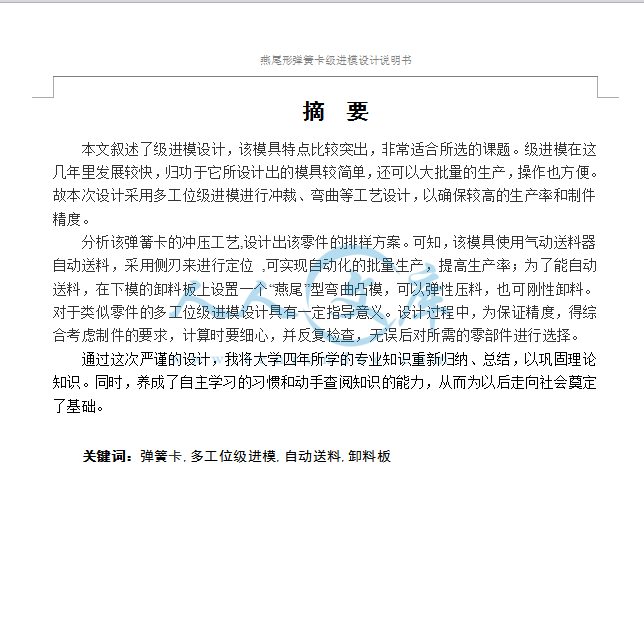
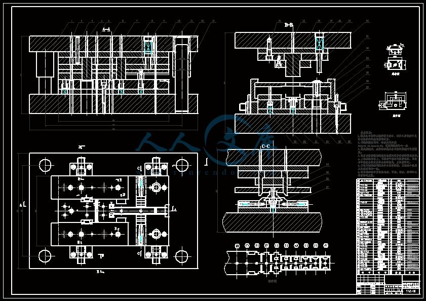


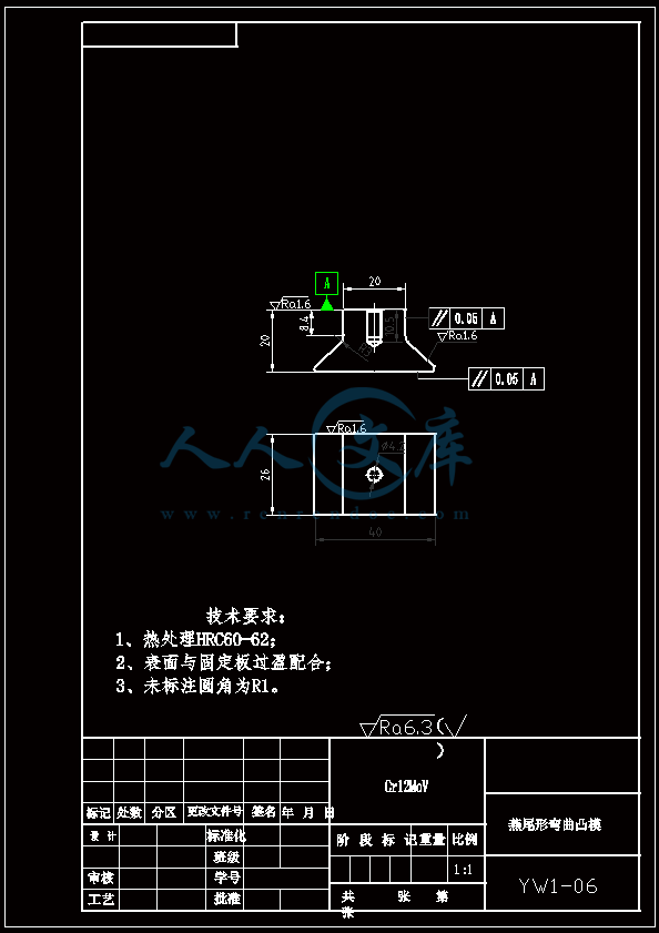


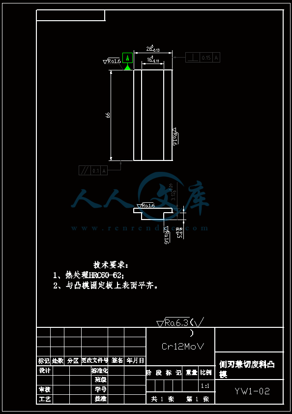
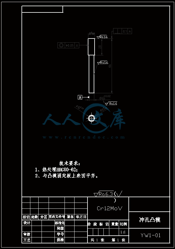

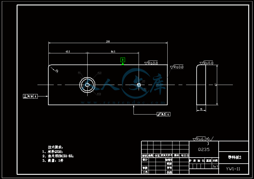
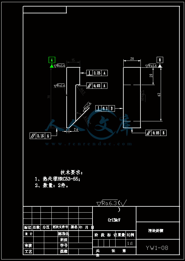
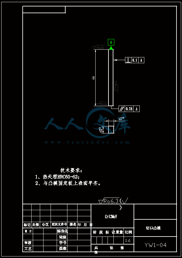
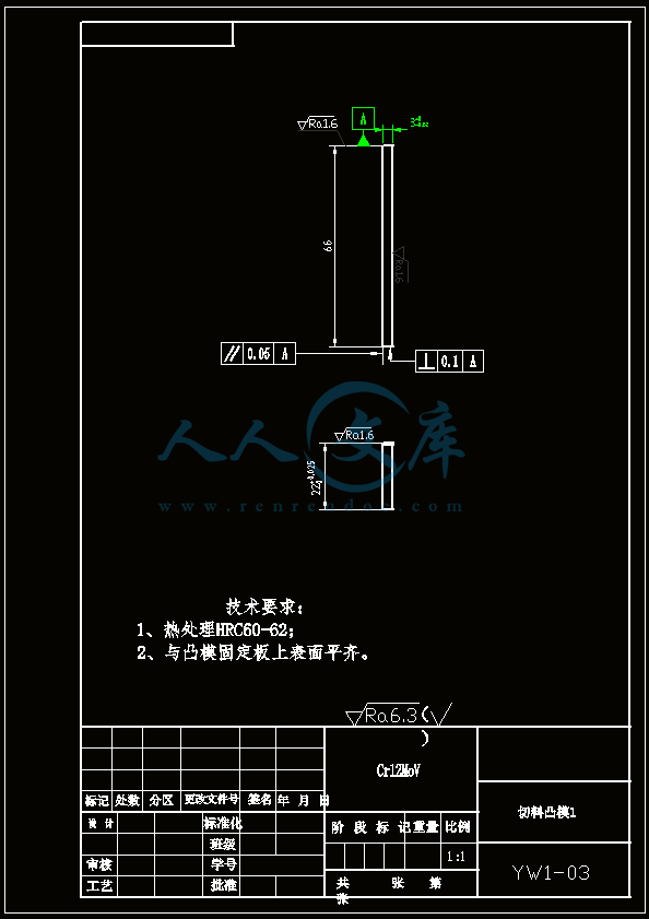

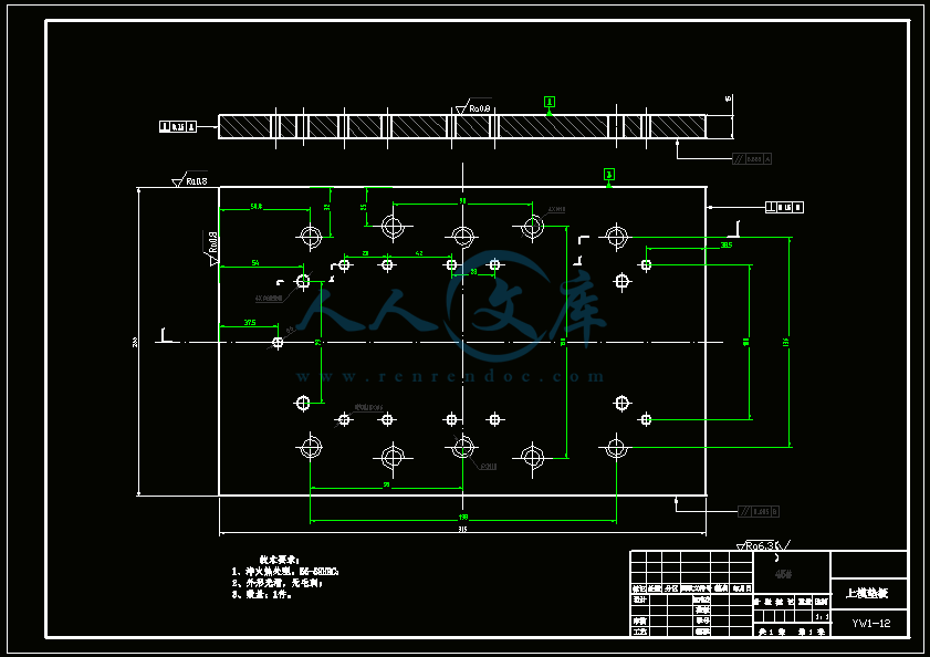
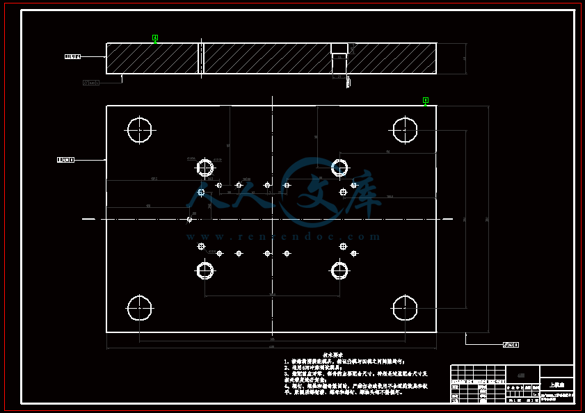
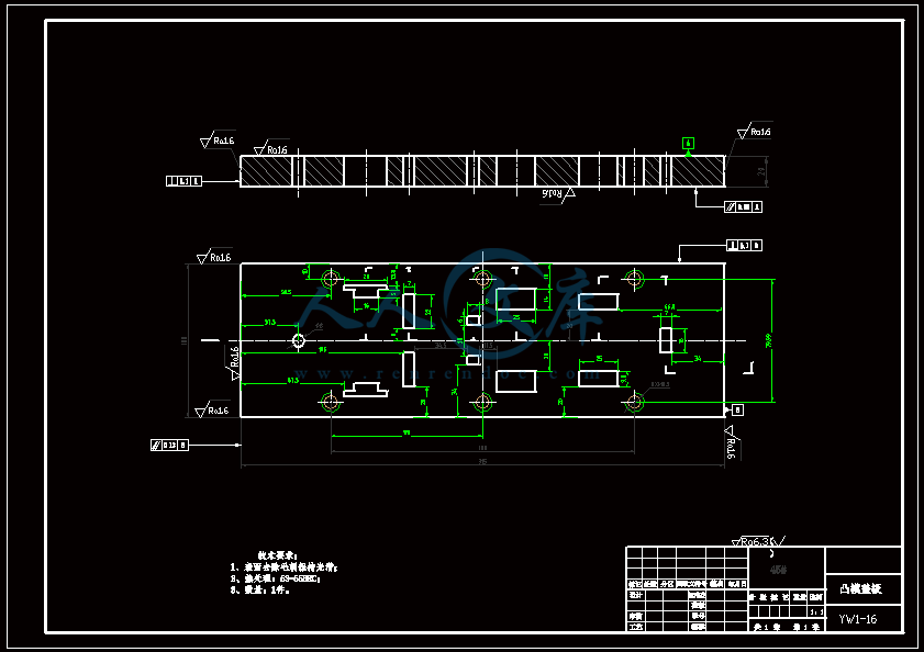
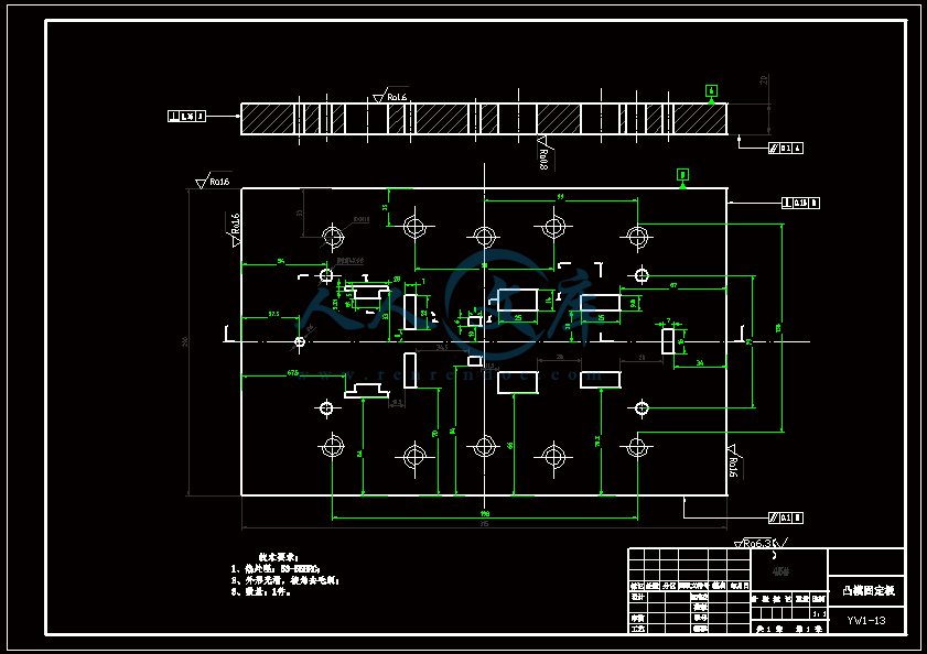
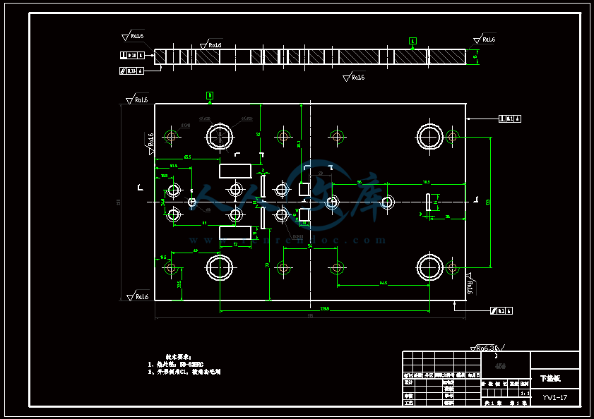
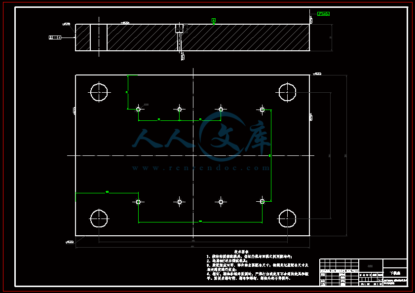
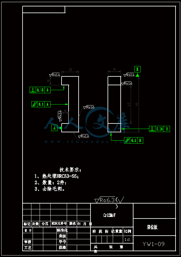
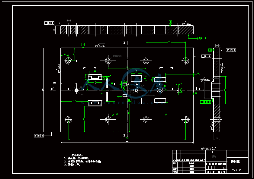
- 内容简介:
-
DOI 10.1007/s00170-004-2370-6 ORIGINAL ARTICLE Int J Adv Manuf Technol (2006) 28: 279285 R.D. Jiang B.T. Lauw A.Y.C. Nee Insertdesign automation for progressivedies Received: 19 June 2004 / Accepted: 11 August 2004 / Published online: 13 April 2005 Springer-Verlag London Limited 2005 Abstract Inserts are real operating components for producing sheet metal part features when the press moves up and down. The complexity, cost and durability of a progressive die de- pend largely on the number of inserts and the design of different groups of inserts. In addition, the accuracy of metal stampings also greatly relies on the structure of the functional insert groups and their assembly. Thus, the design of inserts is a critical op- eration to a designer in terms of the design quality and produc- tivity. In this paper, a fl exible and complete insert representation scheme has been proposed. The complex assembly relationships and constraints between inserts and components are analyzed. The design automation of inserts using the knowledge-based ap- proach is introduced. Finally, some results obtained using the proposed approach are given. Keywords Insert design Knowledge-based system Progressive die 1 Introduction A progressive die is an effective tool for the effi cient and eco- nomical production of sheet metal components in large quanti- ties. A progressive die combines two or more types of dies into a single tool in an attempt to perform as many operations as pos- sible in a single stroke of the press. With the rapid growth in R.D. Jiang (u) Institute of High Performance Computing, 1 Science Park Road, #01-01 The Capricorn, Singapore Science Park II, 117528, Singapore E-mail: jiangrd.sg Tel.: +65-64191503 Fax: +65-64191280 B.T. Lauw Molex Singapore Pte Ltd., Singapore A.Y.C. Nee Department of Mechanical Engineering, National University of Singapore, Singapore the computer technology, tele-communications and electronics markets, there is an increasing demand for sophisticated metal stampings and plastic parts. To improve the productivity of the die designer, researchers all over the world have spent a tremen- dous amount of time and effort trying to develop computer aided design (CAD) and manufacturing systems for press tools. In early research effort, computers were mainly used to improve productivity in drawing and to perform particular design calcu- lations and Numeric Control (NC) programming. Most of the important decisions, such as the design of punch shapes, the as- sessment of formability and the development of the strip layout, were still made interactively by the user. This is because consid- erable human expertise was not incorporated into the system. Sincethelate1980s, researchersfromseveraluniversitiesand research institutes have built progressive-die design automation systems with artifi cial intelligence (AI) technology 15. How- ever,thefunctionalitiesofthosesystemsarequitelimitedandthey caneitherhandle partsrequiring onlypiercing andblanking oper- ations, or parts that have relatively simple geometry. Some of the systemsare designed only forspecializedproducts. Suchsystems require a high degree of input by experienced designers during the design process 6. Recently, some research works have been reported on automated CAD systems, computer aided process planning for electric products 7,8, and Computer Aided De- sign/Computer Aided Process Planning/Computer Aided Manu- facturing (CAD/CAPP/CAM) integration for progressive die de- sign and manufacturing 9,10. Very few of them, however, have focused on the systematic insert representation and design au- tomation for the reduction ofdesign lead-time. To develop a progressive die design system with a high de- gree of automation, fl exibility and accuracy, it is essential to have a systematic representation of the related objects and pro- cesses from the initial modeling to the fi nal output. In addition, the complex interrelations among different objects, components and assembly must be set up so that various constraints and as- sociations can be kept automatically in the design and editing processes. This is especially important for the productivity im- provement because the change of design occurs very often due to either the change of product or the change of layout and tooling 280 structure. Based on the systematic object models, rules and algo- rithms must be incorporated into the system to facilitate design automation and confi guration. This paper focuses on the design automation of inserts, which are the real operating components and account for a large portion in the entire design procedure. The complexity, cost and durability of a progressive die depend largely on the number of inserts and the design of different groups of inserts. In addition, the accuracy of metal stamping products also greatly relies on the structure of functional insert groups and their assembly. Thus, the design of inserts is critical to a designer in terms of the de- sign quality and productivity. This paper fi rst presents a fl exible and complete insert representation scheme using object-oriented and feature-based methodology. The complex assembly relation- ships and constraints between inserts and components are then analyzed. The design automation of inserts using the knowledge- based approach is introduced. Finally, some results obtained using the proposed approach are given. 2 Feature-based description of inserts 2.1 Object-oriented design of insert objects Object-oriented methodology (OOM) is a philosophy that fo- cuses on objects that form the system with their own internal states and movement pattern. An object is any distinguishable component of a system which has a set of attributes that de- fi ne its state and a set of methods for manipulating that state, as shown in Fig. 1 11,12. The objects of a system can be di- vided into groups where each group share related characteristics. Each group of objects is called an “object class”. It is the com- position and interaction of the different objects that form the system which we want to research and analyze. Object-oriented methodology has four basic characteristics: data abstraction, en- capsulation, inheritance and communication by message passing. The ultimate objective of OOM is application assembly: the constructionofnewbusinesssolutionsfromexistingcomponents. The components are combined in different ways to meet the new requirements specifi ed by the user community. Only completely new functionality will have to be built tocomplete the solution. Fig.1. Object internal view Functionally, inserts can be classifi ed as punch insert, die in- sert, stripper bush, clamping insert, etc. Every category of these inserts has different function. Based on the different stamping operations, inserts can be divided into piercing insert, blanking insert, bending insert, burring insert, embossing insert, etc. For acomplete descriptionofalltheseinserts,itisnecessarytogather the common features of these inserts so that the design and as- sembly of these inserts can be easily carried out. From the ex- tended perspective of insert design, a generic insert is composed ofthe following three groups ofattributes: (1) drawing-related at- tributes; (2) fundamental components; and (3) assembly-related constraint attributes. The schematic representation of insert ob- jects is shown in Fig. 2. For a drawing-related attribute, it is very commontoincludethetypeofmaterial,thehardnessrequirement, the quantity of this insert, a description, and revision informa- tion. Allthis information is very important forautomatic drawing generationandthecreationofbillofmaterials.Thecomponentat- tribute is the core feature in insert confi guration. It consists of the mainbody ofthe insert,the shoulder, reliefforother components, screw, ejectorand transferpin, etc. The body of an insert is composed of a series of 3D geo- metric features. Three types of geometry relations are defi ned: union, subtraction, and side-to. Consider the relations for two features faand fb. The union feature fucontains the elements of faand fb, while the subtraction feature fscontains only the elements remaining after removing fbfrom fa. The side-to rela- tionship indicates the relationship between a face feature and an entity feature 13. The body composition of a coining die insert is shown in Fig. 3. This die insert consists of base block (body0), a pilot hole (body1) and the head of coining (body2). The geo- metric relationship of body0 and body1 is subtraction, while the Fig.2. Schematic representation of an insert object 281 Fig.3. Feature-based geometric representation of an insert body relationship between body0 and body2 is union, and the upper face of body0 is a side-to relationship with body2. 2.2 Shoulder of inserts A shoulder is basically one type of body objects. The reason why it is defi ned as a special object is that it is widely used in the de- sign of inserts. With the defi nition of this object, some design methods and rules can be incorporated into this object to ease the design and simplify the complexity of the insert. Just like the basic body, a shoulder can be positive or negative to an in- sert. According to this relationship and whether or not there is an opening for the shoulder on plate, four types of shoulders have been defi ned as shown inFig. 4. Type A is a shoulder witha posi- tive body on the insert, and there is a corresponding reliefhole on the plate for this shoulder; Type B is the case of a negative body, and there is no relief hole on the plate; Type C is of a shoulder with a positive body, however, there is no relief hole on the plate this is because the shoulder is mating with a negative shoul- der of another component; Type D can be seen as a shoulder with a height equal to the plate thickness. A through hole is needed as a relief hole for this shoulder. For the automatic design of shoulders, three types of rules can be encapsulated into the shoulder object: (1) confi guration Fig.4. Shoulder component and its relationship with the plate Fig.6. Some assembly types of screws Fig.5. Object-oriented representation of screw object of geometric body; (2) undercut calculation of the shoulder; and (3) opening design for this shoulder. 2.3 Screw of inserts A screw is another widely used component in progressive die design. It is a standard component used to fi x or tighten differ- ent objects in the die assembly. In terms of the representation structure, a screw object is relatively simple. The object-oriented representation of the screw object is shown in Fig. 5. The attribute of the screw object includes the type of screws, assembly type, diameter, length, position, etc. The method “Se- lectMethod” is used to design the fastener. When this method is fi red, the selection procedure “SelectFastener” is called and a standard fastener will be matched from the standard compon- ent library. There are some rules on how to apply fasteners, for instance, spacing of fasteners, holes for screws, etc. The mapping is based on the type of screw and the key parameters described in this structure. For example, if the MISUMI catalogue is used and the type is “CB”, then the CounterBoreFastener in the MIS- UMIcatalogue issearchedandmatched.Therearemanymethods to apply screws 14. According to the assembly of screws with theircomponents, sometypesofassembliesareintroduced todis- tinguishdifferentassemblyrelationshipsbetweenthefastenerand thecomponent.Thisisveryusefulfortheautomaticmatchingand confi gurationofthefasteneranditsassembly.Figure 6showssev- eral types of assembly for fasteners. Type A, Type B, Type E and 282 Type Fare the caseswithstepholes on thefi rstcomponents. Type BandTypeDareusedfortheholeswiththreads.TypeEandType F are some variations ofopenings onthe secondcomponents. 3 Assembly model of inserts As illustrated in the last section, the inserts defi ned in this paper are actually a subassembly of its sub-components, such as insert body, screws, ejectors, dowel pins, etc. This section will address the sub-assembly of group inserts and plates. This is a higher- level relationship between inserts and plates. To ensure that a product feature is produced smoothly and accurately, every insert must maintain a complex assembly rela- tionship with different plates and components, as well as other inserts in the same functional group. These complex interrela- tionships can be classifi ed twofold: (1) assembly with plates. One insert can possibly have an assembly relationship with sev- eral plates. For instance, in a typical die set, a punch insert has to maintain its assembly relations with the punch holding plate, Fig.7. a Sub-assembly of plate (horizontal) b Sub- assembly of functional insert group (vertical) Fig.8. Hierarchical model of die assembly and insert sub-assembly stripper backup plate and stripper yoke, or the insert compo- nents on these plates. If there are knockouts for the punch insert, additional plates considered are the punch backup plate and up- per die shoe. Figure 7a illustrates the assembly relationship of a plate with its relevant inserts. (2) Assembly with the func- tional group inserts performing on the same sheet metal features. For example, the group of inserts of cutting operations that per- forms the hole feature may include a punch, a die, a stripper bush and a key insert for the punch. In addition, some die in- serts and stripper bushes may be split into several inserts for manufacturing purposes. Therefore, a sheet metal feature may need a number of inserts operating together. This relationship can be viewed as a vertical assembly with the inserts in the same group, as shown in Fig. 7b. To maintain this vertical assembly and associations, it is good practice to group these inserts under an operation feature. When the operation feature is modifi ed or moved, its corresponding group of inserts must be changed or moved accordingly. Therefore, the whole die assembly can be viewed as two major assembly relationships. One is the plate sub-assembly, 283 which is considered to be a horizontal relationship of inserts and plates in this research. Another is the sub-assembly of the functional insert group, as shown in the example of Fig. 7b. The plate sub-assembly is categorized into the sub-assembly of stan- dard components and the sub-assembly of non-standard compo- nents. Non-standard component sub-assembly and insert group sub-assembly may refer to the same insert, which in turn is a sub-assembly of insert components (parts). The hierarchical as- sembly relationship of a die assembly is shown in Fig. 8. 4 Knowledge-based design of inserts The preliminary requirement for insert design is that the die structure and operation features be defi ned. This is because the insert has a complex assembly relationships with both plates and operations, as discussed in previous section. For example, for a typical die structure, the length of cutting punch is determined by the thickness of the punch holding plate, stripper backup plate and stripper plate, as shown by the following equation: Lp= f(TPHP,TBTP,TSTP,tBDC,t,dslot) where f is the function for length calculation of cutting punch, Lpis the length of punch, TPHP, TBTPand TSTPare the thickness of punch holding plate, stripper backup plate and stripper plate respectively, tBDCis the bottoming dead center , t is the thickness of sheet metal, and dslotis the slot depth of the stripper plate. Based on the representation of the insert shown in Fig. 2, the design of inserts naturally includes the following practice: 1. Drawing related attribute determination 2. Base body (geometry) design based on certain rules or algorithms 3. Component design based on the function of the insert 4. Assembly confi guration of the insert The process can be described by operation features. For a particular operation feature, it is necessary to fi rst construct all the inserts needed for this operation, and then to confi gure the assembly relationship with plates and other components. The confi guration sequence of inserts in the same function group can be described by the following: 1. Identify one operation in the sequence of station 2. Design punch insert 3. Design die insert, if any Fig.10. Sample algorithms for auto-confi guration of the insert profi le Fig.9. Sample insert design rules for an extrusion operation 4. Design stripper bush, if any 5. Design clamp insert, if any 6. Design other insert, if any 7. Split inserts of this group, if necessary This process can be automated with the rules and algorithms embedded in the various insert objects. This automation is im- portant and will reduce the design lead-time signifi cantly be- cause the design of inserts accounts for a large portion of the entire design cycle. Figure 9 shows the sample insert (punch) design rules for the extrusion operation. The rules are used to determine the burring punch type and its diameter for an extrusion operation. Figure 10 shows several types of algorithms for the calcula- tion of insert profi les. Together with criteria for the selection of different algorithms, insert profi les can be automatically gener- ated. The area with hatching lines in this fi gure is the working area. Type A is computed based on the extent of working area with safety offsets to every side; Type B is controls overall size of the insert; Type C provides a way to control the dimensions of the centroid point of the working area to the edges of the insert; and Type D is similar to type A, except that the vertical offsets c and d are relative to the edges of the sheet metal. In addition, there may exist a modifi cation to every corner of the insert. The function can be described as follows: M = fij(t, p) where i (L, R), j (T, B), there are four possible combina- tion of ij: LT, LB, RT and RB represents the four corners of 284 insert profi le: left-top, left-botto
- 温馨提示:
1: 本站所有资源如无特殊说明,都需要本地电脑安装OFFICE2007和PDF阅读器。图纸软件为CAD,CAXA,PROE,UG,SolidWorks等.压缩文件请下载最新的WinRAR软件解压。
2: 本站的文档不包含任何第三方提供的附件图纸等,如果需要附件,请联系上传者。文件的所有权益归上传用户所有。
3.本站RAR压缩包中若带图纸,网页内容里面会有图纸预览,若没有图纸预览就没有图纸。
4. 未经权益所有人同意不得将文件中的内容挪作商业或盈利用途。
5. 人人文库网仅提供信息存储空间,仅对用户上传内容的表现方式做保护处理,对用户上传分享的文档内容本身不做任何修改或编辑,并不能对任何下载内容负责。
6. 下载文件中如有侵权或不适当内容,请与我们联系,我们立即纠正。
7. 本站不保证下载资源的准确性、安全性和完整性, 同时也不承担用户因使用这些下载资源对自己和他人造成任何形式的伤害或损失。

人人文库网所有资源均是用户自行上传分享,仅供网友学习交流,未经上传用户书面授权,请勿作他用。
 川公网安备: 51019002004831号