1500031贾吉林296448.pdf

GQ50型钢筋切断机主传动机构的设计与运动仿真[三维proe][20张CAD图纸+文档]

收藏

资源目录
跳过导航链接。
GQ50型钢筋切断机主传动机构的设计与运动仿真[三维proe][20张CAD图纸文档].zip
说明书.doc---(点击预览)
摘要目录.doc---(点击预览)
开题报告.doc---(点击预览)
参数.doc---(点击预览)
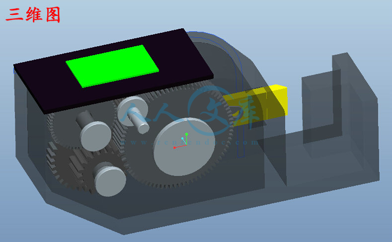
三维图.jpg---(点击预览)
三维图
asm00001.asm.1
asm00001__out.log.1
asm0001.asm.16
asm0001.asm.17
asm0002.asm.1
asm0004.asm.2
ban1.prt.1
ban2.prt.1
ban2.prt.2
c2.prt.1
c2.prt.2
c2.prt.3
gai1.prt.1
gai1.prt.2
gai2.prt.1
gan1.prt.1
gan1.prt.2
gear2.IGS
gear2.prt.1
gear3.IGS
gear3.prt.1
gear3.prt.2
gear3.prt.3
jian1-quzhou.prt.1
kuai1.prt.1
prt0003.prt.1
prt0003.prt.10
prt0003.prt.11
prt0003.prt.12
prt0003.prt.13
prt0003.prt.14
prt0003.prt.15
prt0003.prt.16
prt0003.prt.17
prt0003.prt.18
prt0003.prt.19
prt0003.prt.2
prt0003.prt.20
prt0003.prt.21
prt0003.prt.22
prt0003.prt.23
prt0003.prt.3
prt0003.prt.4
prt0003.prt.5
prt0003.prt.6
prt0003.prt.7
prt0003.prt.8
prt0003.prt.9
quzhou.prt.1
quzhou1.prt.1
std.out
trail.txt.1
trail.txt.10
trail.txt.11
trail.txt.12
trail.txt.13
trail.txt.14
trail.txt.15
trail.txt.16
trail.txt.17
trail.txt.18
trail.txt.2
trail.txt.3
trail.txt.4
trail.txt.5
trail.txt.6
trail.txt.7
trail.txt.8
trail.txt.9
youchi.prt.1
youchi.prt.2
youdonggear.IGS
youdonggear.prt.1
zhou1.IGS
zhou1.prt.1
zhou1.prt.2
zhou1.prt.3
zhou1.prt.4
zhou1.prt.5
zhou2.IGS
zhou2.prt.1
zhou2.prt.2
zhou2.prt.3
zhou2.prt.4
zhou3.IGS
zhou3.prt.1
zhou3.prt.2
zhuangpeitu.stp
外文文献
1轴.dwg
2轴.dwg
2轴大齿轮.dwg
3轴.dwg
3轴大齿轮.dwg
GQ50视频仿真.mpg
固定刀片.dwg
垫板.dwg
大侧盖.dwg
大带轮.dwg
带台轴瓦.dwg
无台轴瓦.dwg
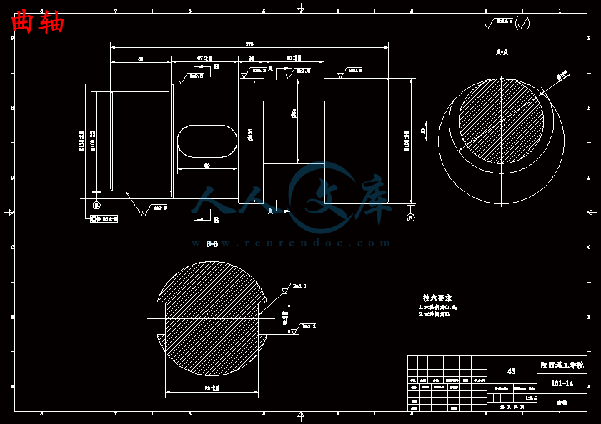
曲轴.dwg
活动刀座.dwg
活动刀片.dwg
游动大齿轮.dwg
装配图.dwg
连杆.dwg
连杆配合部分.dwg
连杆铜瓦.dwg
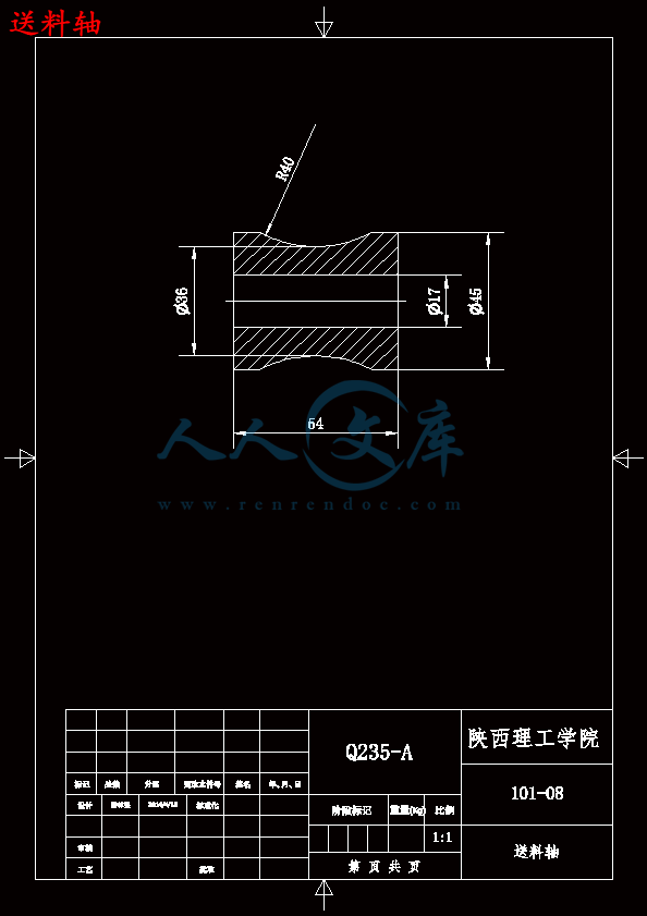
送料轴.dwg
压缩包内文档预览:
预览图 预览图 预览图 预览图 预览图 预览图 预览图 预览图 预览图 预览图 预览图
编号:13756814    类型:共享资源    大小:32.65MB    格式:ZIP    上传时间:2019-01-25 上传人:好资料QQ****51605 IP属地:江苏
50
积分
关 键 词:
三维proe 20张CAD图纸+文档 gq50 型钢 切断 割断 机主 传动 机构 设计 运动 仿真 三维 proe 20 cad 图纸 文档
资源描述:

【温馨提示】 购买原稿文件请充值后自助下载。

以下预览截图到的都有源文件,图纸是CAD,文档是WORD,下载后即可获得。


预览截图请勿抄袭,原稿文件完整清晰,无水印,可编辑。

有疑问可以咨询QQ:414951605或1304139763

    GQ50钢筋切断机结构设计与运动仿真


【摘要】

  钢筋切断机是把钢筋切成所需长度的专用机械,在大型建筑工地上的应用非常广泛。钢筋切断机分为机械传动和液压传动两种。机械传动式钢筋切断机,工作时大都采用电动机经一级三角带传动和三级齿轮传动减速后,带动曲轴旋转,曲轴推动连杆使滑块和动刀片在机座的滑道中作往复直线运动,使活动刀片和固定刀片相错而切断钢筋。GQ50型钢筋切断机,其剪切运动是由一偏心轮连杆机构完成的。但是由于切断机机体内腔狭小,在装配曲轴连杆时比较困难。尤其是在使用中发生故障需要维修时,拆卸曲轴连杆更加不容易,给维修造成很大的不变,因此在不改变设备功能的情况下,我对曲轴连杆机构做了一些改进。改进后的偏心轮结构直接从机体的注册孔中装入和取出。而不必拆卸连杆,大大简化了装配程序,减轻的工人的劳动强度。同时也极大的方便了维修,还简化了零件的工艺过程,取得良好的经济效益。

【关键词】:钢筋切断机;偏心轮;曲轴连杆机构


GQ50 reinforcing steel cutter structural design and movement simulation


    Abstract

    Reinforcing steel cutting machine is used to cut the required length of steel machinery specialized for large construction sites in the application of very extensive. Reinforcing steel cutting machine into mechanical transmission and hydraulic transmission of two. Mechanical transmission reinforced cutting machine, working mostly used as a V-belt drive motor and gear drive slow down after three, driven crankshaft rotation, promoting the crankshaft and connecting rod to move the slider blade in the frame of the chute in a reciprocating linear motion So that the activities of the blade and a fixed blade and cut off the wrong steel. GQ50-steel cutter, whose movement from one type of the crankshaft linkage to complete. However, due to cut off the small inner cavity of the body, in the assembly when the crankshaft link more difficult. Especially in the use of a fault in need of repair, demolition crank link more difficult to repair a big change, so do not change the function of the equipment under the circumstances, we have made some improvement to crank linkage. The improved structure of the cam directly from the body of the aircraft registered in the hole and packed out. Without dismantling the link, greatly simplifies the assembly, reducing labor intensity of workers. But also greatly facilitate the maintenance, has also simplified the process of parts and achieved good economic returns.

Key words: steel cutting machine, the structure design, proe, virtual assembling, movement                          

                 simulation  


目录

1 绪论 1

1.1 钢筋切断机的研究现状 1

1.2 本次设计的任务 2

1.3 本次设计目的与意义 3

2 钢筋切断机的总体设计 4

2.1 钢筋切断机的基本介绍 4

2.2 GQ50型钢筋切断机的改良方向 5

2.3钢筋切断机的工作原理 6

2.4 钢筋切断机的基本结构 6

2.4.1 GQ50型钢筋切断机主传动机构的设计方案的确定 6

2.4.2 GQ50型钢筋切断机主传动机构设计的基本思路 7

2.4.3 GQ50型钢筋切断机主传动机构设计的方法 7

3 方案设计比较 8

3.1驱动装置方案选择 8

3.1.1液压驱动 8

3.1.2 手动驱动 8

3.1.3 电机驱动 8

3.2传动装置方案选择 9

3.2.1 液压传动 9

3.2.2 带传动 9

3.2.3 齿轮传动 9

3.2.4 组合传动 9

3.3执行装置方案选择 9

3.3.1曲柄滑块机构 9

3.3.2齿轮齿条机构 10

3.3.3凸轮机构 10

4 钢筋切断机传动设计 12

4.1电动机的选择 12

4.2 基本传动数据计算 12

4.2.1传动比的分配 12

4.2.2 各轴的运动及动力参数分析 13

4.3 带传动的设计 14

4.3.1带型的选择 14

4.3.2带轮基准直径的确定 14

4.3.3带速的确定 15

4.3.4中心距、带长及包角的确定 15

4.3.5确定带的根数 16

4.4 齿轮传动的设计 16

4.4.1选材料、确定初步参数 16

4.4.2齿面疲劳强度计算 18

4.4.3齿根抗弯疲劳强度验算 20

4.5 轴的设计 21

4.6键的选取与校核 22

4.6.1键的选取 22

4.6.2键强度的校核 22

4.7轴承的组合设计 23

4.8连杆的设计 24

4.9切断钢筋需用力计算 24

4.10减速器附件的选择 25

5 钢筋切断机的摩擦、磨损和润滑 26

6 机械式钢筋切断机调整及保养的使用 27

6.1 钢筋切断机的使用调整 27

6.2 钢筋切断机的保养 28

6.3钢筋切断机的一般安全的规定 29

7 建模与仿真 30

7.1 三维软件的介绍 30

7.2 钢筋切断机的建模与仿真 31

7.2.1 钢筋切断机主要零件的三维建模 31

7.2.2 GQ50型钢筋切断机主传动机构的装配与仿真 40

致谢 43

参考文献 44


内容简介:
ORIGINAL ARTICLE CAD-based simulation of the hobbing process for the manufacturing of spur and helical gears V. Dimitriou&A. Antoniadis Received: 20 May 2007 /Accepted: 28 February 2008 / Published online: 29 April 2008 #Springer-Verlag London Limited 2008 Abstract Targeting an accurate and realistic simulation of the gear hobbing process, we present an effective and factual approximation based on three-dimensional computer-aided design. Hobbing kinematics is directly applied in one gear gap. Each generating position formulates a spatial surface path which bounds its penetrating volume into the workpiece. The three-dimensional surface paths generated from the combina- tionoftherelativerotationsanddisplacementsofhobandwork gear are used to split the subjected volume, creating concur- rently the chip and the remaining work gear solid geometries. ThedevelopedsoftwareprogramHOB3Dsimulatesaccurately the manufacturing of spur and helical gears, exploiting the modeling and graphics capabilities of a commercial CAD software package. The resulting three-dimensional solid geometrical data, chips and gears provide the whole geomet- ricalinformationneededforfurtherresearch,suchasprediction of the cutting forces, tool stresses and wear development as well as the optimization of the gear hobbing process. Keywords Gearhobbing.Manufacturingsimulation. CADmodeling 1 Introduction Gear hobbing is a widely applied manufacturing process for the construction of any external tooth form developed uniformly about a rotation center. Compared to conven- tional machining, such as turning and milling, the hobbing process is a sophisticated metal removal technology. Whileit is the most widely used process for the roughing of gears, its complexity and cost keep this technique poorly known. The kinematics principle of the process is based on three relative motions between the workpiece and the hob tool. For the production of spurs or helical gears, the workpiece rotates about its symmetry axis with a certain constant angular velocity, synchronized with the relative gear hob rotation. The worktable or the hob may travel along the work axis with the selected feed rate, depending on the hobbing machine that is used. For the simulation of the gear hobbing process variant approximations have been proposed for the development of numericalandanalytical models,aiming atthedetermination of the undeformed chip geometry, cutting force components and tool wear development 1, 2. The industrial weight of these three simulation results is associated with the optimization of the efficiency per unit cost of the gear hobbing process. The undeformed chip geometry is an essential parameter to determine the cutting force compo- nents, as well as to predefine the tool wear development, both of them important cost related data of hobbing process 3. For the effective specification of the tolerances on hob design parameters and allowable alignment errors, Kim 4 proposes a method of representing the geometry of a hob tooth profile in parametric form and of determining the surface equation of a generated gear as a function of hob design parameters and generating motion specifications through a mathematical model of the generation process. The simulation of meshing of face hobbed spiral bevel and hypoid gears and mathematic models of tooth surface generations are presented by Fan, and a tooth contact analysis program was developed 5. Int J Adv Manuf Technol (2009) 41:347357 DOI 10.1007/s00170-008-1465-x V. Dimitriou Technological Educational Institute of Crete, Chania, Crete, Greece A. Antoniadis (*) Technical University of Crete, Chania, Crete, Greece e-mail: antoniadisdpem.tuc.gr The research work presented in 611 provided the basic knowledge for the numerical modeling of the gear hobbing process and later on newer approximations were proposed based on a similar modeling strategy 1217. These approximation methods are proposed for the deter- mination of the hobbing process results, but the main characteristic of these methods is the reduction of the actual three-dimensional process to planar models, primarily for simplification reasons. The application of these former approximations is leading to planar results, without to represent the exact solid geometry of the real chips and gears, with accuracy directly dependent from various input parameters such as the number of the calculation planes. Furthermore, any post-processing of the extracted chip and gear planar geometries, e.g., finite element analysis, requires additional data processing which leads to supple- mentary interpolations of the two-dimensional results. Focusingontherealisticandaccuratesimulationofthegear hobbing process, without inevitable modeling insufficiencies, we present an approach for the simulation of manufacturing spur and helical gears in this research work. A software program called HOB3D, originally presented in 18, is used for the guidance of an existent commercial CAD system, exploiting its powerful modeling and graphics capabilities. HOB3D is built in terms of a computer code in Visual Basic, extending this capability to other cutting processes based on the same cutting principle. The resulting solid models output formats offer realistic parts, chips and work gears, easily managed for further individual research or as an input to any other CAD, CAM or FEA commercial software systems. 2 HOB3D modeling procedure The rolling principle between the hob and the workpiece makes the gear hobbing process different from conventional milling. As presentedin Fig. 1, the process problem is basically prescribed from the geometrical characteristics of the gear to be cut, the hob that will be used and the involved kinematics between them. The geometry of a resulting gear is basically described by six parameters: module (m), number of teeth (z2), outside diameter (dg), helix angle (ha), gear width (W) and pressure angle (an). The correlation of these parameters automati- cally yields the module (m) of the hob tool, whereas other tool geometrical parameters as external diameter (dh), number of columns (ni), number of origins (z1), axial pitch () and helix angle (), are options to be chosen. As soon as the geometrical parameters of the two combined parts are set, the kinematics chain has to be initialized. The helix angle of the hob and the work gear prescribe the setting angle (s) between the parts and the way that their relative motions will take place. Three distinct cutting motions are required: the tool rotation about its axis, the tool axial displacement and the workpiece revolution about its axis. By these means, the direction of the axial feed (fa) prescribes two different hobbing strategies: the climb (CL) and the up-cut (UC). In case of helical gears, two additional variations exist, the tool helix angle () compared to the helix of the gear (ha). If the direction of the gear helix angle is identical to the hob helix angle the type of the process is set to equi-directional (ED), if not to counter-directional (CD) one. As presented in Fig. 2, after the initialization of the input data the solid geometry of the work gear is created in the CAD environment and one hob tooth rake face profile is mathematically and visually formed. At the same moment the assembly of the effective cutting hob teeth (N) is determined and the kinematics of gear hobbing process is directly applied in one three-dimensional tooth gap of the Fig. 1 Essential parameters of gear hobbing 348Int J Adv Manuf Technol (2009) 41:347357 gear due to the axisymetric configuration of the problem. Moreover, a three-dimensional surface is formed for every generating position (e.g., successive teeth penetrations), combining the allocation of the hob and the work gear, following a calculated spatial spline as a rail. These three- dimensional surface paths are used to identify the unde- formed chip solid geometry, to split the subjected volume and to create finally the chip and the remaining work gear solid geometries. 3 HOB3D simulation strategy In this approach every rotation and displacement that is taking place between the hob and the work gear during the simulationoftheprocessaredirectlytransferredtothehob.As presented in Fig. 3, the global coordinate system of the two parts is fixed to the center of the upper base of the workpiece, providing a steady reference system to the travelling hob. The presented scheme of kinematics has been adopted and in previous numerical approximation research works, mentioned at the introduction. Without any loss of generality, the hob is considered to have a tooth numbered-named: Tooth 0. The identification vector v0of Tooth 0 has its origin CHon the Yhaxis of the hob and its end at the middle of the rake face, forming a module that equals to dh/2. This vector determines the direction of the Zhaxis of the hob coordinate system XhYhZhand is initially placed as an offset of the global Z-axis, set at a vertical distance L1from the origin of the L1: Vertical distance hob - gear L2: Horizontal distance hob - gear w o r k g e ar Z d E F G H O df ha Pitch circle d = helix arc of pitch circle da/2 2 df sin(h ) a mz2 Gear hobbing kinematics 1:angleHob rotation 2 : Gearanglerotation Fig. 3 HOB3D simulation kinematics scheme CAD based Gear Hobbing Simulation Program HOB3D * dh: outdiameter mmside Input Data Hob GeometryWorkgear GeometryCutting Conditions m : module mm z2: number of teeth ha: helix angle deg m : module mm ni: number of columns z1: number of hob origins dg: outside diameter mm fa: axial feed mm/wrev t : depth of cut mm v :m/min Calculations Generation of Workgear solid geometry Determination of N effective cutting teeth Generation of 3D-spline path of hob tooth Mathematical description of the hob tooth rake face workgear path of a hob tooth Gear hobbing process - Results 3D surface geometrical descriptio of the hob tooth kinematic For active teeth Computation of the underformed chip geometry . tooth profile spline tooth revolving direction n solid . . cutting speed Fig. 2 Flowchart of the program HOB3D Int J Adv Manuf Technol (2009) 41:347357349 fixed XYZ global system, determining the region where the cutting starts. Once the simulation parameters are settled, the work gear solid model is generated and the assembly of the effective cutting hob teeth is enabled. The moment that the gear hobbing simulation starts is considered as time zero. At this time (t=0) the planes YZ and YhZhare parallel and their horizontal distance, steady for the whole simula- tion period, is set to: L2 dh=2 dg=2 ? t. The distance L2practically determines the cutting depth, user defined as an input parameter. To determine the setting angle s, the XhYhZhhob coordinate system is rotated about the Xhaxis, so that the simulation process becomes completely prescribed. Using the spatial vector v0, it is easy to compute the identification vectors viof each of the N effective teeth relatively to v0, taking into account the hob geometrical CAD based Gear hobbing kinematics Y Z X Chip solid geometry identification Chip solid geometry Work gear chip cross section detail A hmax path of a hob tooth chip tooth cutting plane cutting plane A tooth revolving position rake face n1i CHi n2i dh hob revolving direction 3d spline path work gear work gear vi Fig. 4 Three-dimensional kinematics scheme in the CAD environment HOB3D algorithmic diagram Initialization of input data Initialization of program parameters Mathematical determination of Vector v0 Generation of Work Gear cylinder Mathematical determination of spatial vectors v , (C n ) and (C n ) iH1 iH2 i Application of forward kinematics to vectors v , (C n ) and (C n ) iH1 iH2 i Mathematical description of 3D spline points,3D planes and corresponding profiles Creation of 3D spline points, 3D planes and profiles, 3D spline trajectory Generation of i-cutting tooth 3D surface path Subtraction of i-chips solid geometry i = l i=f Numerical implementationCAD system implementation End NY i = i+1 Determination of N effective cutting teeth Fig. 5 Algorithmic diagram of the program HOB3D 350Int J Adv Manuf Technol (2009) 41:347357 input parameters. The independent parameter 1counts the rotational angle of hob tool about its axis Yhduring the cutting simulation. The parameter 2declares the rotational angle of the hob tool about the work gear and fathe axial feed of the hob. 2and faare dependent from 1and their values are determined according to the values of 1angle (see also the upper part of Fig. 3). The forward kinematics of each of the N effective cutting hob teeth occur in one gear tooth space (gap). Hereby, after the determination of v0and considering that the identification vector of the first of the N cutting hob tooth vfis determined relatively to v0,the forward kinematics are firstly applied to vfand sequentially to the following vectors vi, until the last cutting hob tooth of the work cycle vl, simulating precisely the real manufacturing process. In case of simulating helical gears fabrication, a differential angular amount is added on the rotating system of the gear, in order to increase or decrease the angular velocity of the rotating workpiece, ensuring the proper meshing of the hob-cutting and gear-cut angles. Depending on the type of the hobbing process a new angular parameter d has to be inserted to the whole kinematical chain for the acceleration or deceleration of 2. The calculation of the parametrical value of d is taking place on the pitch circle as it is detailed schematically presented in the lower part of Fig. 3, constituting a section of significant importance. As illustrated at Fig. 4, the prescribed kinematics chain is used for the construction of a three-dimensional spline path in the CAD environment. This spline path occurs from the interpolation of points generated from the vivector of the cutting hob teeth, that is properly transformed and rotated by the help of the simulation parameters 1, 2 and fa. Following the same tactic, the unit vectors (CHn1)i and (CHn2)i,described in the same Figure, are shifted and rotated for the generation of a plane properly positioned into the three-dimensional space, for every revolving position of the i-th cutting tooth. The profile of the cutting hob tooth is formed on the two-dimensional space that is created by each one of these Fig. 6 Maximum chip thickness on the revolving positions of every generating position of a full work cycle Int J Adv Manuf Technol (2009) 41:347357351 spatial planes, as presented in the middle of Fig. 4. By the proper lofting of the constructed open profiles following the rail of the constructed spatial spline, a three-dimensional open surface is created in one gear-gap tooth space. This surface path represents the generating position of the i-th cutting tooth and bounds its penetrating volume into the workpiece. With the aid of this surface path, the solid geometry of a chip is identified for every generating position, using the Boolean operations and the graphics capabilities of the CAD environment. The chip geometry is restricted by the external volume of the instantly formed working gear gap, bounded outside the created surface. The identified solid geometry is then subtracted from the workpiece leading to the generation of the continuous three-dimensional solid geometries of the chip and the remaining work gear. Because of the output form of the solid resulting parts of the simulation process, any kind of post-processing is primitively enabled. As can be seen at the lower right section of Fig. 4 in detail A, the maximum thickness of an extracted solid geometry of a chip at a certain revolving position is detected. All of the images presented in Fig. 4 were captured from the CAD environ- ment during a simulation performed from HOB3D. The words, phases and arrows were added afterwards with the help of commercial image processing software for the better explanation of the images. All of the previously mentioned simulation tasks are controlled by the developed program HOB3D that manipu- lates the modeling capabilities of the CAD system, forcing the generation of the geometrical entities in it, collecting the occurring geometrical data from it, and making all of the programmed numerical calculations. The continuous interac- tion of the CAD system with the numerical calculations environment of the program is algorithmically described at Fig. 5. After the insertion of the input data from the user the program parameters are initialized. The work gear cylinder geometry is generated and the number N of the effective cutting teeth is computed. The spatial vector v0is mathe- matically determined. The cutting tooth number parameter i is set to f (first cutting tooth number) and the vector viand the correspondent unit vectors (CHn1)iand (CHn2)i,essential for the construction of the spatial planes, are relative to v0 mathematically determined. The forward kinematics of the hobbing procedure is applied to these vectors. The resulting numerical data, prescribing the 3D spline points and the 3D planes, are used for the generation of the corresponding entities in the CAD environment.The generated 3Dpointsare interpolated for the construction of the 3D spline in the CAD environment. For each created spatial plane, the correspon- dent tooth profile is mathematically formed and sketched in the CAD system. The profiles are lofted properly, following the 3D spline trajectory forming the 3D surface path of the i-cutting tooth. The solid geometry included in the spatial surface is subtracted from the work gear and saved as the i-chip geometry (see the enlargement detail of Fig. 4). The i-counter takes the value i+1 and the same procedure is repeated until i became equal to l (last cutting tooth number). For the reduction of the computational effort and time, the overall rotation of the hob about its
温馨提示:
1: 本站所有资源如无特殊说明,都需要本地电脑安装OFFICE2007和PDF阅读器。图纸软件为CAD,CAXA,PROE,UG,SolidWorks等.压缩文件请下载最新的WinRAR软件解压。
2: 本站的文档不包含任何第三方提供的附件图纸等,如果需要附件,请联系上传者。文件的所有权益归上传用户所有。
3.本站RAR压缩包中若带图纸,网页内容里面会有图纸预览,若没有图纸预览就没有图纸。
4. 未经权益所有人同意不得将文件中的内容挪作商业或盈利用途。
5. 人人文库网仅提供信息存储空间,仅对用户上传内容的表现方式做保护处理,对用户上传分享的文档内容本身不做任何修改或编辑,并不能对任何下载内容负责。
6. 下载文件中如有侵权或不适当内容,请与我们联系,我们立即纠正。
7. 本站不保证下载资源的准确性、安全性和完整性, 同时也不承担用户因使用这些下载资源对自己和他人造成任何形式的伤害或损失。
提示  人人文库网所有资源均是用户自行上传分享,仅供网友学习交流,未经上传用户书面授权,请勿作他用。
关于本文
本文标题:GQ50型钢筋切断机主传动机构的设计与运动仿真[三维proe][20张CAD图纸+文档]
链接地址:https://www.renrendoc.com/p-13756814.html

官方联系方式

2:不支持迅雷下载,请使用浏览器下载   
3:不支持QQ浏览器下载,请用其他浏览器   
4:下载后的文档和图纸-无水印   
5:文档经过压缩,下载后原文更清晰   
关于我们 - 网站声明 - 网站地图 - 资源地图 - 友情链接 - 网站客服 - 联系我们

网站客服QQ:2881952447     

copyright@ 2020-2025  renrendoc.com 人人文库版权所有   联系电话:400-852-1180

备案号:蜀ICP备2022000484号-2       经营许可证: 川B2-20220663       公网安备川公网安备: 51019002004831号

本站为文档C2C交易模式,即用户上传的文档直接被用户下载,本站只是中间服务平台,本站所有文档下载所得的收益归上传人(含作者)所有。人人文库网仅提供信息存储空间,仅对用户上传内容的表现方式做保护处理,对上载内容本身不做任何修改或编辑。若文档所含内容侵犯了您的版权或隐私,请立即通知人人文库网,我们立即给予删除!