中英文文献翻译-衍射微结构的模具加工与注射成.docx
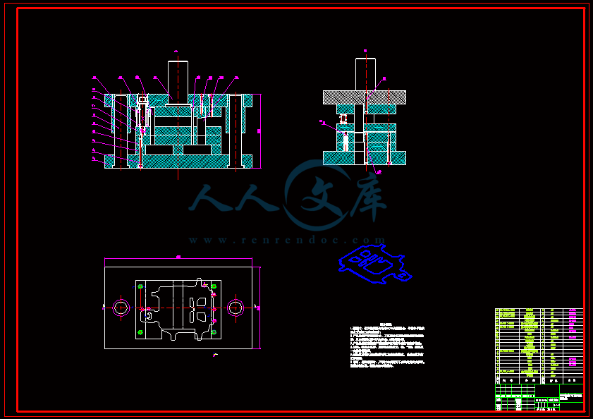
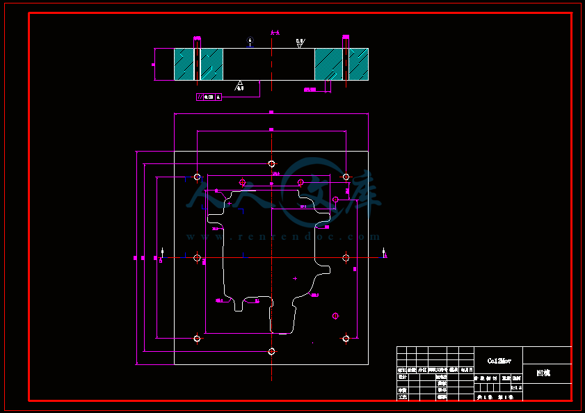
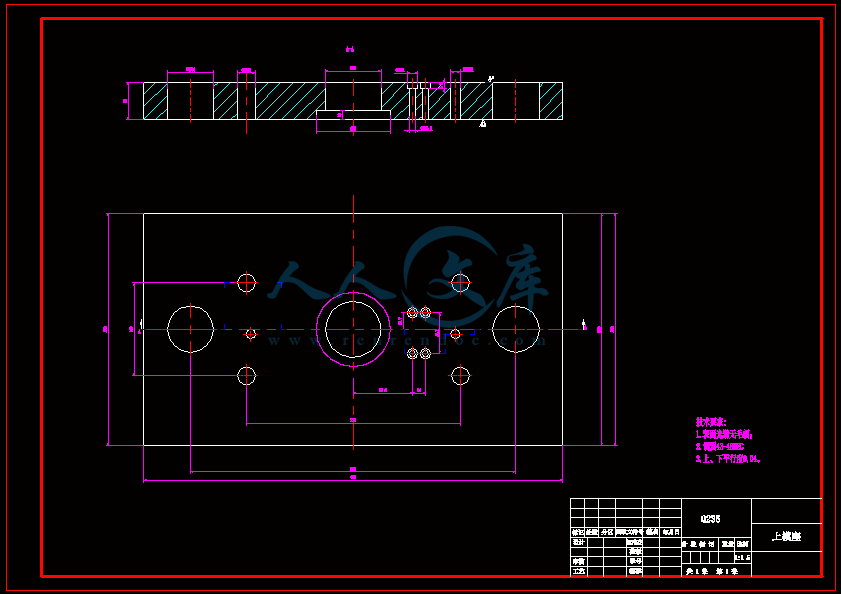
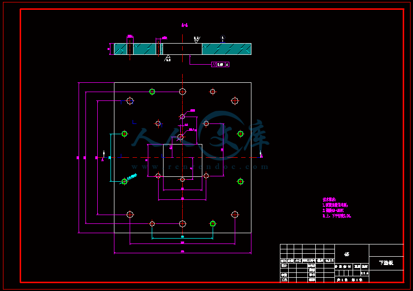
N400加油口门加强板冲压模设计【含CAD图纸、说明书】
收藏
资源目录

压缩包内文档预览:(预览前20页/共25页)
编号:14473856
类型:共享资源
大小:7.21MB
格式:ZIP
上传时间:2019-02-08
上传人:机****料
认证信息
个人认证
高**(实名认证)
河南
IP属地:河南
30
积分
- 关 键 词:
-
含CAD图纸、说明书
n400
加油
加强
冲压
设计
cad
图纸
说明书
仿单
- 资源描述:
-








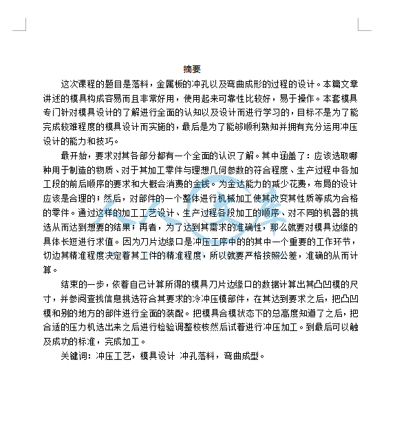
- 内容简介:
-
外文翻译 学 院 专 业 班 级 学 号 姓 名 衍射微结构的模具加工与注射成形 摘要:衍射显微结构用于许多应用,由于其独特的光学功能,例如作为钞票或文件的安全特征。通过开发更复杂的微观结构几乎不能复制,可以防止假冒的保护。本文介绍了一改进的金刚石车削工艺加工此类功能微结构。快速工具伺服辅助金刚石车削过程,使加工全息图组成属于具有叠加图案的衍射微结构。由此产生的结构是能够塑造事件光线进入定义的强度分布。这样的全息图可以用作安全标签或是塑料包装的有价值的产品。为了使这项技术接近群众生产,通过注塑成型的微观结构的复制是必不可少的。探讨举一反三通过注射成型,一个闪耀的结构是钻石变成一个模具,相同的基本的全息图结构。三光聚合物(PMMA,环烯烃共聚物COC,环烯烃聚合物COP)被用于注射成型的实验研究这个模具的填充行为与衍射微观结构的复制质量。 2017对制造工程师学会代表爱思唯尔公司出版。 1.介绍 衍射微结构提供独特的光学性能和用于各种各样的应用。从经典光谱光栅和眼内透镜的安全特性在纸币上,可以实现复杂的光学功能 1 。特别是对安全应用,不断改进和高功能的组织必须确保足够的有效的防止伪造。复杂性和由此微观结构的功能在很大程度上取决于机床的运动选择与精度。常见的衍射结构加工的制造工艺光刻,激光加工或金刚石加工,这是DIS划分小结构尺寸和工作波长短。 2 。金刚石加工工艺已被证明是合适的用于加工非连续微结构和自由曲面面孔.高加工精度使这个过程机器先进功能光学表面 3,4 。典型的直径蒙德机械结构主要包括不变特征对应作者:LFM精密加工实验室,badgasteiner战略E 2,不来梅28359,德国。电子邮件地址:holthusenlfm.uni-bremen.de(AK.霍尔特胡森)。进给方向。一个例子是闪耀光栅,它可以是一个可靠的替代从全息电子束光刻图形制作5,6。另一个例子是菲涅耳透镜。通过非旋转金刚石刀具的多焦点使用微菲涅耳透镜的加工精度比光刻工艺7,8。这两个例子都有结构尺寸范围从几百纳米到几个微TERS。更复杂的结构可以由一个额外的过程中刀具运动,以调整切削深度动态。这样一个快速工具伺服辅助车削过程使加工的甚至多层次以及自由衍射光学元件。廉价,快速和极柔性加工过程中也可以使用的原型晶圆厂注塑9,10制作。所使用的技术本文是基于纳米快速刀具伺服(NFTS)提出的brinksmeier等人。 11 ,调节切割深度金刚石旋转全息图加工纳米范围(DTH)。 以前在这方面的研究已经证明,Excel借给金刚石车削加工可实现几何精度 12 。然而,为了使这项技术访问质量生产,复制的结构化的表面是必不可少的。在本文的基本情况进行了实验研究门钻石闪耀光栅的可复制性将通过注射成型。实验分别使用不同的光学聚合物(PMMA进行,环烯烃共聚物COC,环烯烃聚合物COP)。充型行为对衍射结构的可复制性原玛丽兴趣,从而评估通过测量结构原子力显微镜(AFM)以及白光干涉(WLI)。 2。衍射面加工制造的金刚石转动全息图(DTH)是通过一个端面车削过程中,上一个PRECITECH的实现自由曲面3000超精密机床。由于当地高度水平,衍射全息图能够调节相位激光辐射产生一个定义的强度分布(参见图1截面A-A)。由于当地的高度水平,确保所产生的全息结构的功能,深度切割需要动态调整。因此,经典金刚石车削过程与压电驱动纳米快速伺服刀架(NFTS)与高达10 kHz的频率。最大在NFTS措施350 nm的行程和可调节切割深度与定位精度小于4纳米,这是要求达到高质量的全息结构。与N = 100分钟1主轴转速组合的NFTS能够产生2000段革命,每个有一个SPE特定的高度取决于其径向位置在螺旋刀具路径。每个段的径向位置是从主轴的角编码器,它用作触发器发起运动的NFTS。 该工具是一个楔形的单晶钻石几何,有鼻子的角度= 84和结构角度= 6(参见图1截面A-A)。这个特定的工具几何COM结合运动学过程产生的螺旋形表面火焰结构。间隙角 是限制最大的角度,该工具可以产生,而移动到工件。为了获得更高的结构精度的间隙角 需要比较大,在这种情况下= 20 有几个关于工件的要求为材料,具有优良的表面实现衍射光学完成。材料需要采用金刚石车削可加工所得到的表面必须满足光学质量(即粗糙度隐形刺客 10海里)。全息结构的功能是高度根据轮廓精度和最小毛刺形式等。在以前的调查中,几个镍银合金,其中已证明采用金刚石车削可加工,是在可见光领域的应用研究。镍银显示了高硬度,以及没有显着的刀具磨损,从而,它有利于锋利边缘的加工。从广泛属于特色cuni8zn42pb4mn1合金(N31)有之所以选择,是因为其优良的可机加工性。铅的相对较高的比例(4%)较低的切削力和小毛刺的形成。连同短芯片的形成,这结果显着减少刀具磨损和良好的表面散热片 12 。锌含量高(42%)也有利于金刚石车削,诱导更好的切削加工性和变形全文 13 。这些改进导致更少的表面缺陷,高轮廓精度和较低的粗糙度值(SA = 5纳米在火焰结构的光学有效面之上 11 。光学有效表面是显示提供结构角度x以及具体的高度和通过转移的方式反映了入射光在预期的方式反射波前的相位(参见图1剖面A-A)。 表1 工具几何和工艺参数。 切削工具 工件材料材料 单晶钻石 cuni8zn42pb4mn1(参考译文)鼻角 84 工艺参数 结构角 6 进给量f 10 m间隙角 20 切削深度 2m 前角 0 主轴转速: 10 rpm3. 模具加工 对于复制过程的评估,连续的火焰没有高度调制的结构是钻石打开超精密机床。表1显示了工艺参数以及刀具的材料和几何形状。冷却,选择石蜡喷雾雾。如第2章所述,镍银N31被认为是最合适的模具材料。 在这些加工条件下,火焰结构金刚石车削模具。图2(a)模具显示插入。火焰结构的表面形貌是如图2所示(b)。白光干涉仪(Talysurf CCI HD,Taylor Hobson)被用来测量和评估几何的火焰结构,这将是比较与成型第4章表面。 表面形貌光滑,边缘锐利检测到,这是需要高性能光学appli阳离子。在图2(c)、表面轮廓A-B所示。基于此剖面,结构高度H,光学有效长度表面S和结构角度每个已测量结构元素。后来,平均和标准偏差计算每个参数的测量值分别。表2列出了该分析的结果。它可以可见,平均倾角为6.6结构。这种偏差从所需的结构角k = 6不是决定性的finallydesired光学功能。实际结构可以评估通过预先加工和测量的见证样品,将考虑在光学设计算法。因此,钻石刀具在加工过程中可以进行更粗略的调整不完全符合特定的名义角度。可选的结构角度可以预先设置为一个固定值的光学设计计算;然后一个非常精确的对准金刚石工具那个角度是必需的。在这里,第一种方法要容易得多从实际的角度来处理。结构0.96米测量的标准偏差是真正的高度0.02M和结构宽度为8.36m与标准偏差0.18因此预期的几何范围内实现信息与标称结构良好的一致性。 图1。衍射微结构金刚石车削过程运动学。表2平均注射成型前模具的几何形状。 结构高度hs 光学有效表面长度s 结构角 平均 0.96 m 8.36 m 6.6 标准偏差 0.02 m 0.18m 0.04 霍尔特胡森等人。/制造工艺杂志26(2017)290 - 294图2。(一)金刚石模具,(b)表面形貌测量白光干涉仪和(C)中提取的表面轮廓的公司。图3。注塑机(左)和可移动工具板与火焰插入(右)表3注射成型工艺参数。材料 工具 喷嘴 充填物 包装 温度 温度 速度 压力 C C ccm/s bar PMMA 80 240 20 650COC 100 245 20 300COP 100 245 20 3504。注塑复制 复制的实验是在一个“Arburg开展“全能221k螺杆式注塑机用使用聚甲基丙烯酸甲酯的冷流道和预加热工具(聚甲基丙烯酸甲酯),周期Olefin Copolymer(COC)和环烯烃聚合物(COP)。图3加工装置可以看到。该工具的可动板持有四个可换圆柱腔每个直径为40毫米的工具插入 14 。 在这些实验中,一个空腔配备了火焰插入,而相反的腔产生一个平面圆柱盘在同一注射周期内的可比尺寸。其他两个插入不积极在这个注塑成型设置。两个对立选择同一流道上的模具,使对称熔体流动,起源于中间的转轮。 注塑成型需要仔细调整参数,这样由于熔体和刀具温度,灌装速度和包装压力。表3给出了参数设置的概述,这些参数用于这些实验。称重和目视检查的成型零件建立了一个合适的包装时间为5秒,无论材料 13 。每次注射的整体拍摄重量近似约14克的零件和转轮。无脱模剂应用.图4。原子力显微镜图像的注射成型(一)PMMA表面(B)COC表面(C)COP面。表4几何表面轮廓。 PMMA COP COC 平均 标准偏差 平均 标准偏差 平均 标准偏差高度hs 0.97m 0.05m 0.78m 0.10m 0.73m 0.07m光学有效表面长度s 6.39 m 0.57m 5.59m 0.11m 4.33m 0.47m结构角x 6.7m 0.21m 6.3m 0.19 6.1 0.315。成型零件和模具检查后成型 一般,可以预期的是,具有非常低的粘度的聚合物性在熔融温度(如COC,COP)非常适合微观结构的复制 14 。然而,在这些研究中,最好的复制结果,实现了使用PMMA与在熔融温度显着较高的粘度。 成型的模具表面形貌测定在用原子力显微镜对浇口的远点。这个图4(a)中模制PMMA部分的地形似乎是具有均匀倾斜光学的模具的真实负表示有效的表面和锋利的边缘,而在COC的复制和COP揭示钝边和弯曲的侧翼。10m侧火焰的间距在每个材料中都很明显。 模塑制品的几何真实的回答表明复杂的长度的光学有效的表面(S)和总高度(h)结构如图5所示的横截面。这个光学有效表面对应于结构的一部分,满足原来的结构角度光学的长度有效的表面是用毕达哥拉斯定理s = 一完美的复制将产生完全相同的结构高度和侧翼角(参见图2(b)和表2)变成工具。 从PMMA成型的部分显示最佳几何真实平均结构高度为0.97m和平均值6.7结构的角度,用一个小的波动。结构成型COC和COP,但不匹配负几何该工具插入井法。发现配置文件的平均高度0.78mCOP和0.73mCOC边缘半径也较大,从而留下显着较短的可用侧翼(参见表4)。 考虑光学有效表面的长度,表4显示所有注塑表面偏离原有的0.96m的高度延伸。PMMA表面显示平均长度约6.39m与标准偏差0.57这是最接近的方法所需的表面。大所需的和所生产的表面之间的差异关于光学有效表面的长度是至关重要的从高光的要求生成的曲面。它是突出的是,对于所有的注塑表面,复制结构角等于原来的结构角度明显地(见表4),对光学效率有正面影响成型表面的。 在图5中,还为一个结构元素标记了边半径每种材料。值得注意的是,圆的半径绘制不符合实际边缘半径。这只是为了直接不同材料的比较。可以看出,COC表面(图5(b)以及COP表面(图5(c)正在显示大边缘半径。对于PMMA表面(图5(a)相反,边缘半径较小,因此PMMA表面的边缘是尖锐的。 成型试验后检查工具插入直观(图6和表5)。除了在三角槽的顶部边缘的轻微毛刺,没有显着的刀具磨损被发现无粘合剂聚合物材料观察。 图5。表面轮廓的注射成型(一)PMMA表面(B)COC表面(C)COP表面。表5平均注塑成型后模具的几何形状 结构高度hs 光学有效表面长度s 结构角平均 0.97 m 8.24m 6.6标准偏差 0.05m 0.77m 0.04图6。金刚石注塑成型后插入模具(一)对模具表面形貌(白光干涉仪)和(b)中提取的表面轮廓的公司。6。总结和结论 本文提出了一种改进的金刚石车削工艺转机高功能的衍射微结构。这些结构的光学功能已经反射条件下的证明(见参考文献 11 )。为了使这种技术可用于大规模生产,复制通过注射成型的微观结构进行了研究。做于是,一个模子变成了一个有火焰结构的钻石。由于其优良的可加工性,N31作为模具材料。随后,三光聚合物PMMA,COC和警察,是用于注塑成型实验研究的副本衍射结构的稳定性。所产生的表面已根据模具的充型行为和衍射微结构的可复制性。 最好的复制是在PMMA实现,而成型在COC和COP的结构似乎是钝的长度的光学有效的表面尺寸相对于工具。包装压力和模具温度选择良好产PMMA有用的复制。在olefinpoly成型MERS,然而,在最后阶段的聚合收缩材料可能导致观察到的几何偏差。 人们已经看到,在任何情况下收缩发生在模具过程。这将影响复制的结构,从而模制零件的光学功能。一个完美的复制阳离子,模具设计,在我们的案例中,主要是火焰角度,应调整在迭代设计的加工和MEA测量回路,以获得预期的角度塑造部分。此外,主动冷却(快速冷冻)或应用压缩注射工具 15 将不得不考虑。一般工具,熔体流变,热对流和热传导的工具微观结构有待进一步研究。最后,这些成型零件的光学功能将显示在未来的研究。 作者感谢大众的基础为资助这项工作(I / 83 979,I / 980,83 / I / 981)内对于多tifunctional制造的资助计划”的创新方法面”。 致谢本研究论文进行了合作工作在不来梅精密加工和Beuth实验室柏林应用科学大学,德国。工具书类【1】Brunner R.衍射光学从研究转移到商业应用全文:第一部分-专利景观进展。高级光学技术2013;2:3519。【2】Brunner R.衍射光学从研究转移到商业应用阳离子:第二部分-规模估计选定市场。高级光学技术2014;3:1218。 3 方FZ,Zhang XD,weckenmann,Zhang GX,伊万斯C.制造和自由曲面光学测量。CIRP安制造技术2013;62:82346。 4 brinksmeier E,SCHnemann L.代不连续结构金刚石微凿。CIRP安制造技术2014;63:4952。 5 Davies MA,Suleski TJ,Silny JF,达特勒BS,Kim ED. Diamond加工成像光谱仪用衍射光栅。精密工程2012;36:3348。 6 李C,Lee SK。闪耀光栅的制作与成型测试微光学的应用。关键工程材料2010;447:396400。 7 王,Zhao Q,Lv P,Guo B,尚勇,Zhao L. Ultraprecision加工菲涅尔微结构单晶金刚石刀具在模具钢上的应用。J的母校2011 211:21529工艺技术。 8 Takeuchi,前田,卡瓦依,多关注微Sawada K. Manufacture菲涅耳透镜采用非旋转的金刚石开槽。CIRP安制造技术2002;51:3436。 9 Li L,一是,黄C,Grewell达,贝纳塔,Chen Y. Fabrication衍射利用慢刀具伺服金刚石车削加工的光学。选择英2006;45:113401-19。 10 Zhou J,Li L,那不勒斯N,孙T,易。连续衍射优化使用快速工具伺服金刚石车削过程的CAL元素。J Micromechmicroeng 2013;23,HTTP:/ / DX。DOI。org / 10.1088 / 0960 / 23 / 7 / 1317075010。 11 brinksmeier E,Riemer O,GL是R,L当克瓦特nemann B,von Kopylow C,C,等人。金刚石加工产生的亚微米功能表面。CIRP安制造技术2010;59:5358。【12】衍射微结构的Meier A. Diamond车削。精密工程2015;42:25360。【13】梅尔A. diamantdrehen komplexer diffraktiver mikrostrukturen。不来梅:振动筛出版社:亚琛;2016不来梅大学论文。 14 Schmuetz J,Heinrich T.影响聚合物熔体性能在精密注射对microfludical和光学零件、成型、加工。2015年度的部分会议,第591页- 594。 15 Schmuetz J,Fadzil L.内部应力的塑料光学元件引起的注射成型和注射压缩成型。的2015个年会,第587页- 589。Mold machining and injection molding of diffractive microstructuresAbstract:Diffractive microstructures are used for many applications due to their unique optical functionalities, e.g.as security features on banknotes or documents. By developing more complex microstructures which almost cannot be copied, the protection against counterfeiting can be improved. This paper introduces a modified diamond turning process to machine such kind of functional microstructures. A fast-tool-servo assisted diamond turning process is presented, which enables machining of holograms consisting of diffractive microstructures with an overlaying pattern. The resulting structure is capable of shaping incident light into a defined intensity distribution. Such holograms could be used as security tags or be embossed in plastic packaging of valuable products. In order to make this technology accessible to mass production, replication of the microstructures by injection molding is essential. To investigate the replicability by injection molding, a blazed structure was diamond turned into a mold, identical to the basic structure of the holograms. Three optical polymers (polymethylmethacrylate PMMA, cyclic olefin copolymer COC, cyclic olefin polymer COP) were used for injection molding experiments to investigate the filling behavior of the mold and the replicated quality of the diffractive microstructure. 2017 Published by Elsevier Ltd on behalf of The Society of Manufacturing Engineers.1. IntroductionDiffractive microstructures offer unique optical properties and are used for a wide variety of applications. Ranging from classical spectroscopic gratings and intra-ocular lenses to security features on banknotes, complex optical functionalities can be achieved 1. Especially for security applications, constantly improved and highly functional microstructures are required to ensure a suffi-cient protection against counterfeiting. The complexity and thus the functionality of the microstructure largely depend on the kinematic options and precision of the machine tool. Common manufacturing processes for machining of diffractive structures are lithography, laser machining or diamond machining, which are dis-tinguished by small structure sizes and short working wavelength2.Diamond machining processes have proven to be suitable for machining discontinuous microstructures and freeform sur-faces. The high machining accuracy enables this process to machine advanced functional optical surfaces 3,4. Typical dia-mond machined structures consist of mainly constant features infeed direction. One example are blazed gratings which can be a reliable alternative to electron beam lithography in terms of holo-graphic fabrication 5,6. Another example are Fresnel lenses. By using of non-rotational diamond cutting tools even multiple-focus micro Fresnel lenses can be machined with higher accuracy than lithography processes 7,8. Both examples are having structure sizes ranging from a few hundred nanometers to several microme-ters. More complex structures can be generated by an additional in-process tool movement, in order to adjust the depth of cut dynamically. Such a fast tool servo assisted turning process would enable the machining of even multi-leveled as well as freeform diffractive optical elements. The inexpensive, fast and extremely flexible machining process can be used also in the prototype fab-rication for injection molding 9,10. The technology used in the paper is based on a nano Fast Tool Servo (nFTS) as proposed by Brinksmeier et al. 11, which modulates the depth of cut in the nanometer range for machining of diamond turned holograms(DTH).Previous research in this field has demonstrated that an excel-lent geometrical precision can be achieved by diamond turning 12. However, in order to make this technology accessible to mass production, a replication of the structured surfaces is essential. In this paper, fundamental experiments are carried out to investi-gate the replicability of diamond turned blaze gratings by injection molding. Experiments were conducted using the different optical polymers (polymethylmethacrylate PMMA, cyclic olefin copolymer COC, cyclic olefin polymer COP). The filling behavior of the mold and the replicability of the diffractive microstructure were of pri-mary interest and thus evaluated by measuring the structures with an atomic force microscope (AFM) as well as with a white light interferometer (WLI).2. Machining of diffractive surfacesThe manufacture of the diamond turned holograms (DTH) is achieved by a face turning process, implemented on a Precitech Freeform 3000 ultra-precision machine tool. Due to the local height levels, diffractive holograms are capable of modulating the phase of laser radiation to generate a defined intensity distribution (cf. Fig. 1 cross section A-A). As the local height levels are ensuring the functionality of the resulting holographic structure, the depth of the cut needs to be dynamically adjusted. Therefore, the classical diamond turning process is combined with a piezo driven nano Fast Tool Servo (nFTS) with a frequency of up to 10 kHz. The maximum stroke of the nFTS measures 350 nm and it is able to modulate the depth of the cut with a positioning accuracy less than 4 nm, which is required to achieve the high quality of the holographic structures. In combination with a spindle speed of n = 100 min 1 , the nFTS is able to generate 2000 segments per revolution, each having a spe- cific height level depending on their radial position on the helical tool path. The radial position of each segment is derived from the angular encoder of the main spindle, which is used as a trigger for initiating the nFTS movement.The tool is a monocrystalline diamond with a wedge-shaped geometry, having a nose angle of = 84 and a structure angle k = 6 (cf. Fig. 1 cross section A-A). This specific tool geometry com-bined with the process kinematics is generating the spiral-shaped blaze structure on the surface. The clearance angle is limiting the maximal angle which the tool can generate while moving into the workpiece. To obtain higher structure accuracy the clearance angle needs to be relatively large, in this case = 20 .There are several requirements regarding the workpiece mate-rial, in order to achieve diffractive optics with excellent surface finish. The material needs to be machinable by diamond turning and the resulting surface has to meet optical quality (i.e. Roughness Sa 10 nm). The functionality of holographic structures is highly depending on the contouring accuracy and a minimal burr forma-tion. In former investigations, several nickel silver alloys, which have been proven to be machinable by diamond turning, were examined for applications in the field of visible light. Nickel silver shows a high hardness as well as no significant tool wear and thus,it is advantageous for machining of sharp edges. From a wide range of alloys with specific characteristics CuNi8Zn42Pb4Mn1 (N31) has been chosen, because of its excellent machinability. The relatively high percentage of lead (4%) leads to low cutting forces and little burr formation. Together with the formation of short chips, this results in significantly less tool wear and an excellent surface fin-ish 12. The high content of Zinc (42%) is also advantageous for diamond turning, inducing a better machinability and less deforma-tions 13. These improvements are resulting in less surface defects, a high contouring accuracy and lower roughness values (Sa = 5 nm on top of the optical effective surfaces of the blaze structure) 11. The optical effective surface is the surface which is showing the provided structure angle k as well as the specific height level and is reflecting the incident light in the intended way by shifting the phase of the reflected wave front (cf. Fig. 1 crossection A-A).Table 1Toolgeometry and process parameters. 切削工具 工件材料材料 单晶钻石 cuni8zn42pb4mn1(参考译文)鼻角 84 工艺参数 结构角 6 进给量f 10 m间隙角 20 切削深度 2m 前角 0 主轴转速: 10 rpmFig. 1. Process kinematics for diamond turning of diffractive microstructures.3. Mold machiningFor the assessment of the replication process, continuous blaze structures without height modulation were diamond turned on an ultra-precision machine tool. Table 1 shows the process parameters as well as the material and geometry of the cutting tool. For cooling, a paraffin spray mist was chosen. As discussed in chapter 2, nickel silver N31 was adjudged to be the most suitable mold material. Under these machining conditions, the blaze structure was transferred into the mold by diamond turning. In Fig. 2(a) the mold insert is shown. The surface topography of the blaze structure is shown in Fig. 2(b). A white light interferometer (Talysurf CCI HD, Taylor Hobson) was used to measure and evaluate the geometry of the blaze structure, which will be compared with the molded surfaces in chapter 4.The surface topography is smooth and sharp edges can be detected, which are required for high performance optical appli-cations. In Fig. 2(c), the surface profile A-B is shown. Based on this profile, the structure height h, the length of the optical effective surface s and the structure angle k have been measured on each structure element. Afterwards, the average and the standard devi-ation were calculated over the measured values for each parameter respectively. In Table 2 the results of this analysis are listed. It can be seen, that the average structure angle equals 6.6 . This deviation from the desired structure angle k = 6 is not decisive for the finally desired optical functionality. The actual structure can be assessed by pre-machining and measuring of a witness sample and will be considered in the optical design algorithm. Therefore, the diamond tool in the machining process can be adjusted more roughly and not perfectly to that specific nominal angle. Optional the structure angle can be set in advance to a fixed value for the optical design calculation; then a very accurate alignment for the diamond tool to that angle is required. Here, the first method which is much easier to handle from a practical point of view was applied. The struc- ture height was measured to 0.96 m with a standard deviation of0.02 m and the structure width as 8.36 m with a standard devi-ation of 0.18 m , thus the intended geometry was achieved within good agreement to the nominal structure.Table 2Average geometry of the mold before injection molding. 结构高度hs 光学有效表面长度s 结构角 平均 0.96 m 8.36 m 6.6 标准偏差 0.02 m 0.18m 0.04 Fig. 2. (a) Diamond turned mold insert, (b) Surface topography measured with a white light interferometer and (c) extracted surface profile A-B.Fig. 3. Injection-Molding Machine (left) and movable tool plate with blaze insert (right).Table 3Injection molding parameters.材料 工具 喷嘴 充填物 包装 温度 温度 速度 压力 C C ccm/s bar PMMA 80 240 20 650COC 100 245 20 300COP 100 245 20 3504. Replication by injection moldingThe replication experiments were carried out on an “Arburg Allrounder 221k” screw-type injection molding machine with a cold-runner and pre-heated tool, using Polymethyl Methacrylate (PMMA),Cycle-Olefin-Copolymer (COC) and Cycle-Olefin-Polymer (COP). In Fig. 3 the machining setup can be seen. The movable plate of the tool holds four cavities for exchangeable cylindrical tool inserts with a diameter of 40 mm each 14.In these experiments, one cavity is equipped with the blaze insert, while the opposing cavity produces a plane cylindrical disc of comparable size in the same injection cycle. The other two inserts were not active in this injection molding setup. Two opposing molds on the same runner were chosen to enable a symmetric melt low, originating from the runner at the center of the plate.Injection molding requires carefully adjusted parameters, such as melt and tool temperature, filling speed and packing pressure.able 3 gives an overview of parameter settings, which were used in these experiments. Weighing and visual inspection of the molded parts established a suitable packing time of 5 s, regardless of the material 13. The overall shot-weight per injection is approxi-mately 14 g for both parts and the runner. No releasing agent was applied.Fig. 4. Atomic force microscope image of the injection molded (a) PMMA surface (b) COC surface (c) COP surface.Table 4Geometryof the surface profile. PMMA COP COC 平均 标准偏差 平均 标准偏差 平均 标准偏差高度hs 0.97m 0.05m 0.78m 0.10m 0.73m 0.07m光学有效表面长度s 6.39 m 0.57m 5.59m 0.11m 4.33m 0.47m结构角x 6.7m 0.21m 6.3m 0.19 6.1 0.315. Molded parts and tool inspection after moldingGenerally,it is expected that polymers with a very low viscos-ity at melting temperature (e.g. COC, COP) are very suitable for the replication of microstructures 14. In these studies, however,the best replicating results were achieved by using PMMA with a significantly higher viscosity at melting temperature.The surface topography of the molded parts was measured at a point distant to the gate by using an atomic force microscope. The topography of the molded PMMA part in Fig. 4(a) appears to be a true negative representation of the mold with evenly tilted optical effective surfaces and sharp edges, whereas the replications in COC and COP reveal blunt edges and curved flanks. The 10 m lateral spacing of the blaze is well visible in each material.The geometric trueness of the moldings is indicated by the repli-cated length of the optical effective surface (s) and the overall height (h) of the structures as shown in the cross-sections in Fig. 5. The optical effective surface corresponds to the part of the structure,which meets the original structure angle k. The length of the optical effective surface is approximated by Pythagoras theorem as .A perfect replication would yield exactly the same structure height and flank angle (cf. Fig. 2(b) and Table 2) as turned into the tool.The parts molded from PMMA reveal the best geometric true-ness with an average structure height of 0.97 m and an average structure angle of 6.7 , with a small fluctuation. The structures molded in COC and COP, however, do not match the negative geom-etry of the tool insert well. The average height of the profile is found to be 0.78 m in COP and 0.73 m in COC, respectively. The edge radius is also larger, which leaves a significantly shorter useable flank (cf. Table 4).Considering the length of the optical effective surface, Table 4 shows that all injection molded surface are deviating from the orig-inal height of 0.96 m to a large extend. The PMMA surface shows an average length of about 6.39 m with a standard deviation of 0.57 which is the closest approach of the required surface. The large discrepancy between the desired and the produced surfaces with regard to the length of the optical effective surface is critical, con-sidering the high optical demands on the generated surfaces. It is conspicuous that for all injection molded surfaces, the replicated structure angle equals the original structure angle k significantly(cf. Table 4), which has a positive effect on the optical effectiveness of the molded surfaces.In Fig. 5, also an edge radius is marked for one structure-element for each material. It is to be noted, that the radius of the circle drawn does not comply with the real edge radius. It is meant only for direct comparison of the different materials. It can be seen, that the COC surface (Fig. 5(b) as well as the COP surface (Fig. 5(c) are showing large edge radii. For the PMMA surface (Fig. 5(a) in contrast, the edge radius is smaller, thus the edges of the PMMA surface are the sharpest.The tool insert was inspected after the molding experiments visually (Fig. 6 and Table 5). Except from minor burrs at the top edge of the triangular grooves, no significant tool wear was found and no adhesive polymer material was observed.Table 5Average geometry of the mold after injection molding. 结构高度hs 光学有效表面长度s 结构角平均 0.97 m 8.24m 6.6标准偏差 0.05m 0.77m 0.04Fig. 5. Surface profile of the injection molded (a) PMMA surface (b) COC surface (c)COP surface.6. Summary and conclusionsIn this paper, a modified diamond turning process was pre-sented to machine highly functional diffractive microstructures.The optical functionality of these structures has already been proven under reflective conditions (see Ref. 11). In order to make this technology accessible for mass production, the replication of the microstructures by injection molding was investigated. To do so, a mold was diamond turned with a blaze structure. Because of its excellent machinability, N31 was chosen as material for the mold.Subsequently, three optical polymers, PMMA, COC and COP, were used in injection molding experiments to investigate the replica-bility of diffractive structures. The produced surfaces have been investigated according to the filling behavior of the mold and the replicability of the diffractive microstructure.The best replications were achieved in PMMA, while the molded structures in COC and COP appeared to be blunt and the length of the optical effective surface was undersized compared to the tool. Packing pressure and mold temperature were well chosen to yield useful replications in PMMA. In the molding of the olefinpoly-mers, however, shrinkage in the final polymerization stages of the material may have led to the geometric deviations observed.It has been seen, that in any case shrinkage occurs in a mold-ing process. This will influence the replicated structure, and thus the optical functionality of the molded part. For a perfect repli-cation, the mold design, in our case, mainly the blaze angle,should be adjusted in an iterative design of machining and mea-suring loops, in order to obtain the intended angle on the moldedpart. Also, active cooling (quick-freezing) or the application of a compression-injection tool 15 will have to be considered. Gener-ally, melt rheology, heat convection and heat conduction for tools with microscopic structures have to be further investigated. Finally,the optical functionality of these molded parts will be shown in future investigations.AcknowledgementsThis research paper was conducted as a cooperative work of the Laboratory for Precision Machining in Bremen and the Beuth University of Applied Sciences
- 温馨提示:
1: 本站所有资源如无特殊说明,都需要本地电脑安装OFFICE2007和PDF阅读器。图纸软件为CAD,CAXA,PROE,UG,SolidWorks等.压缩文件请下载最新的WinRAR软件解压。
2: 本站的文档不包含任何第三方提供的附件图纸等,如果需要附件,请联系上传者。文件的所有权益归上传用户所有。
3.本站RAR压缩包中若带图纸,网页内容里面会有图纸预览,若没有图纸预览就没有图纸。
4. 未经权益所有人同意不得将文件中的内容挪作商业或盈利用途。
5. 人人文库网仅提供信息存储空间,仅对用户上传内容的表现方式做保护处理,对用户上传分享的文档内容本身不做任何修改或编辑,并不能对任何下载内容负责。
6. 下载文件中如有侵权或不适当内容,请与我们联系,我们立即纠正。
7. 本站不保证下载资源的准确性、安全性和完整性, 同时也不承担用户因使用这些下载资源对自己和他人造成任何形式的伤害或损失。

人人文库网所有资源均是用户自行上传分享,仅供网友学习交流,未经上传用户书面授权,请勿作他用。
|
2:不支持迅雷下载,请使用浏览器下载
3:不支持QQ浏览器下载,请用其他浏览器
4:下载后的文档和图纸-无水印
5:文档经过压缩,下载后原文更清晰
|
 川公网安备: 51019002004831号