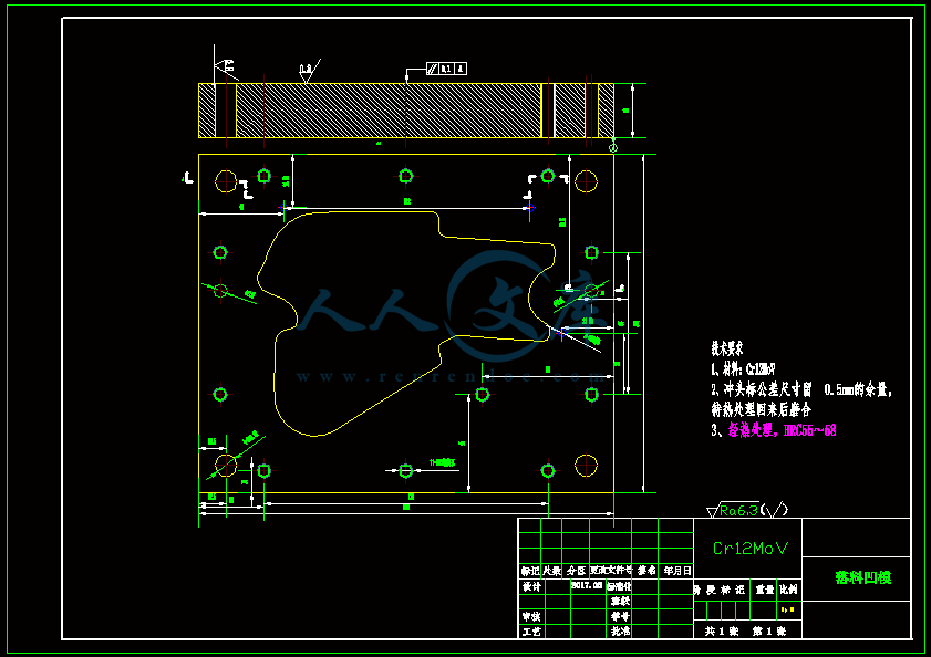
发动机悬置横梁左右、支座冲压模设计【含CAD图纸、说明书】
收藏
资源目录

压缩包内文档预览:(预览前20页/共55页)
编号:14473857
类型:共享资源
大小:14.31MB
格式:ZIP
上传时间:2019-02-08
上传人:机****料
认证信息
个人认证
高**(实名认证)
河南
IP属地:河南
45
积分
- 关 键 词:
-
含CAD图纸、说明书
发动机
悬置
横梁
左右
摆布
支座
冲压
设计
cad
图纸
说明书
仿单
- 资源描述:
-


- 内容简介:
-
毕业设计(论文)任务书 课题名称 发动机悬置横梁左右、支座冲压模设计 学 院专 业 班 级 学 号 姓 名指导教师 教研室主任 院 长 年 2 月20 日 一、课题基本要求:1、学习有关冲压模具的结构和工作原理。2、学习UG或Pro/E软件的三维建模、装配及工程图功能。3、学习Ansys/Modlflow软件的分析功能。4、按给定的要求在UG或Pro/E平台上完成模具的零件、装配以及工程图的设计。二、进度计划与应完成的工作(一)进度计划:1、第一至二周:接受任务书,查阅塑料模具设计的相关资料,学习UG或Pro/E、Ansys、Modlflow等软件的相关功能,为设计作准备;2、第三至四周:翻译一篇与设计相关的英文论文,完成开题报告,确定设计方案; 3、第五至八周:模具设计计算; 4、第九至十三周:完成相关三维模型和工程图纸绘制;5、第十四至十六周:整理编写设计说明书,完成所有设计内容,答辩准备;6、第十八周:答辩,修改毕业设计,归档。(二)应完成的工作:1、完成一副模具的设计; 2、编写设计说明书,字数20000左右,其中包括400字左右的中文摘要,英文摘要应与中文摘要内容完全相同;3、翻译一篇与设计相关的外文资料,字数不少于三千字(附英文原文);4、要求运用计算机辅助设计与绘图,图幅不少于四张A0图纸,三维模型一套;5、查阅与课题相关文献十五篇以上。三、主要参考文献、资料机械设计手册 人民教育出版社模具设计手册 机械工业出版社机械设计 人民教育出版社模具制造工艺及装备 机械工业出版社;模具制造工艺 机械工业出版社模具标准件应用手册 中国模具工业协会标准件委员会肖祥芷,李志刚,李德群.CAD在模具设计中的应用.北京:科学出版社,1993.现代模具技术编委会.汽车覆盖件模具设计与制造.北京:国防工业出版社,1998.郭春生,汤宝骏,孙继明.汽车大型覆盖件模具.北京:国防工业出版社,1993.四、完成期限2017年5月20日(暂定,实际时间以学院安排为准)CIRP年报 - 制造技术65(2016)297-300内容列表在ScienceDirectCIRP年报 - 制造技术单词:h t t p:/ / e e。 e l e e e r e r。 c o m / c i r p / d e f a u l t。萨普AA6061铝合金模锻工艺模的运动控制Hiroshi Utsunomiya(2)*,Koki Tada,Ryo Matsumoto日本大阪大学大学院工学研究科材料与制造科学科2-1山田大夫,大阪府大田565-0871A R T I C L E I N F O关键词:淬火铝烫金A B S T R A C T在可热处理的铝合金的模锻中,坯料保持在高温下以进行固溶处理,然后在冷模之间同时压缩和快速冷却以形成过饱和溶液。这个过程类似于铝合金板的热冲压,然而工件坯料相对较厚,厚度应变较大。虽然提出了在伺服压力机上的滑动运动控制的许多应用,但是作为控制工件的微结构和性质的方法尚未被充分讨论。在AA6061坯料的模锻锻造中,讨论模具速度的影响以获得具有均匀分布的更高硬度。2016 CIRP。1.介绍伺服压力机的金属成型工艺有许多优点1。滑动运动控制用于减少成形负载和机器振动,以及改善成形性和润滑性。最成功的冶金应用是高强度钢板的热冲压。奥氏体通过模具之间的快速冷却而转变成马氏体,即模具淬火,使得在小负荷下制造具有较高强度和较小回弹的产品2,3。由于通过在冷模之间夹持热片来实现快速冷却,因此伺服压力机是期望的机器,因为容易实现冲压之后的夹层。另一个应用是从溶液处理生产超饱和固溶体(S.S.S.S.)的可热处理合金4-6。该方法通过去除再加热工艺,缩短老化持续时间中和加强将应变老化效应,在生产率方面具有优点。然而,由于冷却速率,用于热冲压或模具淬火的工件被限制为薄片或箔。如果模具淬火适用于诸如板,坯料和棒的厚工件,则其可以广泛地用于工业中制造厚而坚固的部件和部件。因此,块状金属的锻造锻造的可行性研究很重要。作者介绍了具有较高热导率的硬质合金工具的模具,并报道了钢坯的模锻锻造是可行的7。发现Al-Mg-Si是用于模锻锻造的优选合金。 16 mm厚的AA6061坯料在模锻锻造中大量减少(高度为50),并确认形成过饱和固溶体8。*通讯作者。电子邮件地址:utsmat.eng.osaka-u.ac.jp(H.宇都宫)。顺便提及,在模锻锻造中,在非常短的时间内一次施加热和冷加工,使得锻造产品的微观结构和性能可能不同于常规产品的。它们应该对模具运动敏感。在本研究中,锻造速度对人工时效前后硬度的影响主要在AA6061合金的模锻锻造工艺中进行了研究。圆柱形坯料用于轴对称分析,但是将来对于工业应用需要具有复杂形状的研究。2.实验2.1。工件圆柱坯料由挤压的Al-Mg-Si合金(A6061-T6)棒加工而成。化学组成为Al-0.9Mg-0.57Si-0.2Fe-0.29Cu-0.09Cr。坯料的直径D0为16mm,高度h0为8mm。2.2。模锻使用450kN伺服压力机(H1F45,Komatsu Ind.Corp。)。模具由硬质合金工具(WC-20质量Co,热导率= 70W m 1 K 1,表面粗糙度Ra = 0.02-0.04mm)制成。它们在干燥条件下使用(无润滑)。首先,将坯料在823K的箱式炉中保持1.8kS进行固溶处理。为了避免在锻造之前用冷模接触而突然温度下降,钢坯由钢丝支撑,如图1所示。将坯料从炉中转移到压机中,并在空气中轻微冷却,直到表面温度变为788K,然后在模具之间锻造。 788 K是该合金的最低固溶处理温度9。坯料高度从8mm压缩至4mm(Dh / h0 = 50),其中三个滑动运动示意性地示于图2。虽然/10.1016/j.cirp.2016.04.132 0007-8506 / 2016 CIRP。H.Utsunomiya et al。 / CIRP Annals - Manufacturing Technology 65(2016)297-300图1实验设置示意图。图3.水淬(WQ),空气冷却(AC)和模锻锻造(DQ)中的测量温度变化。图 2.滑动运动的示意图。规定速度恒定,如图2所示实际速度不完全恒定。平均速度为2.5,7.4和17.4mm / s,使得初始应变速率分别为0.21,0.84和2.52s 1。当上模到达下死点时,停止模运动并将坯料夹持8秒以冷却。在打开模具之后,将锻造的坯料排出并保持在空气中。通过在侧表面的中心焊接的CA热电偶测量整个过程中坯料的温度变化,如图1所示。为了比较,还进行了水淬(WQ)和空气冷却(AC)从没有锻造的溶液处理。2.3。老化处理模具淬火的坯料以及水淬火(WQ)和空气冷却(AC)坯料在448K的硅油浴中老化。老化持续时间为0.25,0.5,1,2,4,8, 16和32小时。这意味着0.9,1.8,3.6,7.2,14.4,28.6,57.6和115.2 ks(kiloseconds)。2.4。硬度试验在坯料的抛光纵截面上沿对称轴测量维氏硬度。在中心区域(距离中间平面250mm内)和表面区域(距离端面250-500mm)中进行压痕。压痕载荷为0.49N(50gf),保持时间为15秒。3.结果3.1。连续冷却变换(CCT)图在模具淬火锻造(DQ),水淬火(WQ)和空气冷却(AC)期间的连续冷却曲线在图3中进行比较。 x轴上的时间t从坯料冷却到788K以下并开始锻造的时刻开始。图中的实线C曲线表示通过商业软件JMatPro(Sente Software Ltd.,UK)预测的在没有变形的情况下的b00 Mg 2 Si相的析出开始。据预测,空气冷却(AC)中的钢坯在30秒后显示沉淀。模具锻造(DQ)和水淬火(WQ)中的所有坯料在10秒内快速冷却至低于323K。即使在最低速度(2.5mm / s)下,在t = 2s之前完成压缩,并且在t = 10s之前完成夹持。在最高速度(17.4mm / s)下,由于100Hz的短采样时间,温度变化显示一些波动。水淬火和模锻中的过饱和固溶体的形成在以前的研究8中通过热分析(TG-DTA)和透射电子显微镜(TEM)证实了17.4mm / s。值得注意的是,锻造速度越快,冷却速率越高。3.2。模锻锻造变形在17.4mm / s的模锻锻造期间,纵向截面上宏观结构的变化示于图3中。从未变形的水冷淬火坯料的图像(图4(a),发现粗颗粒在轴向上伸长,并且表面附近的颗粒尺寸更细。这可能是由于在从挤压棒到圆柱坯的加工过程中引入的应变。在Dh / h0 = 20时中断锻造,并且在图5中对中途变形的坯料进行取样和观察。 4(b)。坯料显示侧表面的滚磨。围绕中间平面的金属主要在径向方向上流动,而粒状纤维在端面下方保持垂直,因此清楚地观察到三角形较少变形区域。这意味着表面附近的冷却速率较高。在50压缩后(图4(c),宏观结构在高度上看起来更不均匀。更清楚地观察到围绕中平面的径向颗粒流。这是由于在锻造期间较少的变形区以及温度梯度。换句话说,变形集中在周围图4.锻造过程中钢坯纵截面的宏观组织变化(v = 17:4 mm = s)。H.Utsunomiya et al。 / CIRP Annals - Manufacturing Technology 65(2016)297-300 299中心温度相对较高,因为表面区域被冷模具更多地冷却。3.3。中心硬度在老化之前和老化后的坯料中心周围的硬度在图5中进行比较。.水淬钢(WQ)和以2.5,7.4和17.4 mm / s锻造的三个DQ钢坯的峰值老化持续时间和峰值硬度分别为57.6,3.6,7.2,7.2 ks和108,126,121,115 HV。所有模锻锻坯显示比水淬钢(WQ)更高的硬度。峰值老化时间从57.6 ks的WQ显着缩短到3.6-7.2 ks的模锻(DQ)。发现在较慢速度锻造的坯料中,不仅析出更快,而且峰值硬度更高。在缓慢锻造的情况下,坯料在锻造期间冷却更长的持续时间。因此,锻造温度较低,使得引入更多的位错,加工硬化较大,应变时效增强。3.4。硬度分布通过高度图3中比较了中心附近和表面附近的硬度。当锻造速度较快时,硬度分布较窄,尽管宏观结构更不均匀,如图6所示表面附近的硬度对锻造速度不敏感,而中心周围的硬度随着锻造速度的降低而增加。因此,慢锻造导致不均匀的硬度分布。假设在慢锻造中,坯料在较低温度下变形,从而在中心周围引入更多的位错。值得注意的是,中心和表面之间的硬度差通过老化而降低,但是硬度都显着增加。3.5。锻造速度对坯料宏观结构的影响在不同速度锻造的坯料的宏观结构在图7中进行比较。最高速度的宏观结构已经在图4(c)中示出。端面下方的区域通过与冷模接触而快速冷却,使得变形不严重。另一方面,中心区域被轴向压缩并且在径向方向上伸长。这种效果在更高的锻造速度下更显着(图4(c),因为坯料在相对较高的温度下被压缩,其中中心和表面之间的温度差较大,使得变形集中在中心附近。图 5.人工老化前后坯料中心的硬度。 图6.中心和表面的硬度作为锻造速度的函数。图7纵向坯料的宏观结构作为锻造速度的函数。4。讨论上述结果表明,模锻锻造坯料的显微组织,硬度和老化行为对伺服压力机上的锻造速度非常敏感。这是因为速度影响锻造过程中的温度变化。然而,仅仅从图3所示的冷却曲线了解该行为是不容易的。因为冷却曲线只是显示按时间顺序的温度变化,不考虑变形。另一方面,应力 - 应变曲线对于讨论材料的机械行为是非常有用的,然而其不包括热效应。在模锻锻造中,坯料立即冷却和锻造,因此需要同时考虑变形(应变),载荷(应力)和温度的所有变化,因为该工艺是真正的热机械处理。应力,应变和温度对锻造持续时间的变化如图8(a)-(c)所示。如图8(a)所示,从初始高度和通过激光位移计在假定均匀变形而不进行滚磨的情况下实验测量的滑动位置计算真应变。发现锻造在2秒内完成。由压缩载荷计算的真应力如图8(b)所示。负载增加,并在夹层之前显示最大值。最大应力随着锻造速度的降低而增加。在锻造更快的情况下,应力消除更大。在锻造过程周围的放大的冷却曲线如图8(c)所示。图9(a) - (c)是基于图8的应变,应力和温度的组合图。常规应力 - 应变曲线如图9(a)所示。真应力对温度的影响如图9(b)所示。这些数字意味着坯料在较慢温度下在较慢锻造的情况下变形。温度对真应变如图9(c)所示。锻造持续时间t被添加在H.Utsunomiya et al。 / CIRP Annals - Manufacturing Technology 65(2016)297-300图 8.(a)应变,(b)应力和(c)温度随时间的变化。图9通过组合数据获得的应力,应变和温度之间的关系如图8所示。图9(b)和(c)的曲线上。如图9(c)所示,可知锻造速度越快,冷却速度越快。然而,如果比较相同应变的温度,当锻造速度更快时温度更高。因此,图9(a)、(b)似乎对图8(c)的结果有争议。这是因为每个应变的冷却速率dT / de不总是与标称冷却速率dT / dt一致。实际变形温度很重要。根据图9(c)所示,如果锻造速度快,则主要在热加工或热加工中施加变形。在这种情况下,即使变形是不均匀的,如图4所示,加工硬化可忽略不计,使得锻造后的硬度分布小。另一方面,如果锻造速度慢,则施加的变形大多是热加工或冷加工,因此加工硬化起重要作用。在这些条件下,温度梯度导致产品中的硬度分布。结果表明,低速淬火锻造使变形温度更低,引入更多的位错和硬化中心区域,然后增加人工老化后由于应变老化的硬度。然而,通过高度的硬度分布更宽。5.结论Al-Mg-Si合金的模锻锻造在具有硬质合金工具WC-Co模具的伺服压力机上进行AA6061圆柱形坯料(直径16mm,高度8mm)。研究了锻造速度对温度变化,变形和老化行为的影响。当锻造速度较慢时,标称冷却速率较低。坯料在较低温度下变形,使得中心附近的硬度较高,并且老化后的硬度也较高。然而通过高硬度分布是广泛的,因为坯料在大的温度梯度下变形。如果控制冶金应用的滑动运动,建议立即考虑应力,应变和温度的变化。除了冷却曲线外,温度 - 应变曲线有助于区分热/热/冷加工以及预测锻造钢坯的显微组织和性能。参考文献1 Osakada K,Mori K,Altan T,Groche P(2011)Mechanical Servo Press Technology for Metal Forming。 CIRP Annals 60:651-672。2 Karbasian H,Tekkaya AE(2010)A Review on Hot Stamping。材料加工技术杂志210:2103-2118。3 Lechler J,Merklein M(2008)Hot Stamping of Ultra High Strength Steels as a Key Technology for Lightweight Construction。 Materials Science and Technology 3:1698-1709。4 Garrett RP,Lin J,Dean TA(2005)Solution Heat Treatment and Cold Die Quenching in Forming AA6xxx Sheet Components:Feasibility Study。高级材料研究6-8:673-680。5 Maeno T,Fujii H,Mori K,Sato M(2010)Control of Slide Motion in Hot Impression Die Forging Alloy Billets Using Servo Press。 Steel Research International 81:354-357。6 Jeon JY,Matsumoto R,Utsunomiya H(2014)使用伺服压力机对AA2024铝合金坯料进行模具淬火的可行性研究。 Advanced Materials Re-search 922:286-291。7 Matsumoto R,Osumi Y,Utsunomiya H(2012)Selective Die Quenching of Hot Forged Steel Product Using High and Low Thermal Conductivity Tools on a Servo Press。国际钢铁研究207-210。 (特别版本)。8 Tada K,Matsumoto R,Utsunomiya H,Watanabe K,Matsuda K(2015)Micro-structure evolution of Al-Mg-Si Aluminum Alloy in Die-Quench Forging Process。日本光金属研究所第128次会议论文集(2015),351-352。9 Microstructure and Properties of Aluminium Alloys,(1991),Japan Institute of Light Metals:477.(日文)。Die motion control for die-quench forging process of AA6061 aluminum alloys Hiroshi Utsunomiya (2)*, Koki Tada, Ryo Matsumoto Division of Materials and Manufacturing Science, Graduate School of Engineering, Osaka University, 2-1 Yamada-oka, Suita, Osaka 565-0871, Japan 1. Introduction Metal forming processes on servo presses have many advan- tages 1. Slide-motion control is used to reduce forming load and machine vibration as well as to improve formability and lubricity. The most successful metallurgical application is hot stamping of high-strength steel sheets. Austenite is transformed into martens- ite by rapid cooling between the dies, i.e., die quenching, so that products with higher strength and less spring back are manu- factured at small load 2,3. As the rapid cooling is achieved by sandwiching a hot sheet between cold dies, a servo press is desirable machine because sandwiching after stamping is readily realized. Another application is a production of super-saturated solid solution (S.S.S.S.) of heat-treatable alloys from solution treatment 46. This process has advantages in productivity by removing reheating process, and in shorter aging duration and in higher strengthening due to strain aging effect. However workpieces for hot stamping or die quenching have been limited to thin sheets or foils because of cooling rate. If die quenching is applicable to thick workpiece such as plates, billets and bars, it could be used widely in industries to manufacture thick and stronger components and parts. Therefore feasibility studies of die-quench forging of bulk metals are important. The authors introduced dies of carbide tool with higher thermal conductivity and reported that die-quench forging of steel billets is feasible 7. It was found that Al-Mg-Si is preferable alloy for die-quench forging. 16 mm-thick AA6061 billets were reduced heavily (50% in height) in die-quench forging and formation of supersaturated solid solution was confi rmed 8. By the way, in die-quench forging, hot, warm and cold workings are applied at once in very short duration so that microstructure and properties of forged products may be different from those of conventional products. They should be sensitive to the die motion. In this study, effects of forging speed on hardness before/after artifi cial aging are investigated fundamentally in die-quench forging process of AA6061 alloy. Cylindrical billets were used for axisymmetric analysis, though studies with complicated shapes are required in future for industrial applications. 2. Experiment 2.1. Workpiece Cylindrical billets were machined from an extruded AlMgSi alloy (A6061-T6) bar. The chemical composition was Al0.9%Mg 0.57%Si0.2%Fe0.29%Cu0.09%Cr. The billet was 16 mm in diameter D0, and 8 mm in height h0. 2.2. Die-quench forging A 450 kN servo press (H1F45, Komatsu Ind. Corp.) was used. The dies were made of carbide tool (WC-20mass%Co, thermal con- ductivity = 70 W m?1K?1, surface roughness Ra= 0.020.04 mm). They were used under dry conditions (without lubrication). First, the billet was held in a box furnace at 823 K for 1.8 ks for solution treatment. In order to avoid sudden temperature drop by touching with cold dies before forging, the billet was supported by steel wires as shown in Fig. 1. The billet was transferred from the furnace to the press, and cooled in air slightly until surface temperature became 788 K, then forged between the dies. 788 K is the lowest solution-treatment temperature for this alloy 9. The billet height was compressed from 8 mm to 4 mm (Dh/h0= 50%) with three slide motions schematically shown in Fig. 2. Although CIRP Annals - Manufacturing Technology 65 (2016) 297300 A R T I C L E I N F O Keywords: Quenching Aluminum Hot stamping A B S T R A C T In die-quench forging of heat-treatable aluminum alloys, a billet is held at high temperature for solution- treatment, then compressed and rapidly cooled simultaneously between cold dies to form supersaturated solution. This process is similar to hot stamping of aluminum alloy sheets, however a workpiece billet is relatively thicker and thickness strain is larger. Although many applications of slide- motion control on a servo press were proposed, it has not been well discussed as a method to control microstructure and properties of the workpiece. In die-quench forging of AA6061 billet, effect of die speed is discussed to achieve higher hardness with uniform distribution. ? 2016 CIRP. * Corresponding author. E-mail address: utsmat.eng.osaka-u.ac.jp (H. Utsunomiya). Contents lists available at ScienceDirect CIRP Annals - Manufacturing Technology journal homepage: /cirp/default.asp /10.1016/j.cirp.2016.04.132 0007-8506/? 2016 CIRP. prescribed speed was constant as seen in Fig. 2, actual speed was not exactly constant. The average speed was 2.5, 7.4 and 17.4 mm/s so that the initial strain rate was 0.21, 0.84 and 2.52 s?1, respectively. When the upper die reached the bottom dead center, the die-motion was stopped and the billet was sandwiched for 8 s for cooling. After opening the dies, the forged billet was ejected and held in air. Temperature change of the billet throughout the process was measured by a CA thermocouple welded at the center on the side surface as shown in Fig. 1. For comparison, water-quenching (WQ) and air-cooling (AC) were also performed from the solution treatment without forging. 2.3. Aging treatment The die-quenched billets as well as the water-quenched (WQ) and the air-cooled (AC) billets were aged in a silicone oil bath at 448 K. Aging duration was 0.25, 0.5, 1, 2, 4, 8, 16 and 32 h. It means 0.9, 1.8, 3.6, 7.2, 14.4, 28.6, 57.6 and 115.2 ks (kiloseconds). 2.4. Hardness test Vickers hardness was measured along the symmetrical axis on polished longitudinal section of the billet. Indentation was conducted in center region (within 250 mm distant from the mid-plane) and in surface region (250500 mm distant from the end surface). The indentation load was 0.49 N (50 gf) and the holding time was 15 s. 3. Results 3.1. Continuous cooling transformation (CCT) diagram Continuous cooling curves during die-quench forging (DQ), water quenching (WQ) and air cooling (AC) are compared in Fig. 3. Time t in x-axis starts from the moment when the billet was cooled below 788 K and the forging started. A solid C curve in the fi gure indicates precipitation start of b00Mg2Si phase in case without deformation, which was predicted by a commercial software JMatPro (Sente Software Ltd., UK). It is predicted that the billet in air cooling (AC) shows precipitation after 30 s. All the billets in die-quench forging (DQ) and that in water quenching (WQ) were quickly cooled to below 323 K within 10 s. Even at the lowest speed (2.5 mm/s), compression was fi nished before t = 2 s, and sandwiching was fi nished before t = 10 s. At the highest speed (17.4 mm/s), temperature change shows some fl uctuations due to short sampling time of 100 Hz. Formation of supersaturated solid solution in the billets water-quenched and die-quench forged at 17.4 mm/s was confi rmed by thermal analysis (TG-DTA) and transmission electron microscopy (TEM) in previous study 8. It is notable that cooling rate is higher when forging speed is faster. 3.2. Deformation in die-quench forging Change in macrostructure on longitudinal section during die- quench forging at 17.4 mm/s is shown in Fig. 4. From the image of the as water-quenched billet without deformation (Fig. 4(a), it is found that coarse grains were elongated in the axial direction and that grains near the surface are fi ner in size. This may be due to strain introduced in machining process from an extruded bar to cylindrical billets. Forging was interrupted at Dh/h0= 20% and a halfway-deformed billet was sampled and observed in Fig. 4(b). The billet shows barreling of side surface. Metal around the mid- plane mainly fl ows in the radial direction, while grain fi bers keep vertical beneath the end surfaces so triangular less-deformation zones are clearly observed. It implies that cooling rate near the surfaces is higher. After 50% compression (Fig. 4(c), macrostruc- ture looks more inhomogeneous through the height. Radial grain fl ow around the mid-plane is more clearly observed. This is due to the less deformation zones as well as temperature gradient during forging. In other words, deformation is concentrated around the Fig. 1. Schematic illustrations of experimental setup. Fig. 2. Schematic illustrations of slide motion. Fig. 3. Measured temperature change in the water quenching (WQ), the air cooling (AC) and the die-quench forging (DQ). Fig. 4. Change in macrostructure on longitudinal section of billet during forging (v 17:4 mm=s). H. Utsunomiya et al. / CIRP Annals - Manufacturing Technology 65 (2016) 297300298 center where temperature is relatively higher because surface regions are more cooled by cold dies. 3.3. Hardness around center Hardness around the center of the billets before aging and that after peak aging are compared in Fig. 5. The peak aging duration and peak hardness of the water-quenched billet (WQ) and the three DQ billets forged at 2.5, 7.4 and 17.4 mm/s are 57.6, 3.6, 7.2, 7.2 ks and 108, 126, 121, 115 HV, respectively. All the die-quench forged billets show higher hardness than the water-quenched billet (WQ). Peak aging time is remarkably shortened from 57.6 ks of WQ to 3.67.2 ks of die-quench forging (DQ). It is found that not only precipitation is faster but also peak hardness is higher in the billets forged with slower speed. In case of slow forging, a billet is cooled for longer duration during forging. Therefore forging temperature is lower so that more dislocations are introduced, work hardening is larger and strain aging is enhanced. 3.4. Hardness distribution through the height Hardness around the center and that near the surfaces are compared in Fig. 6. When forging speed is faster, hardness distribution is narrower although the macrostructure is more inhomogeneous as seen in Fig. 3. Hardness near the surface is not sensitive to the forging speed, while hardness around the center increases with decreasing forging speed. Therefore slow forging results in non-uniform hardness distribution. It is supposed that, in slow forging, the billet is deformed at lower temperature so more dislocations are introduced around the center. It is notable that the hardness difference between center and surface is reduced by aging, although both the hardness increases considerably. 3.5. Effects of forging speed on macrostructure of billet Macrostructures of the billets forged at different speeds are compared in Fig. 7. The macrostructure of the highest speed was already presented in Fig. 4(c). Regions beneath end surfaces are cooled rapidly by contacting with cold dies so that deformation is not severe. On the other hand, central region is compressed axially and elongates in the radial direction. Such effect is more pronounced at higher forging speed (Fig. 4(c), because the billet is compressed at relatively higher temperature where temperature difference between center and surface is larger so that deformation is concentrated around the center. 4. Discussion The above-mentioned results show that microstructure, hardness and aging behavior of die-quench forged billets are very sensitive to forging speed on a servo press. This is because the speed infl uences temperature change during forging. However it is not easy to understand the behavior only from a cooling curve shown in Fig. 3, because cooling curve just show chronological temperature change and deformation is not considered. On the other hand, stress-strain curve is very useful to discuss mechanical behavior of materials, however it does not include thermal effects. In die-quench forging, a billet is cooled and forged at once so simultaneous consideration of all the changes in deformation (strain), load (stress) and temperature is required because this process is real thermo-mechanical treatment. Changes in stress, strain and temperature against forging duration are shown in Fig. 8(a)(c). In Fig. 8(a), true strain is calculated from the initial height and the slide position experi- mentally measured by a laser displacement meter under assump- tion of uniform deformation without barreling. It is found that the forging is completed within 2 s. True stress calculated from compression load is shown in Fig. 8(b). Load increases and shows maximum before sandwiching. Maximum stress increases with decreasing forging speed. Stress relief is greater in case of faster forging. Enlarged cooling curves around the forging process are shown in Fig. 8(c). Fig. 9(a)(c) are combined diagrams of strain, stress and temperature based on Fig. 8. Conventional stress-strain curve is shown in Fig. 9(a). True stress against temperature is shown in Fig. 9(b). These fi gures imply the billet is deformed at lower temperature in case of slower forging. Temperature against true strain is shown in Fig. 9(c). Forging duration t is added on the Fig. 5. Hardness at the center of billet before and after artifi cial aging. Fig. 6. Hardness at the center and surface as a function of forging speed. Fig. 7. Macrostructure on longitudinal billet as a function of forging speed. H. Utsunomiya et al. / CIRP Annals - Manufacturing Technology 65 (2016) 297300 299 curves in Fig. 9(b) and (c). From Fig. 9(c), it is found that cooling rate is higher when forging speed is faster. However, if temperatures at same strain are compared, temperature is higher when forging speed is faster. Therefore the results of Fig. 9(a) and (b) seem to be controversial to the results of Fig. 3 and Fig. 8(c). This is because cooling rate per strain dT/de does not always agree with nominal cooling rate dT/dt. Real deformation temperature is important. According to Fig. 9(c), if forging speed is fast, deformation is applied mostly in hot or warm working. In this case, even deformation is inhomogeneous as seen in Fig. 4, work hardening is negligible so that hardness distribution after forging is small. On the other hand, if forging speed is slow, applied deformation is mostly warm or cold working so work hardening plays an important role. Under these conditions, the temperature gradient results in hardness distribution in products. It is concluded that die-quench forging at slow speed makes deformation temperature lower and introduces more dislocations and hardens central region, then increases hardness after artifi cial aging due to strain aging. However hardness distribution through the height is wider. 5. Conclusion Die-quench forging of AlMgSi alloy AA6061 cylindrical billets (16 mm in diameter and 8 mm in height) has been performed on a servo press with carbide tool WC-Co dies. Effects of forging speed on temperature change, defor
- 温馨提示:
1: 本站所有资源如无特殊说明,都需要本地电脑安装OFFICE2007和PDF阅读器。图纸软件为CAD,CAXA,PROE,UG,SolidWorks等.压缩文件请下载最新的WinRAR软件解压。
2: 本站的文档不包含任何第三方提供的附件图纸等,如果需要附件,请联系上传者。文件的所有权益归上传用户所有。
3.本站RAR压缩包中若带图纸,网页内容里面会有图纸预览,若没有图纸预览就没有图纸。
4. 未经权益所有人同意不得将文件中的内容挪作商业或盈利用途。
5. 人人文库网仅提供信息存储空间,仅对用户上传内容的表现方式做保护处理,对用户上传分享的文档内容本身不做任何修改或编辑,并不能对任何下载内容负责。
6. 下载文件中如有侵权或不适当内容,请与我们联系,我们立即纠正。
7. 本站不保证下载资源的准确性、安全性和完整性, 同时也不承担用户因使用这些下载资源对自己和他人造成任何形式的伤害或损失。

人人文库网所有资源均是用户自行上传分享,仅供网友学习交流,未经上传用户书面授权,请勿作他用。
 川公网安备: 51019002004831号