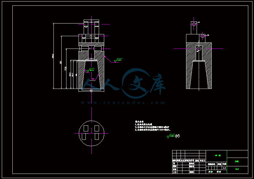
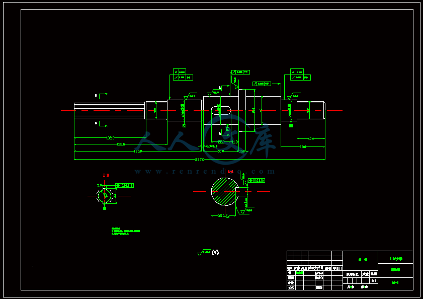
JCS-018A立式加工中心盘式刀库的结构设计【含CAD图纸、说明书】
收藏
资源目录

压缩包内文档预览:(预览前20页/共41页)
编号:17660282
类型:共享资源
大小:5.28MB
格式:ZIP
上传时间:2019-04-13
上传人:机****料
认证信息
个人认证
高**(实名认证)
河南
IP属地:河南
50
积分
- 关 键 词:
-
含CAD图纸、说明书
JCS-018A立式加工中心盘式刀库的结构设计【含CAD图纸、说明书】
- 资源描述:
-


- 内容简介:
-
JCS-018A立式加工中心盘式刀库的结构设计目的和要求1、通过在网上查找资料,理解其结构和工作原理,并以此为模板运用UG设计出加工中心及刀库的机械结构,并且进行运动仿真2、掌握加工中心刀库及其换刀系统的工作原理和设计思路3、通过毕业设计培养综合运用所学的基础理论、基础知识、基本技能和实习内容进行分析和解决问题的能力;使理论与实践紧密的结合主要内容及应完成的工作主要内容: 1了解加工中心刀库及其换刀装置的结构,工作原理2用UG画出各个零件的三维图形3在UG中装配各个零件并进行运动仿真4按要求撰写毕业设计说明书应完成的工作:1、毕业设计任务书2、开题报告3、文献综述4外文翻译5、毕业设计正本(包含毕业设计说明说文本、机械寿命测试台的三维模型、设备动画演示文件、设备的部分零件图纸等)。进度安排2014年1月25日2014年3月10日 完成各种相关资料的查询和收集,学习并且熟练使用UG三维绘图软件。2014年3月11日2014年4月1日 完成设计任务书、开题报告、文献综述、外文翻译等文本的编写和加工中心刀库及其换刀装置结构的认识及各部分尺寸的测量。2014年4月2日2014年5月10日 完成加工中心刀库及其换刀系统的三维建模、运动仿真,编写设计说明书。2014年5月11日2014年5月20日 整理资料,准备答辩。应收集的资料及主要参考文献查阅网上、图书馆的期刊及相关书籍资料共计20余篇。备注注:1、学生进行毕业论文(设计)前,指导教师应填好此任务书,经教研室、部(系)主任签字后,正式给学生下达任务。2、若是课题组共同完成一项大任务应在备注栏内填写同组设计者名单。Virtual automatic tool changer of a machining centre with a real-time simulation Y.H. Jeonga, H. Taeb, B.-K. Mincand D.-W. Chod* aSchool of Mechanical Engineering, Yonsei University, Seoul, 120-749, Korea;bCentral R cSchool of Mechanical Engineering, Yonsei University, Seoul, 120-749, Korea; dDepartment of Mechanical Engineering, Pohang University of Science and Technology, Pohang, Kyungbuk, 790-784, Korea (Received 27 June 2007; fi nal version received 13 November 2007) The discrete systems in a machining centre, such as the automatic tool changer and automatic pallet changer, play important roles in improving productivity in machining automation. However, system confi guration and sequential logic programming still require considerable skill and are handled on a case by case basis. A simulation-based verifi cation environment could improve system performance, reduce ramp-up time and cost, and avoid false setup and system deterioration. In this study, we developed a simulation model as well as a visualisation of a disk-type automatic tool changer (ATC) to assist with ATC mechanical design and PLC logic verifi cation. Our simulation model was based on an object-oriented modelling approach, and consisted of model blocks corresponding to essential components such as the motor, gear set, cam-follower, and proximity sensors. We tested the model in a real-time simulation that used the software component of an actual machine tool controller in the simulation loop to evaluate the real-time calculation performance and the feasibility in a real application such as logic and confi guration verifi cation. The results related to the feed drive motion with limit sensor action in the ATC turret operation showed that our approach was practical and met the real-time requirements. Keywords: automatic tool changer; object-oriented model; logic verifi cation; real-time simulation 1.Introduction Computer numerical control (CNC) machine tools are composed of a variety of complex elements such as the feed drive, spindle, automatic tool changer (ATC), automatic pallet changer (APC), computer numerical controller, and programmable logic controller (PLC). Because of this, the design, construction, and setup is a complex and time-consuming process. A typical machining centre has several essential discrete systems such as the ATC, the APC, and guard doors. These subsystems play important roles in machine tool operations and machining automation. As a result, any performance improvement in the discrete systems can drastically increase the productiv- ity. However, the system confi guration, sequential logic generation, and verifi cation all still require considerable skill and are treated on a case by case basis because the process does not have eff ective verifi cation methods or environments. Simulation techniques have been successfully em- ployed in many industries to improve product quality and reduce development cycle time. In the machine tool industry, many types of simulation such as the fi nite element method (FEM) for machine tool frames, for example, are used in the development and manage- ment of machine tools. In this context, a verifi cation environment based on simulation could improve the system performance, reduce ramp-up time and cost, and avoid false setup and system deterioration. Various approaches are used to control or simulate discrete systems such as production lines. The typical and most prevalent method uses a Petri Net (David and Alla 1994). In an exemplary study, Lee and Hsu (2005) proposed a simplifi ed Petri Net controller, which included sensor status information to simplify process modelling at the controller design level. In their research on the design of ATC mechanisms, Go kler and Koc (1997) designed an automatic disk- type tool changer for a horizontal CNC machining centre, and Dereli and Filiz (2000) proposed a genetic algorithm-based optimisation method for the index position of a cutting tool on an ATC. In addition, Baykasoglu and Dereli (2004) presented a meta- heuristic optimisation system to determine the optimal index position of cutting tools for minimising the indexing time of the tool magazine on a CNC machine tool. While most of the existing research on ATCs has focused on determining the index position on tool magazines, a substantial amount of research has been devotedtomachinetoolsimulationandvirtual machinetools.ErkorkmazandAltintas(2001) *Corresponding author. Email: dwchopostech.ac.kr International Journal of Computer Integrated Manufacturing Vol. 21, No. 8, December 2008, 885894 ISSN 0951-192X print/ISSN 1362-3052 online ? 2008 Taylor these intercommunicate through shared memory. The controller library was composed of a numerical control (NC) kernel to control the feed drive system and a PLC kernel for operation of the discrete systems such as the limit sensor and ATC turret. The simulation model included the feed drive andATC turret modelsdescribed in section 3. We monitored the simulation results using a separate computer to avoid aff ecting the real-time performance ofthecomputerrunningthesimulationloop. The connection between the controller software and the simulationmodelwasidenticaltothatbetween the controller and the actual feed drive in the ATC turret except that the actual wiring was replaced by internal data communication. The proposed simula- tion was conducted on an industrial personal computer (NI PXI-8186 RT) with real-time kernel, a 2.2 GHz Pentium 4 CPU, and 512 MB of random access memory. We used a fourth-order RungeKutta algo- rithm with an integration time step of 0.5 ms for the simulation. The controller update time was set to 1 ms for the feed drive and 4 ms for the ATC turret. Figures 11(a) and (b) show the user interface of the real-time simulation for the feed drive system with a limit sensor and the ATC turret, respectively. Figure 10.Schematic diagram of a real-time simulation. Figure 11.Real-time simulation environment. 892Y.H. Jeong et al. In Figure 11(a), the feed drive motion is stopped by the action of a limit sensor located at a position of 0.5 m from the origin. The actual calculation time for 0.922 s of motion was 0.030 s, corresponding to better than 3000% of the real-time speed when synchronisation with an actual time base was disabled. In the ATC turret simulation, the PLC logic operates the ATC turret model using the sensor signals just as an actual PLC does. Figure 11(b) shows a snapshot during the simulation. When synchronisation with an actual time base was disabled, the actual calculation time of ATC turret operation during 0.241 s of motion was 0.0046 s, which corresponded to better than 5200% of the real- time speed. Wedesignedathree-dimensionalvisualisation moduletovisualizethesimulationresults. Figures 12(a) and (b) show the visualisation module consisting of a three-axis feed stage, a simple turret magazine, and a status board. The turret magazine showninthe fi gurehas14pallets.Thesignal board shows the sensor and operational status such as over-travel, current tool number, proximity sensor outputs, and homing results, i.e. typical discrete system information. 5.Conclusions In this study, we developed a simulation model of an automatic tool changer using a turret magazine. We used an object-oriented method to build a generalised model in which the essential components of the ATC turret were modelled as individual blocks, and then connected together as they would be in an actual ATC. Each block had its own parameters and equations that kinematically described the motion of the correspond- ing block. Thesimulationresultsdemonstratedthatthe proposed method generated realistic operations for component motions and sensor signals. We developed a three-dimensional visualisation to demonstrate the simulation results. The integration of our simulation model with the actual machine tool controller showed that our model could be used for the real-time logic verifi cation to reduce ramp-up time and false setup problems. In the real-time simulation of the PLC logic, the model successfully played the role of the real ATC turret and feed drive. We demonstrated that our models could satisfy real-time requirements, and the calculation time was less than 1/30th of the simulation loop time. Acknowledgement This study was supported by grant no. KRF-2004-202- D00068 from the Ministry of Science and Technology. References Baykasoglu, A. and Dereli, T., 2004. Heuristic optimization system for the determination on index positions on CNC magazines with the consideration of cutting tool duplica- tions. International Journal of Production Research, 42 (7), 12811303. Bru ck, D., et al., 2002. Dymola for multi-engineering modeling and simulation. In: 2nd International Modelica Conference, 55.155.8. David, R. and Alla, H., 1994. Petri nets for modeling of dynamic systemsa survey. Automatica, 30 (2), 175202. Dereli, T. and Filiz, _I.H., 2000. Allocating optimal index positions on tool magazines using genetic algorithm. Robotics and Autonomous Systems, 33, 155167. Erkorkmaz, K. and Altintas, Y., 2001. High speed CNC system design. Part II: modeling and identifi cation of feed drives. International Journal of Machine Tools and Manufacture, 41, 14871509. Go kler, M.L. and Koc , M.B., 1997. Design of an automatic tool changer with disc magazine for a CNC horizontal machining center. International Journal of Machine Tools and Manufacture, 37 (3), 277286. Figure 12.Visualisation module for the simulation results. International Journal of Computer Integrated Manufacturing893 Harrison,R.,West,A.A.,andWright,C.D.,2000. Integrating machine design and control. International Journal of Computer Iintegrated Manufacturing, 13 (6), 498516. Hussein, B.A., 1998. A systematic approach for modelling mechatronics systems. CIRP Annals, 48 (1), 431436. Jeong, Y.H., Min, B.-K., and Cho, D.-W., 2006. Estimation of machine tool feed drive inclination from current measurements and a mathematical model. International Journal of Machine Tools and Manufacture, 46, 1343 1349. Lee, J.-S. and Hsu, P.-L., 2005. A systematic approach for the sequence controller design in manufacturing systems. International Journal of Advanced Manufacturing Tech- nology, 25, 754760. Sheu, J.J. and Fu, T.C., 2006. Development of an intelligent virtual reality system for high speed machining. Materials Science Forum, 505507, 626630. Suh, S.-H., et al., 2003. Modelling and implementation of Internet-based virtual machine tools. International Jour- nal of Advanced Manufacturing Technology, 21, 516522. 894Y.H. Jeong et al. 国家计算机集成制造杂志卷21,8号,2008十二月,885894一个实时仿真虚拟加工中心自动换刀装置Y.H. Jeong H. Tae, B.-K. Minand D.-W. Cho*School of Mechanical Engineering, Yonsei University, Seoul, 120-749, Korea;Central R&D Center, MANDO Corporation,Yongin-Si, Kyonggi-Do, 446-901, Korea;School of Mechanical Engineering, Yonsei University, Seoul, 120-749, Korea;Department of Mechanical Engineering, Pohang University of Science and Technology, Pohang, Kyungbuk, 790-784, Korea(Received 27 June 2007; nal version received 13 November 2007)在加工中心的离散系统,如自动换刀装置和托盘自动交换装置在提高加工自动化生产中扮演着重要的角色。然而,系统配置和时序逻辑编程仍需要相当大的技能和基础上,根据实际情况处理。基于仿真的验证环境可以改善系统性能,减少过渡时间和成本,避免错误的设置和系统。在这项研究中,我们开发了一个仿真模型以及盘式自动换工具的可视化与空中交通管制(ATC)协助机械设计和PLC逻辑验证。我们的仿真模型是基于面向对象的建模方法,并由模型块对应的基本组件(如电机、齿轮组、等),功能和接近传感器。我们测试了在实时仿真模型,使用一个实际的机床控制器的软件组件的仿真循环评估实时计算性能和可行性在真实的应用程序中,如逻辑和配置验证。相关结果提要驱动运动在ATC炮塔操作限制传感器行动表明,我们的方法是实用和满足实时要求。关键词:自动工具改变;面向对象模型;逻辑验证;实时仿真1. 介绍 计算机数控(CNC)机床是由各种复杂的元素,比如提要驱动主轴,工具自动更换装置(ATC),自动托盘商(APC),计算机数字控制器和可编程序逻辑控制器(PLC)。因此,设计、构建和安装是一个复杂和耗时的过程。 一个典型的加工中心有几个重要的离散系统,如空中交通管制,APC,守卫大门。这些子系统扮演了一个重要的角色在机床操作和加工自动化。因此,任何性能改进的离散系统可以大大提高生产率。然而,系统配置、时序逻辑生成和验证所有仍然需要大量的技巧和治疗基础上,根据实际情况,因为这个过程没有有效的验证方法或环境。 仿真技术已经成功地使用在许多行业提高产品质量和减少开发周期时间。在机床行业,许多类型的模拟等机床有限元方法(FEM)框架,例如,用于机床的开发和管理。在这种背景下,基于仿真验证环境可以提高系统性能,减少走弯路和成本,避免错误的设置和系统恶化。 各种方法用于控制或模拟离散系统,如生产线。典型的和最普遍的方法使用佩特里网(大卫和真主安拉1994)。在一个模范的研究中,李和许(2005)提出了一个简化的佩特里网控制器,其中包括传感器状态信息来简化控制器设计层面的过程建模。在ATC的设计机制,研究Gokler和Koc(1997)设计了一个自动盘式工具改变卧式数控加工中心,和Dereli Filiz(2000)提出了一种遗传算法优化方法指数一个空中交通管制的刀具的位置。此外,Baykasoglu和Dereli(2004)提出了一个meta-heuristic优化系统来确定刀具的最佳索引位置最小化theindexing时间数控机床工具的杂志。 一个验证开发的饲料与摩擦传动系统的动态模型表示为Stribeck曲线,并确定了系统参数使用最小二乘法和卡尔曼滤波。书钉et al。(2003)介绍了一个基于互联网的虚拟机工具使用机械部件的运动链数控和计算机辅助设计和制造(CAD / CAM)用于教育目的。张文雄和傅(2006)还开发出一种虚拟机工具培训以及网络制造控制。重要的是,他们的系统包括一个切削力预测模块基于人工神经网络(ANN)。侯赛因(1998)提出了一个统一的方法对机电一体化系统模型使用多维数组和映射函数作为造型方案,虽然Harrison et al.。(2000)介绍了一个集成的机械设计和控制环境,可以应用于机械设计,控制和维护。哈里森et al。(2000)应用的逻辑设计和快速成型部分的环境他们设计开发饮料can-body制造机器。 然而,尽管大量的研究机床的模拟和离散系统,很难找到一个ATC系统仿真方法,减少机床开发成本和减轻PLC逻辑生成和验证的难度和复杂性。此外,现有的离散系统的仿真研究考虑系统作为一个简单的序列或数据流,而忽略机械运动学或动力学等特点。因此,它已经很难包含系统的运动学或动力学行为或部分在系统级模拟。 本研究的目的是开发一个仿真模型,可以应用到ATC的空中交通管制机制设计和PLC逻辑验证。目标特性的仿真模型,该模型必须是通用的,是可重用的扩展成各种ATC类型,并且模型必须准确地描述传感器信号和部分运动运动,这样他们就可以被应用到各种应用程序。在这种背景下,我们开发了以下模型的策略。我们使用了一个基于组件的方法提高通用性。这意味着组件模型块被定义为可更换单元所购买机床建设者。每个模型块有自己的参数,有关其运动方程,并定义输入和输出信号描述模型之间的连接块。商业化或标准化的造型语言和工具被用来确保兼容性等各种机床的开发流程设计、优化和验证逻辑,和维护过程。 我们描述一个典型的盘式ATC机制,在第二节的基本组件。第三节讨论了ATC仿真模型的细节我们发达的模型块对应的基本部分。第四节描述了两个仿真结果,介绍了实时仿真方法和仿真结果可视化模块。第一个模拟与提要驱动器与极限运动传感器模拟工具改变位置的方法。第二个是ATC炮塔工具变化的模拟操作。我们使用我们的实时仿真方法结合仿真模型与实际机床控制器的软件组件在一个模拟循环使用内部数据通信表明,我们的模型实时计算性能和PLC逻辑验证是可行的。结论在第五节。图1 原理图的一个典型的盘式ATC没有改变图2 等效的模型等。图3 简化的快动作开关用作限制传感器。图4 接近传感器的等效模型和遥感磁盘和螺栓。2。调查的ATC模型杂志典型的盘式ATC装置包含以下基本组件:一个炮塔磁盘,一组齿轮、回转马达、等功能,和几个传感器。回转马达,它提供了驱动功率的ATC炮塔装置等轴旋转,间歇旋转等变化连续动作,从垂直旋转轴方向横向。它使用的组合凸轮和磁盘索引,转移其旋转运动通过其轴等功能的装置。最后,齿轮装置和磁盘旋转速度剖面,可以简化低速度值为零的矩形波。注意,本研究中使用的盘式ATC装置有两个类型的接近传感器,使用磁盘和螺栓检测工具改变位置和计算炮塔旋转间隔。图1显示了一个示意图的互连基本组件在一个典型的盘式ATC装置。在本研究中,我们模拟限制传感器模拟自动工具的复杂连续的运动变化,包括炮塔装置的驱动和运动。图5 仿真模型的一个提要积极限制传感器驱动系统。图6 一个提要驱动系统的仿真结果积极限制传感器。图7 ATC炮塔的仿真模型。4。模拟的自动工具改变本研究构建的仿真模型使用基于Modelica Dymola语言(勃拉克et al . 2002年)。模型的仿真模型由组件(如电机、齿轮的集合(齿轮箱))等对应的功能。每个模型块标准形式,其中包括输入和输出信号,模型参数,和自己的方程式。该模型结构容易实现Modelica语言,因为语言是面向对象的。模型的每个部分的属性等参数和方程可以指定和修改使用图形框图界面或在一个文本文件中。模拟的操作限制传感器在旋转电机驱动的线性阶段,我们联合动态仿真模型的线性阶段从先前的工作(Jeong et al . 2006年)限制传感器模型,如图3所示。图5显示了总体仿真模块,该模块可用于遥感超程阶段归航,到达的位置工具改变操作。在这项研究中所使用的线性阶段模型由模型块对应的速度和转矩控制,一个简单的直流电机,轴向联合、导螺杆和导轨。积极的限制传感器响应瞬时表位置。的图中显示积极限制传感器监控表的位置。因此,饲料的表位置获得或预测转移到限制传感器块驱动仿真模型,方程(5)所示。限制传感器模型块比较转移位置指定的限制传感器位置。图6显示了模拟线性阶段,传感器操作控制电机速度时60 rad / s。图6(a)显示了电机速度和驱动电流、和图6(b)显示了表和传感器位置。注意,传感器输出从0变为1当表到达0.1米。传感器的传感器位置公差模型中被设置为0。图8 ATC炮塔操作的仿真结果。我们使用我们的ATC炮塔模型模拟ATC炮塔的性能。图7显示了ATC炮塔的实际仿真模型和恒定的命令。这表明两个接近传感器分别检测螺栓和连接到炮塔磁盘。仿真模型显示当前工具数量随着炮塔角度变化。此外,两个距离传感器的输出信号监测的PLC内核提供CNC控制器,控制ATC炮塔操作。仿真中使用的模型参数如表1所示,从改造小型加工中心(SPT-V30T,现代汽车(Hyundai Motor Co。)和一个炮塔类型overhead-disk杂志和一个基于PC的数控(HX TurboTek)。十四个工具装置。图8(a)、(b)和(c)显示仿真结果当工具改变从1号到12号。更具体地说,图8(一个)显示炮塔的旋转角,不断旋转的动作等功能。图8(b)和(c)显示的逻辑输出接近传感器连接到磁盘和等轴炮塔。从这些数据中我们可以看到接近传感器的输出的炮塔磁盘是相反的,接近传感器等因为等对应的旋转炮塔的旋转磁盘。我们比较仿真结果与实际行动炮塔运动。图9显示了这种比较的结果变化时间从第一个工具(工具1)到最后一个工具。仿真结果在2%的实际时间。我们推断这个错误来自实际电
- 温馨提示:
1: 本站所有资源如无特殊说明,都需要本地电脑安装OFFICE2007和PDF阅读器。图纸软件为CAD,CAXA,PROE,UG,SolidWorks等.压缩文件请下载最新的WinRAR软件解压。
2: 本站的文档不包含任何第三方提供的附件图纸等,如果需要附件,请联系上传者。文件的所有权益归上传用户所有。
3.本站RAR压缩包中若带图纸,网页内容里面会有图纸预览,若没有图纸预览就没有图纸。
4. 未经权益所有人同意不得将文件中的内容挪作商业或盈利用途。
5. 人人文库网仅提供信息存储空间,仅对用户上传内容的表现方式做保护处理,对用户上传分享的文档内容本身不做任何修改或编辑,并不能对任何下载内容负责。
6. 下载文件中如有侵权或不适当内容,请与我们联系,我们立即纠正。
7. 本站不保证下载资源的准确性、安全性和完整性, 同时也不承担用户因使用这些下载资源对自己和他人造成任何形式的伤害或损失。

人人文库网所有资源均是用户自行上传分享,仅供网友学习交流,未经上传用户书面授权,请勿作他用。
 川公网安备: 51019002004831号