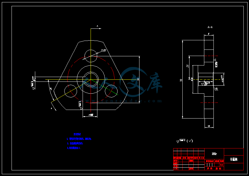
履带机器人驱动机构及关节机构设计【救灾机器人】【含CAD图纸、说明书】
收藏
资源目录

压缩包内文档预览:
编号:17668362
类型:共享资源
大小:1.19MB
格式:ZIP
上传时间:2019-04-13
上传人:机****料
认证信息
个人认证
高**(实名认证)
河南
IP属地:河南
50
积分
- 关 键 词:
-
救灾机器人
含CAD图纸、说明书
CAD图纸和
含CAD图纸
CAD图纸和说明书
驱动机构设计
CAD图纸和说明书
CAD 图纸和说明书
CAD图纸
履带驱动机构
机器人驱动及
- 资源描述:
-


- 内容简介:
-
英文文献翻译学 生 姓 名:学 院:专业及班级:学 号:指 导 教 师:Simple structure pipe inspection robotThis article describes the architecture of the original pipe inspection robot. The robot contains two universal joints by the hinge portion. Part of the parallel movement along the pipeline axis wheel drive, while the other part is forced to follow the axis of rotation of the wheel and the inclined pipe spiral motion related. A single motor is placed between the two institutions motion generated. All wheels mounted on the suspension, in order to adapt to changing curve pipe. The robot has its own battery and a wireless link. Four different diameters respectively of 170,70 and 40 mm. For smaller diameters, battery, radio receiver can be placed in any extra bodies. This architecture is very simple, its rotational motion can be used to scrub or inspection tasks.Keywords: autonomous mobile robot in pipeline inspection, spiral motionPipeline inspection robot has been studied for a long time, many of the original motion ideas have been proposed to solve the many technical difficulties in pipe diameter, curve and change-related energy supply. Although an exhaustive review of the literature is impossible, according to the limited space available, several major categories can be identified several broad categories:1 For a small number of projects to follow the earthworm principles: the central part axial movement, and both ends of the connected equipment with barrier pipes. This concept has been proposed pneumatic version,But they need the power cord. For smaller diameter (10 mm or less), according to the principle of inchworm, or driven by a sawtooth voltage based on inertial motion, or in combination with the differential coefficient of friction vibration fin, the piezoelectric drive.2 For a variety of medium-sized pipes, depending on the diameter of adaptability and cornering ability classical electromechanical systems have been proposed various structures involved in the wheel tracks and kinematics.3 For large pipes, pipe crawling walk has also been proposed.Four mobile robot proposed in this paper belongs to the second category, the liquidity of their tube diameter from 40 to 170mm, the design attempts to use a single drive to reduce the complexity of the realization of the machine along the tube, even though our research efforts can be seen as an independent to result. But this spiral theory seems to have been studied.The robot is divided into two parts, the stator and rotor, including a DC connection, motor and gearhead, universal joints. The stator is equipped with a set of wheels to help movement parallel; in this case, the constraint along the tube axis of the stator, the rotor wheel only along the helical path, the axial velocity and the relationship between the rotational speed of the robotWherein R is the pipe radius, a is the inclination angle of the wheel. Stator and rotor must ensure stability, to ensure that the pipeline and sufficient contact force between the robot to adapt to changes and obstacles pipe diameter and allows travel in a curved pipe. For larger robot (D -170), the robot is rigidly connected to the motor shaft to ensure stability. For smaller diameter, bend the need for greater freedom, requires twice the number of wheels.Diameter of 70 mm or more robots provide nine cells, located in the stator. Tests showed that the smaller diameter, this configuration is not possible. First by the rotor, and the second one includes a motor and gear, and the third is the stator wheel to the axle, energy supply and telecommunications networks. Two schemes were investigated 70mm diameter. In the first, a motor and a battery mounted on the stator, but can not be used in the second scenario, if the robot using a power cable.中文翻译:简单结构管道检测机器人本文介绍了管道检测机器人的原始架构。该机器人由包含两个万向节铰接部分。一部分是沿管道平行移动的轴车轮盘,而另一部分则是被迫遵循与螺旋运动有关的轴线旋转的车轮倾斜管。单台电动机被放置在两个机构之间产生的运动。所有车轮安装在悬架上,以适应不断变化的曲线管道。该机器人有其自己的电池和无线链路。四种不同管径分别为的170,70和40毫米。对于较小的直径,电池,无线电接收器,可放置在其他额外的机构中。这种架构非常简单,其旋转运动可以被利用来进行擦洗或检验任务。关键词:自主移动机器人,在管道检测,螺旋运动管道检测机器人已经被研究了很长一段时间,许多原来的运动观念被提出来解决在管道直径,曲线和能源供应变化中有关的许多技术困难。虽然一个详尽的文献回顾是不可能的,根据有限的可用空间,几大类别,可确定几大类别:1对于小规模,许多项目遵循蚯蚓原则:中央部分组成轴向移动,而两端连接的设备具有阻隔管道。这一概念已经提出气动版本,但他们需要电力脐带。对于较小的直径(10毫米或更小),根据尺蠖的原则,或根据惯性运动由锯齿波电压驱动,或使用与微分摩擦系数振动鳍,则采用压电驱动。2对于各种中型管道,根据直径的适应性和转弯能力古典机电系统已提出各种涉及车轮和轨道运动学结构。3对于大型管道,管道爬行走路也已提出。文中提出的四个移动机器人属于第二类,他们的管直径从40到170mm,该设计尝试使用单一驱动器减少机器的复杂性实现沿管的的流动性,即使我们的研究可看作一个独立努力地结果。但此螺旋论似乎已经被研究过。该机器人主要分为两部分,定子和转子,包括一个DC连接,马达与减速机,万向节。定子配备了一套轮子,有助于运动平行; 在这种情形下,定子约束沿着管轴,而转子的车轮只能沿着螺旋轨迹,该机器人之间的轴向速度和旋转速度的关系 。其中R为管道半径, a是车轮倾斜角度。定子和转子必须保证稳定性,以保证机器人之间的管道和足够的接触力,以适应管道直径的变化和障
- 温馨提示:
1: 本站所有资源如无特殊说明,都需要本地电脑安装OFFICE2007和PDF阅读器。图纸软件为CAD,CAXA,PROE,UG,SolidWorks等.压缩文件请下载最新的WinRAR软件解压。
2: 本站的文档不包含任何第三方提供的附件图纸等,如果需要附件,请联系上传者。文件的所有权益归上传用户所有。
3.本站RAR压缩包中若带图纸,网页内容里面会有图纸预览,若没有图纸预览就没有图纸。
4. 未经权益所有人同意不得将文件中的内容挪作商业或盈利用途。
5. 人人文库网仅提供信息存储空间,仅对用户上传内容的表现方式做保护处理,对用户上传分享的文档内容本身不做任何修改或编辑,并不能对任何下载内容负责。
6. 下载文件中如有侵权或不适当内容,请与我们联系,我们立即纠正。
7. 本站不保证下载资源的准确性、安全性和完整性, 同时也不承担用户因使用这些下载资源对自己和他人造成任何形式的伤害或损失。

人人文库网所有资源均是用户自行上传分享,仅供网友学习交流,未经上传用户书面授权,请勿作他用。
 川公网安备: 51019002004831号