轮式移动提升机构设计【含CAD图纸、说明书、三维图纸】
收藏
资源目录

压缩包内文档预览:
编号:22883914
类型:共享资源
大小:59.17MB
格式:ZIP
上传时间:2019-11-03
上传人:机****料
认证信息
个人认证
高**(实名认证)
河南
IP属地:河南
50
积分
- 关 键 词:
-
含CAD图纸、说明书、三维图纸
轮式
移动
提升
机构
设计
CAD
图纸
说明书
三维
- 资源描述:
-
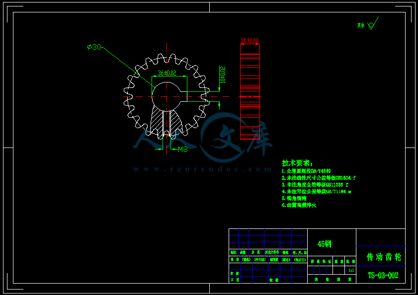
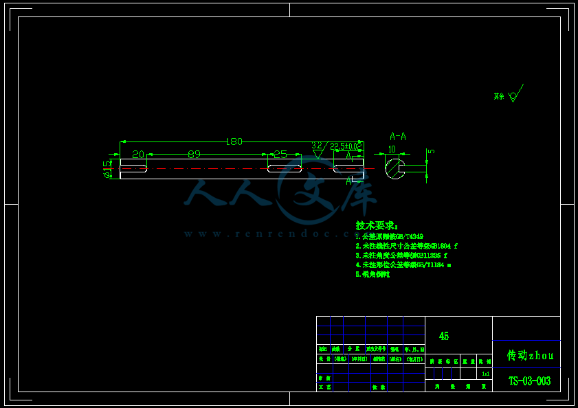
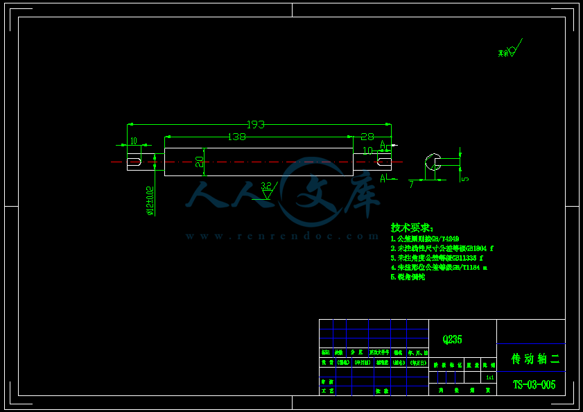
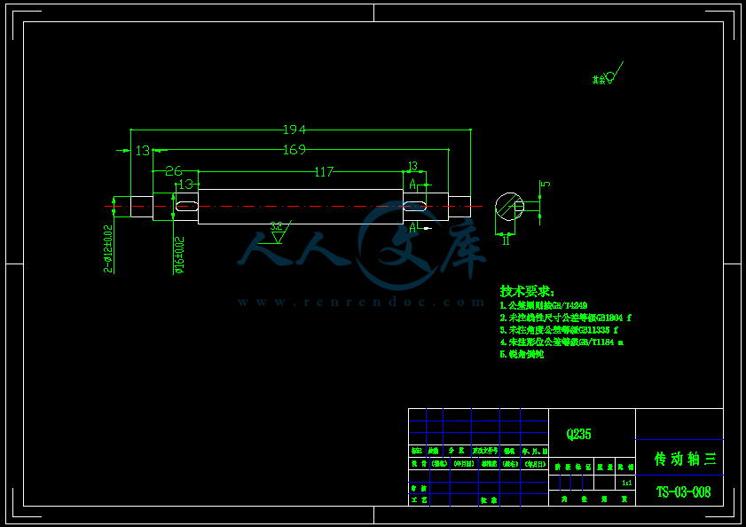
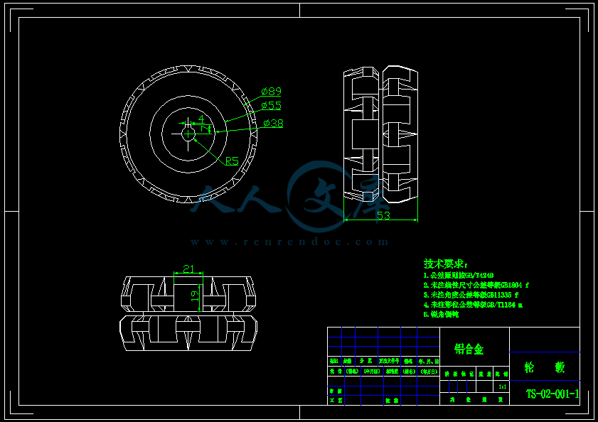
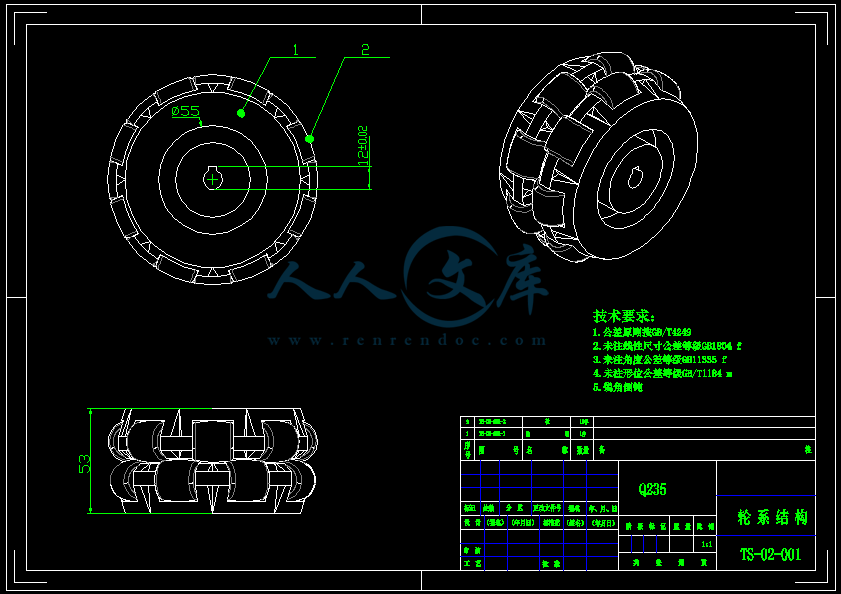
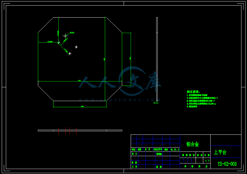
【温馨提示】压缩包内含CAD图有下方大图片预览,下拉即可直观呈现眼前查看、尽收眼底纵观。打包内容里dwg后缀的文件为CAD图,可编辑,无水印,高清图,压缩包内文档可直接点开预览,需要原稿请自助充值下载,所见才能所得,请见压缩包内的文件及下方预览,请细心查看有疑问可以咨询QQ:11970985或197216396

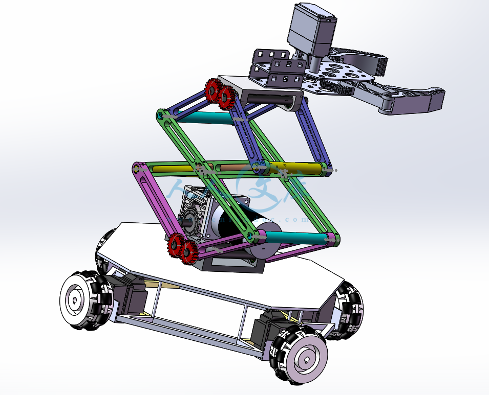
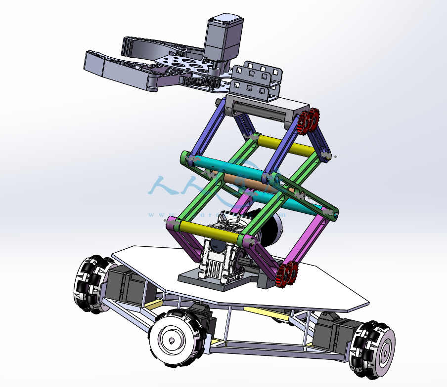
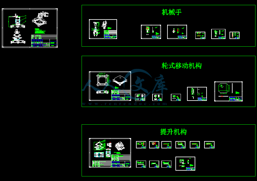
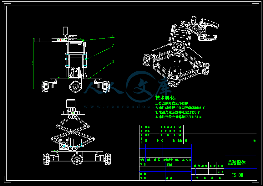
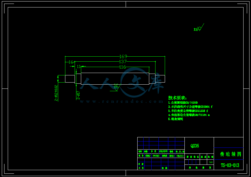
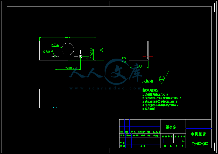
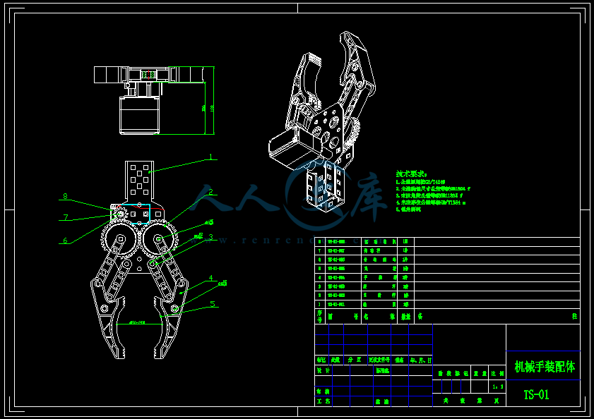
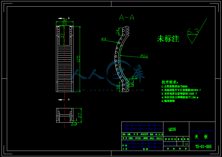
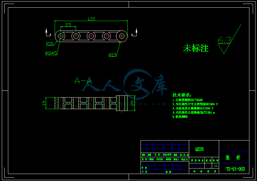
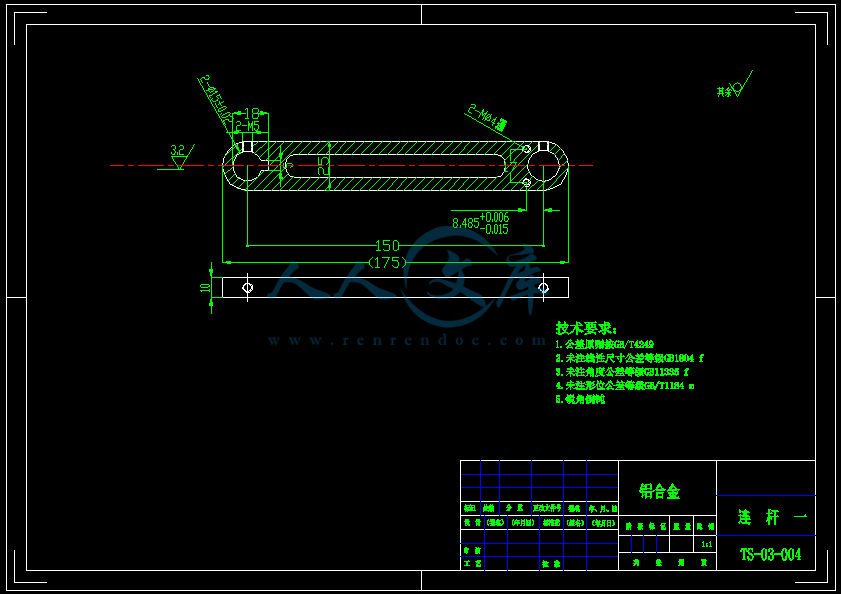
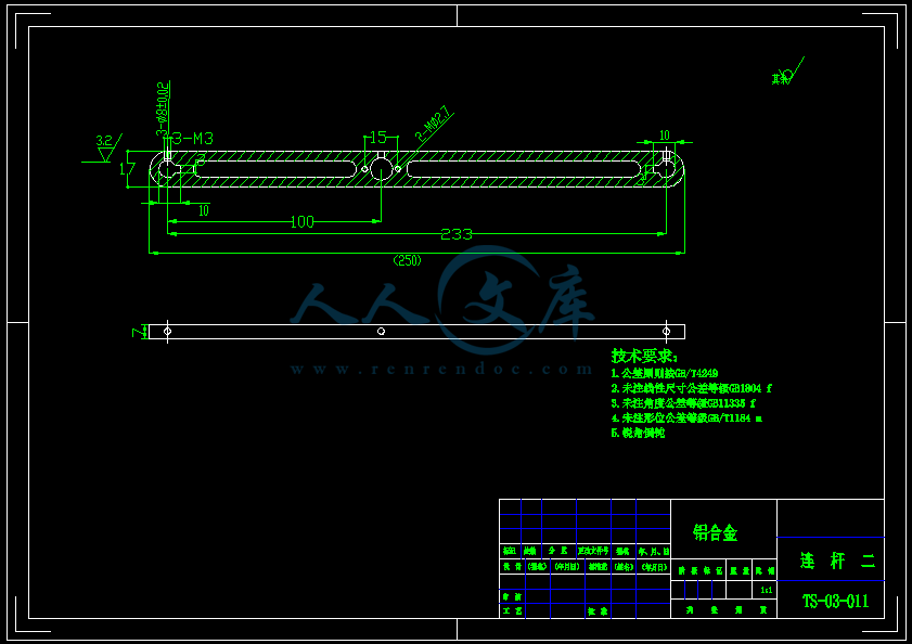
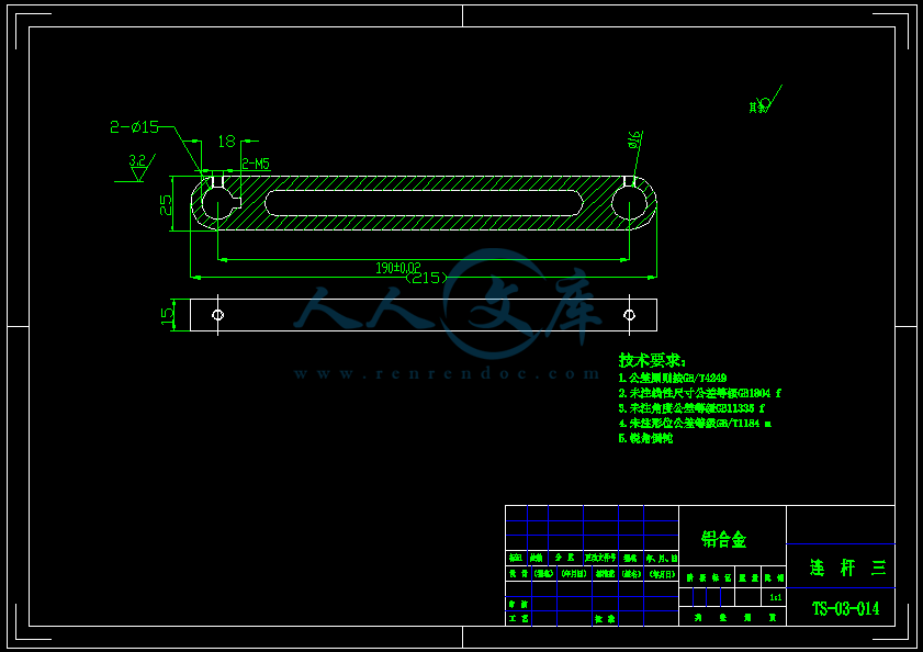
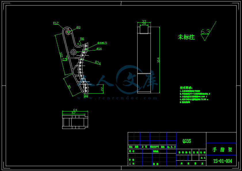
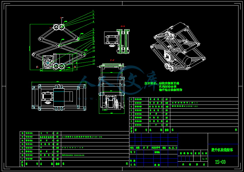
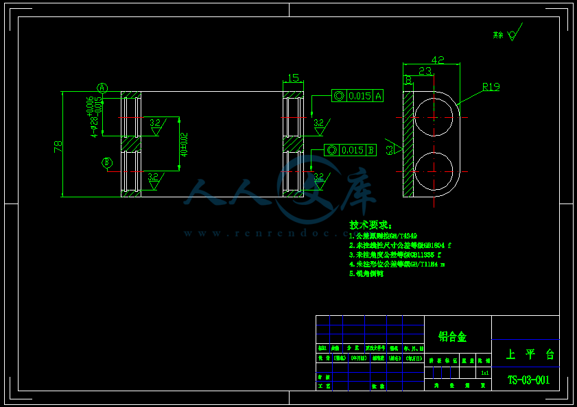
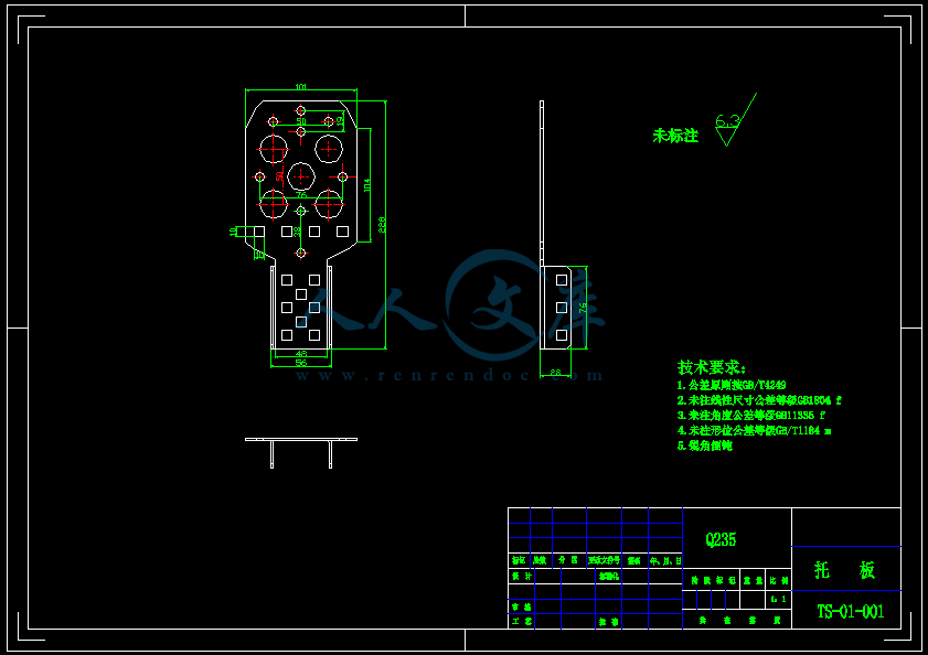
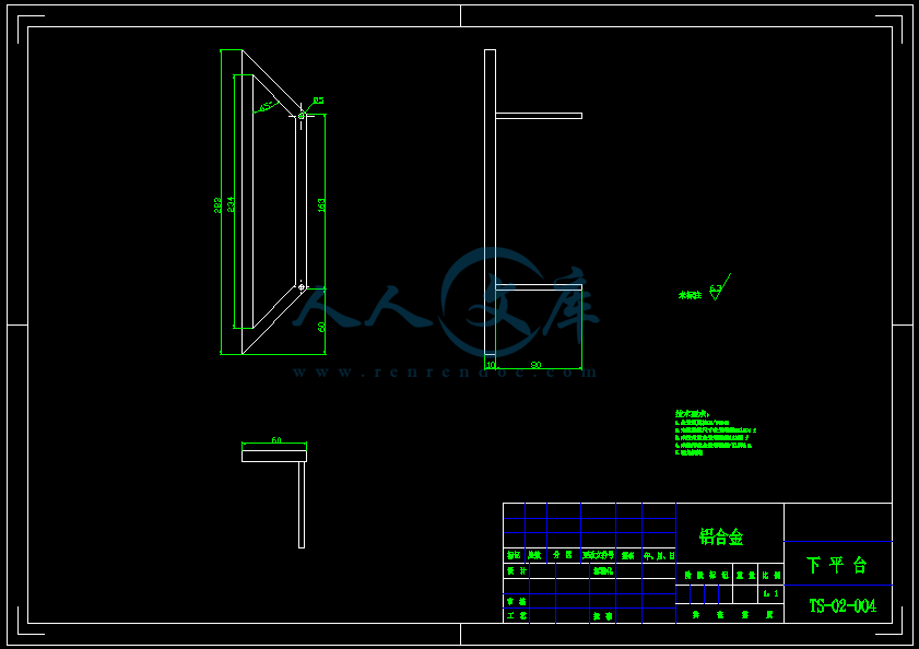
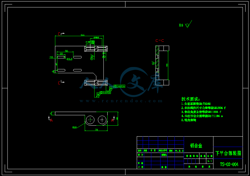
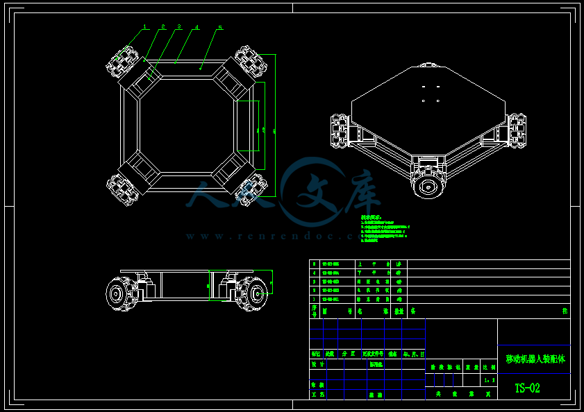
- 内容简介:
-
Mesh Preparation: 0 hr 0 min 0 secStandard solid mesh bolt head imprint and hard point processing: 0 hr 0 min 0 secStandard solid mesh total preparation including imprint: 0 hr 0 min 0 secStandard surface meshing for Solid Mesh: 0 hr 0 min 1 secStandard volume meshing for Solid Mesh: 0 hr 0 min 0 secStandard solid mesh arranging data: 0 hr 0 min 0 secStandard solid mesh total: 0 hr 0 min 1 secBeam mesh: 0 hr 0 min 0 secPreparing to transfer data: 0 hr 0 min 2 secProcessing material properties: 0 hr 0 min 0 secProcessing element groups: 0 hr 0 min 0 secProcessing drop test gap nodes: 0 hr 0 min 0 secUpdating thickness for shell regions: 0 hr 0 min 0 secProcessing rconst for elements: 0 hr 0 min 0 secProcessing egroups: 0 hr 0 min 0 secTransferring loads and boundary conditions: 0 hr 0 min 0 secGenerating body pairs to check contact: 0 hr 0 min 0 secGenerating contacts: 0 hr 0 min 0 secNumber of Contacts: 0Transfer SL1 data: 0 hr 0 min 0 secGenerate more accurate contact data: 0 hr 0 min 0 secNumber of contact data: 0Transfer beam/joint contact data: 0 hr 0 min 0 secTransferring other special loads: 0 hr 0 min 0 secTransferring bearing loads: 0 hr 0 min 0 secTransferring mass elements: 0 hr 0 min 0 secTransferring point loads: 0 hr 0 min 0 secTransferring distributed beam loads: 0 hr 0 min 0 secTransferring rigid bodies: 0 hr 0 min 0 secTransferring component no penetration: 0 hr 0 min 0 secWriting Data: 0 hr 0 min 0 secTransferring analysis options: 0 hr 0 min 0 secTotal midsurf mapping: 0 hr 0 min 0 sec压缩包内含有CAD图纸和说明书,咨询Q 197216396 或 11970985摘要随着现代工业的快速发展,以互联网为媒介向四周扩散的贸易模式逐渐成为主流形式,正因为互联网行业的快速发展,也促使了周边产业的进步。其中离我们最近的一个产业当属物流行业。以往物流行业只针对于大型货品的长途运输, 但是自从有了新的商业模式,物流行业新加了小产品;近距离;快速等属性。本次我们课题做的设备是针对于物流的仓储分拣环节而做的专用设备。移动提升机构能够很大程度上的提高分拣的工作效率,增加分拣的精确度,更重要的一点是能够节省劳动力,从而节约很大一部分成本进而增加经济效益。随着物流市场需求的日益增大以及仓储环节对于工作效率的要求逐渐提高,我们的设备发展前景一片光明。本文设计提升空间 1 米,可夹持 5 千克重物自由移动的设备。主要的设计内容是:轮式移动机器人;提升机构;机械手夹紧机构。轮式移动机器人是设备的根基部分,由直流伺服电机提供动力源带动一组(4 个)麦克纳姆万向轮转动, 通过控制实现车体的前进;后退;旋转等运动。配备承载平台,安装提升机构。提升机构为设备的主体部分,同样以伺服电机为动力源带动剪叉机构实现上升与下降,同时应配备蜗轮蜗杆减速器以达到自锁的目的。机械机构作为设备的执行部件,通过齿轮带动手指关节的张开与闭合实现对物品的抓取和放置动作。论文通过三维建模与理论计算对设备进行功能介绍与校核验算。关键词:仓储机器人;移动机器人;提升机构IABSTRACTIn modern industrial production, the welding manipulator can not only reduce the labor intensity of workers, reduce the time needed for welding, but also ensure the quality of welding seam. The use of the welding machine will greatly reduce the labor load. In the premise of guaranteeing the quality of the product, it can also greatly increase the output, which will bring great economic benefits to the company. In order to adapt to the development of modern industry, higher production efficiency is needed. Therefore, it is important to study the welding machine to overcome the previous manual welding, such as high labor intensity, low production quality, low labor efficiency, poor production conditions and so on. It is of great significance to improve the production efficiency and ensure the quality of the important pipeline welding. It has good development prospects and social benefits.This paper designs a 3 meter telescopic welding machine. The main design contents are the walking trolley mechanism, the locking mechanism and the locking principle, and the structure design of the vertical column rotary mechanism. The trolley is mainly composed of a car body, a driven wheel and a driving wheel, and is driven by a two direct connection motor through a reducer to drive the driving wheel. The locking mechanism is mainly composed of a locking guide rail and a locking nut, wherein the trapezoidal nut and the trapezoidal screw are transformed into a motion form to achieve the purpose of locking. The rotary mechanism is mainly composed of rotary bearing and driving gear. According to the rational design of structure and function, the cross roller bearing with outer teeth is chosen to carry large axial and radial force, and the purpose of turning is achieved. The speed of rotation is realized by the reducer and the transmission ratio of the small gear.The whole structure function of each part is explained by 3D modeling.Key words: storage robot; mobile robot; lifting mechanismII目录摘要IABSTRACTII1. 绪论11.1 本课题的目的与意义11.2 国内外研究现状、发展动态11.3 主要设计内容22. 轮式移动机构设计42.1 电机选择42.2 键的选择与校核62.3 零件强度校核73 提升机构设计133.1 驱动电机的选择133.2 减速器的选择143.3 轴的设计及强度校核163.4 剪叉升降机构的设计213.5 轴承寿命校核253.6 键的选择与校核264 机械手设计274.1 锁紧原理274.2 机械手驱动电机计算274.3 机械手强度校核:295 环保与经济性研究355.1 环保性分析355.2 经济性分析356 结论36参考文献37致谢38IV1. 绪论1.1 本课题的目的与意义机器人技术作为一种高端新型技术,在世界的科技发展上占据着一定的地位。本着科技强国的思想,机器人技术成为各国科技研究的必有项目,并且机器人技术从开始的入门级别现已经达到一定技术水平。并且在发展的同时也将这一技术应用到我们的日常生活与生产中。其中包括现场生产设备、人工智能设备、运输设备、物流设备、新型服务行业、建筑工程、医疗器械等。随着我国家经济与科技的快速发展,机器人技术在我国也有广泛的应用领域。同时我国也自主研发了一系列设备,水平较过去有显著的提高,但是较其他掌握尖端技术的国家还是存在一定的差距。我国互联网技术的发展给我们的生活方式带来了巨大的影响。其中互联网+概念的提出与发展更是带来了一波生活方式“革命”,最突出的一点改变是人们的购物方式。较以往的实体店购物方式,新型的网络购物具有众多突出的优点。包括:便捷性、透明性、广泛性等。正是因为这些优点,现在越来越多的人选择网络购物。这也促进的另一个行业-物流的快速发展。我们都知道物流行业最重要的几个方面是:覆盖域、流通性、输送率、安全性。而当下因为市场的需求量较大,劳动力工作效率有限的情况,在其中仓储分拣的环节会导致整个物流循环耗时加长更甚至出现错误等情况。所以解决物流循环中仓储分拣的效率问题对于整个物流行业的发展具有重要的意义。1.2 国内外研究现状、发展动态在备受关注的“2017 世界机器人大会”中,各式各样机器人亮相,其中包含搬运机器人、码垛机器人、精包装机器人、复合多用机器人等不同种类的仓储机器人。依据中国电子协会曾发布的2017 中国机器人发展报告,提到我国 2017 年机器人市场规模估计将达到 62.8 亿美元,其中三大类型机器人分别销售额占比为:服务机器人 21%、工业机器人 67%和特种机器人 12%;依据应用类型划分, 其中搬运上下料用途机器人在总体机器人领域总计占市场份额最高,共达到 61%,这反映出仓储机器人领域快速发展的趋势。亚马逊收购 Kiva 机器人公司引起了大多数人们对仓储机器人领域的关注,那么最近几年中国的电商和快递业共同的爆发式增长则促进了关于仓储机器人技术的大规模应用。目前,机器人已经能够完成拆垛、码垛、搬运工作,更能完成拣选、分拣9等其他更复杂的物流工作环节。除了阿里巴巴、京东、苏宁易购等电商巨头还有申通、中通、圆通等快递公司加快布局仓储机器人之外,快仓、极智嘉等其他专门研发生产专用仓储机器人的企业也纷纷涌现,并且受到市场的追捧。可以确定的是,应用仓储机器人,能够有效提高作业效率、优化资源、降低劳动强度、减少成本等方面起到了了重要作用。就长远来看,伴随着国家人口红利的消失, 劳动力成本高的问题逐渐凸显,如果用机器人代替人工、提高仓储的自动化水平是大势所趋;另外,在“智能制造”、“工业 4.0”等理念的驱使下,未来智能物流行业将迎来前所未有的发展契机,同时仓储环节所使用的机器人系统应用也会随之增长。总之,在我国的仓储领域,使用“机器换人”的理想正在转变为现实,不过值得进一步研究的是,假若市场情况达不到预期的火热。接下来该如何借助机器人来推动整个仓储系统升级换代,如何在提高效率同降低成本间做好选择,如何提高机器人技术水准,如何根据需求推出更合适的仓储机器人,或者哪些应用模式能使得仓储机器人市场加速发展,以上这些都是业界在未来亟需思考解决的问题。仓储机器人应用在国外的成功案例与国内不同,国外的物流业经历了数十年的发展,再加上国外先进的工业机器人技术,Kiva,Swisslog 等企业都已经寻找到创新型的仓储机器人系统来解决仓储问题。下面就国际上先进的仓储机器人系统之一,Kiva 机器人系统进行分析,研究仓储机器人给企业带来的巨大效益。Kiva 仓储机器人系统与传统的仓储作业最大的不同就是它让物品适应场地,其仓储机器人系统可以在任意时间将任意物品送达任意位置。Kiva 仓储机器人系统的实现基于一个个独立可以自主导航移动的货架搬运机器人。这些最高可以举起 3000 磅重量的机器人将货架举起,然后将货架搬运到系统指定地点。1.3 主要设计内容仓储机器人按照不同功能可将其分为三个系统。一、轮式移动系统。本产品适用于大型物流集散中心,因为场地的需要,设备需要在场地间移动以将不同地区的快递送到各自所应在的区域。所以设备应具有移动装置,同时该移动装置作为我们整个设备的支撑装置,故应带有支撑轮与动力轮,同时配备动力源。二、提升机构。从实际工作环境出发,可知现在大多的物流仓库采用立体化厂库设计。这样的优点在于能够极大的增加现有的作业空间,在同样的成本下实现更大的价值。这样就需要我们的设备具有一个竖直方向工作范围的机构,为达到这样的要求,我们设计升降式工作平台, 以保证工作范围可达到 0-1000mm。三、机械手系统。设备主要用途在对快递的分拣。所以最主要的一个功能就是抓取。根据题目要求,机械手可抓取的最大直径为 200mm。故采用对称式双手爪设计。本论文包括的主要内容如下:(1) 仓储分拣机器人总体机械结构设计;(2) 轮式移动机构、剪叉式提升机构、机械手机构结构设计;(3) 设计计算说明。2. 轮式移动机构设计现国内机器人水平已经逐渐接近世界顶级级别。机器人的应用领域也随着技术的发展越来越多,目前主流机器人应用可分为以下几类:1 工业用途机器人;2 家居用途机器人;3 人工智能机器人。我们题目所要设计的机器人属于第一种工业机器人中搬运类机器人。为实现对工件的搬运功能,特设计轮式移动机构。轮式移动机构3D 效果图如下:图 2.1 轮式移动机构本机构采用上下平台分开设计,上平台功能主要配合提升机构。下平台主要安装电机轮系机构等。采用万向轮是为了适应现场的工作环境,提高自身灵活性。2.1 电机选择四轮全向轮运动关系方程,因为安装了四组万向轮,通过四组万向轮和伺服电机的配合。每组万向轮的不同运动速度与形式,可以让设备完成直线,斜线,旋转等各种动作。这在实际工作中有很重要的意义,面临的工作区域不规整,多仓库之间调配等问题都将得到解决。运动关系见图2.2 :根据图2.2 推导运动学方程:图 2.2 运动分析A + B = D整理可得:V1 = Vx + VyyV2 = Vx -VyV3 = Vx + VyV4 = Vx -V-VwD+ VwD+ VwD-VwDxV = V1 + V2 + V3 + V4yV = V1 -V2 + V3 -V4行走机构阻力计算公式:运动而产生的最大阻力:Vw = V3 -V1 / 2DF1 = mg uu 为阻力系数,取u = 0.02F1 =(50 + 250)10 0.02 = 60NF = F1+ ma(2.1)(2.2)a 为从 0 加速到0.5m / min 需要的的加速度F = 60 + 80 0.5 = 100N主动轮需要的最大转矩:M = F R(2.3)R 为主动轮半径M = 100 27 = 2700N四轮均布, M1 = M 2 = M 3 = M 4 = 675N移动机构主动电机功率:Pd =Fv60000y(2.4): v -速度(m / min);y -总传动效率。y=0.99 0.95 0.99=0.93 Pd=Fv=60000y675 660000 0.93= 0.08 KW计算结果使我们知道,设备整体负载不大,所以要求电机的输出功率达到 0.08kw 即可。经查表选用电机35BYGHM ,电动机中心高为: H=20mm,外伸轴段 D E = 10mm 28mm 。额定功率kW : 0.09质量/kg : 0.5转速r / min : 910因设备工作量较大,需要经常性的启动和停止,且选用的为小型直流伺服电机。所以不配备减速器使用,这样可以提高系统的工作效率,同时避免使用减速器情况的系统负担。2.2 键的选择与校核键将两个相邻得轴与齿轮,或者相邻的连杆等部件联成一体化可拆联接,这是轴与齿轮或连杆之间常用的联接方式。键是标准件,按照外部形状的不同可以分为1、平键;2、半圆键 3、斜键。为保证对与它配合工作的零部件不造成强度负担,它的截面尺寸b h 应根据实际轴径从国家标准表中查取,按挤压强度条件,如果用于动联接还需要考虑其耐磨性。当单键强度不够时,可用双键设计。选择键6*8 GB1095-82其参数为b = 6, h = 8, L = 12p查得s = 135 : 165N / mm2s = 2Tpdkl= 8 515000120 11 24= 130.04N / mm2因s 1.6P0130其中 S0 = 1.6 为静载荷安全系数,故安全。3.6 键的选择与校核键将两个相邻得轴与齿轮,或者相邻的连杆等部件联成一体化可拆联接,这是轴与齿轮或连杆之间常用的联接方式。键是标准件,按照外部形状的不同可以分为1、平键;2、半圆键 3、斜键。为保证对与它配合工作的零部件不造成强度负担,它的截面尺寸b h 应根据实际轴径从国家标准表中查取,按挤压强度条件,如果用于动联接还需要考虑其耐磨性。当单键强度不够时,可用双键设计。选择键55GB1095-79其参数为b = 5, h = 5, L = 12p查得s = 125150N / mm2s = 2Tpdkl= 4 515000 = 65.02N / mm260 11 48因s s ,故安全。pp4 机械手设计4.1 锁紧原理机械手由驱动电机;传动件;手指执行件等部件组成。锁紧动作由一系列机构共同配合完成。机械手采用伺服电机作为动力源,带动齿轮转动将动力输出至机械手传动件,一根连杆为轴另一根给手指一个拉力。让其绕轴旋转,两边同时进行,逐渐两只手靠近,完成锁紧动作。抓取工件时,靠近工件的动作跟随移动平台完成。然后与工件接触夹紧。靠接触面的摩擦力将工件夹起,完成机械手的抓取工作。设计机械手三维结构如下:图 4.1 机械手4.2 机械手驱动电机计算驱动电机的选择由图4.1受力分析可知:G=NF = F = N122F = F = 50 = 25有: 122N根据扭矩平衡:F1 205= Tl 32 Tl= 25 205 =160.1N32电机输出转矩TN =FR=160.1 0.015=2.4N/mVw=(4.1)R其中 V=0.1m/sw=计算得:0.20.205 0.96rad / s30 0.96N =3.14 9.17rpm电机轴驱动齿轮与机械手齿轮传动比i = 102.4电机输出扭矩 T=10 =0.24N/m电机转速 N = 9.17 10 = 91.7rpm电机输出功率 P= 0.24 91.7 =0.02KW9550故选用VRSP 型机械手专用电机。其参数参考下图:图 4.2 电机结构图机是为了机械手而专门设计的电机,它的优点在于体型较小,但是能够输出足够的动力。在保证了完成工作的同时又减少了自身的重量能耗等,对于整个系统的负担减小,同时也降低了成本,增加了经济效益。4.3 机械手强度校核:4.3.1 手架该零件作为机械手的承载部件,它的强度是否合格直接影响机械手系统的稳定性。其中尾端部分与提升机构上平台固定装配,在边缘处由于压力会产生一个剪切力。先对该零件的临界危险情况进行仿真校核分析。质量: 0.112788 kg体积: 4.17733e - 005 m 3重量:1.10532 N密度: 2700 kg / m 3材料模型参考属性名称:1060合金模型类型:线性弹性同向性 默认失败准则:最大von Mises应力屈服强度:2.75742e + 007 N / m 2 张力强度:6.89356e + 007 N / m 2 弹性模量:6.9e + 010 N / m 2泊松比:0.33质量密度:2700 kg / m 3抗剪模量:2.7e + 010 N / m 2热扩张系数:2.4e - 005 / Kelvin负载载荷名称作用位置载荷参数静应力实体: 1面类型:应用法向力值:50 N结果最小位移最大位移0.000e + 000mm5.104e + 000mm38最小应变量最大应变量8.400e - 0088.096e - 004对该零件进行了SolidWorks 仿真受力分析。零件定义为真实加工所用材料,并按照真实的装配关系定义零件,加载实际所受静应力。分析应力对零件的形状位移等参数的影响,由图中结果显示我们可知。位移,应力等变量都在我们零件的材料和结构的安全范围内。为保证安全,实际工作中可能会出现作用力超出范围内的情况。故对于分析采用了范围性分析,结果零件在额定数值到超出额定数值 50%范围内安全。4.3.2 连杆该连杆件是机械手的动力传动部件,在机械手的夹紧过程中,该杆件传递来自驱动电机的动力,对于机械手指作用一个拉力。同时自身也收到拉力的作用。它的强度安全可靠性关系到机械手关键夹紧动作是否能完成。先对其进行仿真分析。材料属性名称:1060合金模型类型:线性弹性同向性 默认失败准则:最大von Mises应力屈服强度:2.75742e + 007 N / m 2 张力强度:6.89356e + 007 N / m 2 弹性模量:6.9e + 010 N / m 2泊松比:0.33质量密度:2700 kg / m 3抗剪模量:2.7e + 010 N / m 2热扩张系数:2.4e - 005 / Kelvin负载载荷名称加载位置负载参数静应力实体: 1面类型:应用法向力值:-30 N结果最小应变最大应变1.684e - 0082.323e - 006对该零件进行了SolidWorks 仿真受力分析。零件定义为真实加工所用材料,并按照真实的装配关系定义零件,加载实际所受静应力。分析应力对零件的形状位移等参数的影响,由图中结果显示我们可知。位移,应力等变量都在我们零件的材料和结构的安全范围内。为保证安全,实际工作中可能会出现作用力超出范围内的情况。故对于分析采用了范围性分析,结果零件在额定数值到超出额定数值 50%范围内安全。5 环保与经济性研究5.1 环保性分析现如今社会, 人们对于环保问题越来越看重,能源与环境的可持续发展已是战略性问题,所以在产品的设计过程中环保问题越来越重要。并且不仅是在日常生活中要注意环保问题,在生产加工过程中也要加强环保意识,无论是机械的生产还是工件的加工流程中对于环境的保护是我们必须要做的,并且现如今的设备在出厂时通常会配备专用的环保系统。当代的产品设计都会将环保性元素考虑在内,并且会把降低对环境的损害作为工作的重点。本次设计采用麦克纳姆轮轮减少声音方面污染,其他方面采用经济型伺服电机作为动力源,进而可使用环保的电能源,最大程度避免对人体的危害。5.2 经济性分析在竞争愈来愈激烈的当今市场中,人们始终不变的追求项目:1.工作效率 2.经济效益,所以在设计产品时要考虑到能源与耗材的节约。在满足同等技术要求情况下, 应始终想着经济性,争取用最更少的能源和材料来达到预期的效果,以实现最优化、最经济的目的。在部件的设计和选择方面。第一步做了分析计算中,通过比较以选择电机等零件, 在能满足技术参数要求的同时选择价格更低的部件,有效的节约了成本。对于工作效率与经济效益。本设计产品改变了以往的工作方式,由机器代替人工, 效率更高、准确性更好。另一方面,设备采用电能源。电能源作为目前所采用的经济性与环保性综合性能最高的能源,是经济效应与环保概念共同考虑下最优的选择方案。既满足了我们的设计要求,同时避免了不必要的成本又达到了我们预期的工作效果。综合分析,方案可行。6 结论通过这段时间的毕业设计 ,收货颇丰。不管是从知识方面还是实践方面都得到了提高。总结本次的设计学习收获:(1) 设计移动机构,对于加工工艺更加了解,能够独立分析工艺流程和要求。(2) 通过设计提升剪叉机构,能根据机械设计;机械原理,力学等课程进行理论计算,提高理论分析与实践结合能力。(3) 学习之后,提高了自我查表,制图,编写的能力。(4) 复习了计算机知识, word 应用更加熟练。(5) 进行三维建模,熟悉掌握SolidWorks 各项功能,提升自身素养。本次毕业设计整体做完之后,对于我的大学四年课程做了一个很好的总结,让我看清了自己的优势与不足,为以后更好的发展提供了重要的参考与动力。参考文献1张颖川,任芳.仓储领域机器人的技术发展与应用J.物流技术与应用,2017,22(09):98-99. 2邹爽心.仓储机器人的应用现状与发展战略探讨J.物流工程与管理,2013,35(06):171-1723 蒋玲玲,郑喜贵,陈海涛.某型堆垛机械手的液压回路动作改进分析J.机床与液压,2017,45 (22):87-89+92.4 李铭阳,连若绮,胡頔,唐彪.跳跃滚动复合轮式移动机构J.中国科技教育,2017(06):26-2 7.5 廖炜隽.基于圆柱坐标型码垛机械手控制系统的设计J/OL.轻工科技,2017(12):37-382018-01-04./kcms/detail/45.1385.TS.20171208.1017.028.html.6 张碧涛,何卫锋.一种包装堆垛机械手的结构优化J.包装工程,2017,38(07):142-145. 7涂继鹏,刘祖国,张大斌.基于 ANSYS 的烟框提升机框架力学特性分析J.贵州大学学报(自然科学版),2017,34(02):32-34.8岳志凯.提升机主轴结构优化分析J.机械管理开发,2017,32(11):29-30+58.9张波.提升机卷筒失效分析和结构优化分析J.机械管理开发,2017,32(11):25-26+49. 10郑建生,杨卫,徐胜.轮式机器人定点运动的姿态调整J.电子器件,2017,40(01):158-161. 11王猛,靳伍银,王安.轮式机器人轨迹跟踪控制系统的设计J.计算机测量与控制,2017,25(1 0):102-104+107.12 季彬铭,潘宝珠,王爱红,许惟超,孙静.体感型智能轮式机器人设计J.科技创新与应用,201 7(12):87.13 邹爽心.仓储机器人的应用现状与发展战略探讨J.物流工程与管理,2013,35(06):171-17 2.14 张颖川,任芳.仓储领域机器人的技术发展与应用J.物流技术与应用,2017,22(09):98-99. 15Xiang-Dong Chang,Yu-Xing Peng,Zhen-Cai Zhu,Xian-Sheng Gong,Zhang-Fa Yu,Zhen-Tao Mi,Chun-Ming Xu. Experimental investigation of mechanical response and fracture failure behavior of wire rope with different given surface wearJ. Tribology International,2017.16K. Lochan,B.K. Roy,B. Subudhi. Robust tip trajectory synchronisation between assumed modes modelled two-link flexible manipulators using second-order PID terminal SMCJ. Robotics and Autonomous Systems,2017,97.17Z. Hendzel,. Rykaa. Modelling of Dynamics of a Wheeled Mobile Robot with Mecanum Wheels with the use of Lagrange Equations of the Second KindJ. International Journal of Applied Mechanics and Engineering,2017,22(1).致谢在已度过的大四的时间里我们大多数接触的是专业基础课。我们在课堂上掌握的仅仅是专业基础课的理论面,如何去锻炼我们的实践面?如何把我们所学到的专业基础理论知识用到实践中去呢?而本次毕业设计就为我们提供了良好的实践平台。在做本次设计的过程中,我感触最深的当数查阅大量的设计手册了。为了让自己的设计更加完善,更加符合工程标准,一次次翻阅机械设计手册是十分必要的,同时也是必不可少的。所以通过这次的设计学习,自己不仅巩固了所学的知识,而且在设计过程中,学会了如何快速正确地画图、查手册等等,为以后的学习工作提供了很好的经验。最后,要感谢我的指导老师张立老师,谢谢老师一次次认真细心的讲解,帮我改正错误解决问题。让我学到了更多的知识,加强了自身的综合素质。ORIGINAL ARTICLEHandeye calibration and positioning for a robotdrilling systemQiang Zhan&Xiang WangReceived: 7 September 2010 /Accepted: 3 November 2011 /Published online: 22 November 2011# Springer-Verlag London Limited 2011Abstract In the aircraft manufacturing, drilling large amountof assembly holes in aircraft board is one of the keybottlenecks of production efficiency. To enhance the efficien-cy and quality of assembly holes manufacturing, robotdrilling system replacing manual operation becomes moreand more urgent. Normally, a robot system needs accuratemathematical models of the manufactured object and theenvironment when its working; as a matter of fact, becauseof the manufacturing error, the homogeneity between aircraftboard and its mathematical model is dissatisfied. So a handeye vision system is introduced to realize the positioning ofthe end effector in order to improve the flexibility androbustness of a robot drilling system. The paper discusses thecalibration and positioning of a handeye vision system for arobotic aircraft board drilling system. Because the drill mustbe vertical and keep a fixed distance to the aircraft boardsurface before drilling, the depth information of handeyerelationship is neglected and by defining an intermediatescene coordinate system the handeye relationship betweenthe robot coordinate system and the vision coordinate systemis established. Then the position of target point can bedescribed in the robot coordinate system by using thecalibrated handeye relationship, and thus the navigationinformation for the robot drilling system can be provided.Experimental results of the calibration and positioning of thehandeye vision of a robot drilling system is provided, andthe main factors that affect the positioning error are analyzed.Keywords Robot drilling system.Handeye vision.Calibration.Positioning1 IntroductionWith the development of industrial robot technology, theapplication of industrial robot is spreading widely 1. Theaircraft manufacturing also needs to realize techniqueupgrading by introducing robot into it 2. Usually theamount of assembly holes in a large aircraft board can reachthousands and the material (for example titanium) is usuallyhard to manufacture, so drilling assembly holes is one ofthe key bottlenecks in aircraft manufacturing. Traditionally,assembly holes are drilled manually by workers and its timeconsuming and low precision usually greatly impair theefficiency, quality, and homogeneity of aircraft production.However, as a new technique, robot drilling system canremarkably improve the drilling efficiency, quality, andhomogeneity, and it is demonstrated that the efficiency of arobot drilling system is two times that of the traditionalmanual drilling 3. Therefore robot drilling system canplay an important role in the aircraft board drilling. Usually,mathematical models of the manufactured object andexternal environment must be built for the robot drillingsystem; because of manufacturing error, the homogeneitybetween aircraft board and its mathematical model iscommonly dissatisfied, and the drilling accuracy cannotbe ensured if only depending on the mathematical model. Inorder to realize self-positioning and automatic drilling, avision system is very necessary for a robot drilling system.At present, such aircraft manufacturing companies asBoeing and Airbus have already used flexible robot drillingsystem for holes processing in aircraft assembly. TheONCE (One Sided Cell End Effector) robot drilling systemhas successfully been used in the manufacturing line ofF/A-18E aircraft. The ONCE system can precisely locate awork piece by using laser vision system and many otherexpensive equipments, but the disadvantage is high costQ. Zhan (*):X. WangBeihang University,Beijing, Chinae-mail: Int J Adv Manuf Technol (2012) 61:691701DOI 10.1007/s00170-011-3741-44. If we use camera-based vision system to assist drillingand positioning, the cost will be reduced greatly, so that therobot drilling system will be greatly popularized. Thehandeye vision can play an important role in the robotdrilling system, but the calibration method of handeyevision is a difficulty for a real application. Therefore, agreat deal of research about calibration method of handeyevision has been done.In early research, by controlling robot arms movement,a three-dimensional calibration object with known structureis photographed from different directions and then theconstraint handeye relationship is established and theintrinsic and extrinsic parameters of the camera is obtainedby solving equations 5, 6. The limited productiontechniques of early lens result in the big lens distortionrate so the calibration errors of those early calibrationmethods may be big if without considering lens distortion.The progresses of some later researches have consideredlens radial distortion 7 and non-linear optimization 8, 9,so that the efficiency and precision of calibration wereimproved. Additionally, some studies can obtain not onlythe handeye relation but also the relation between robotbase and world coordinate system by combining traditionalcalibration methods with robot quaternion equations.However, those methods still cannot avoid computing alarge number of homogeneous matrices with the form AX=BX 6. Besides, some of those methods need expensiveauxiliary equipments for calibration and the calibrationprocess is usually cumbersome. To this end, people beganto study how to simplify the calculations and avoid usingexpensive auxiliary equipments 1015. The self-calibration methods based on active vision can realizecalibration without expensive auxiliary equipment and theyare also low cost and have simple calibration process, butthe calibration accuracy is lower than traditional calibrationmethods 1620. In a word, the paradox between thecomputation complexity and the calibration precision hasnot been well solved till now.When a robot drilling system is working, the drill in theend effector must be perpendicular to the surface of a workpiece and the distance between the drill bit and the surfaceof the work piece is constant, so the depth information ofvision is not necessary for the robot drilling system.Furthermore, the depth information of monocular vision iscommonly difficult to calculate and time consuming. Inorder to meet the requirements of the robot drilling system,a highly efficient and accurate calibration method isimportant. Therefore, according to the characteristics ofindustrial robot, this paper presents a calibration methodwhich omits the depth information of handeye vision, sothe handeye relation can be simplified to a two-dimensionrelationship. As an intermediate coordinate system, thescene coordinate system is defined to set up the relationshipbetween the camera imaging coordinate system and therobot end effector, namely handeye relationship. Usually,most calibration methods calculate the intrinsic andextrinsic parameters of a camera simultaneously and itneeds complex calculation of matrix transformation of themulti-coordinate systems. By contrast, this paper only getsthe extrinsic parameters of the camera so that thecalculation is greatly simplified.This paper is organized as follows. The calibrationmethod will be presented in Section 2 and experimentresults will be given in Section 3. In Section 4, the primaryerror analysis of positioning is analyzed and a conclusionwill be given in Section 5 at last.2 The calibration and positioning methodfor the handeye relationshipTraditional calibration methods use coordinate transfor-mation relationships to resolve the intrinsic and extrinsicparameters of a camera, which are then taken into thecoordinatetransformation againwhen locatingtheposition of a robots end effector 21, 22. The complexand massive matrix computation of those methods leads torounding error and low positioning accuracy. In order toavoid the above shortcomings of those calibration meth-ods, an approach unifying the handeye relationshipcalibration and the robot end effector location is proposed,which realizes the positioning of a robot end effector withindirect handeye relationship rather than direct handeyecoordinates transformation so as to make the calibrationbe greatly simplified.2.1 Camera imaging modelThe complexity of an optical camera imaging model is oneof the key aspects that affect the complexity of a calibrationmethod. The pinhole imaging model is the one used widelyand its geometrical relationship is linear 23.Due to the lens production techniques, the actual imagewill be affected by various non-ideal factors such as lensdistortion. However, for a real robot drilling system, thevision scope is small (3040 mm) and the distance betweenthe camera imaging plane and the work piece plane is short(less than 200 mm), together with the well-controlleddistortion of industry lens, so positioning accuracy willnot be much impacted by the ideal pinhole imaging model.Furthermore, the aircraft board to be drilled is a large planeand when the camera optical axis is vertical to it the changeof the plane depth is very small comparing with thephotographing distance, so a fixed depth value can be usedand the perspective model is simplified as the weakperspective model 11.692Int J Adv Manuf Technol (2012) 61:6917012.2 Determining the handeye relationshipFigure 1 shows the coordinate systems of a robot drillingsystem. The work piece coordinate system is defined asOwXwYwZw, the end effector coordinate system or the toolcoordinate system is defined as OEXEYEZE, the cameraimaging coordinate system is defined as OCXCYCZC, thebase coordinate system of the robot is defined asORXRYRZR.By calibrating, the relationship between the toolcoordinate system (i.e. the robot end effector coordinatesystem) and the work piece coordinate system and therelationship between the camera imaging coordinatesystem and the work piece coordinate system can beboth obtained, so the relationship between the toolcoordinate system and the camera imaging coordinatesystem can be obtained indirectly and then the relation-ship of handeye is obtained.First, the position and pose of the tool coordinate systemin the robot base coordinate system need to be attained.Commonly, commercial industrial robots usually adopt the“4-Point” method to calibrate the tool coordinate systemand it can calibrate the drill tip of the end effector as theTCP (tool center point), which is the origin of the toolcoordinate system 24.Then, the relationship between the camera imagingcoordinate system and the work piece coordinate systemwill be obtained by using calibration template. The topleft vertex of the image is chosen as the origin of thecamera imaging coordinate system. Here, only theexternal factors of the camera or the relationship ofhandeye needs to be calculated, so the pixel coordinatesystemdoesnotneedtobeestablishedandthedimension of pixel unit and the angle between pixelunit and pixel coordinate system can also be ignored.Equation 1 denotes the relationship between the point inwork piece coordinate system and the corresponding pointin imaging coordinate system.xcyczc12666437775RP01#xwywzw126664377751Where, (xw,yw,zw) is the coordinates of a point in thework piece coordinate system and (xc,yc,zc) is the coor-dinates of the corresponding point in the image coordinatesystem. R and P are rotation matrix and translation matrixbetween the work piece coordinate system and imagingcoordinate system respectively.According to the drilling techniques the drill tip shouldbe vertical to the work piece plane, so only positioning intwo dimensions is needed. On the basis of weak projectionmodel, if the optical axis of the camera is vertical to thework piece plane the rotation matrix can be simplified.Accordingly, Eq. 1 can be simplified to a two-dimensionalone so as to simplify the calibration.Figure 2 is the schematic diagram of the calibrationmethod for the handeye relationship on a two-dimensionalplane. As shown in Fig. 2, point p is the TCP at the endeffector and also the origin of the tool coordinate system.X0wand Y0ware two axes parallel with the X- and Y-axes ofthe work piece coordinate system, respectively. Accordingto the pinhole imaging principle and weak perspectivemodel, the dimensions of the photographed region are fixedwhen the photographing distance of a camera is fixed.Therefore, we can establish a scene coordinate systemXsOsYs which origin resides on the work piece and twoaxes parallel with those of the camera imaging coordinatesystem. In Fig. 2, P1sand P2sare two points in the scenecoordinate system located on the photographed plane,suppose its coordinates are (x1s,y1s) and (x2s,y2s), respectively.Fig. 1 Coordinates systemsof a robot drilling systemInt J Adv Manuf Technol (2012) 61:691701693Corresponding to P1sand P2s, P1C, and P2Care two points inthe camera imaging coordinate system and its coordinates are(x1C,y1C) and (x2C,y2C), respectively. In the camera imagingcoordinate system, the angle between line p1Cp2Cand the Xcaxis is g tg?1y1C?y2Cx1C?x2C. Because of the linear and parallelrelationship between the imaging coordinate system and thescene coordinate system, the angle between line p1Sp2Sandthe Xsaxis is also . Points P1sand P2scan be touched byTCP through robot teaching, then the distance between P1sand P2sand the angle between line p1Sp2Sand the X0Waxiscan be both obtained from the coordinate transformation andcalculation of the industrial robot, so the rotation anglebetween the scene coordinate system and the work piececoordinate system is f q ? g. Simultaneously, the propor-tion coefficient at this photographing distance is k p1Cp2Ckkp1Sp2Skk,p1Cp2Ckk is the pixel value of the distance of the two pointsin the imaging coordinate system, p1Sp2Skk is the distance ofthe two points in the scene coordinate system. Upon that, thecoordinatesofP1sand P2sin the scene coordinate system canbe calculated withxSyS# kxCyC#. When photographingand point touching with TCP, the position of TCP canbe obtained from industrial robot system, so at shootingtime the distancepp1Skk between TCP and the touchedpoint as well as the angle between line pp1Sand the X0Waxis can be obtained. Because the angle between the X-axis of the scene coordinate system and that of the workpiece coordinate system has been calculated, the anglebetween line pp1Sand the X-axis of the scene coordinatesystem can also be calculated with w d ? f. Then D pp1Skk ? cosw and H pp1Skk ? sinw can be obtained bydecomposingpp1Skk along the two axes of the scenecoordinate system.After the coordinates of P1sin the scene coordinatesystem (x1s,y1s) are obtained, the position of TCP (i.e., thecoordinates of p show in Fig. 2) in the scene coordinatesystem can be calculated:xpyp#dh#x1S? DH y1S#kx1C? pp1Skk ? cos d g ? qpp1Skk ? sin d g ? q ky1C#2Because the linear proportional parameter k has beenobtained above, the relationship between TCP and thecamera imaging coordinate system is obtained indirectly bythe scene coordinate system, in other words, the relativerelationship of handeye is obtained.2.3 Positioning of the robot end effectorDifferent from those general calibration methods thatobtaintheabsoluterelationshipofhandeye,thecalibration method proposed in the paper obtains therelative relationship between the TCP and the camera.Fig. 2 The handeyerelationship on a plane694Int J Adv Manuf Technol (2012) 61:691701In order to guarantee precise positioning, the distanceand relative pose between the camera and the planephotographed (including calibration board and workpiece) should be the same in both positioning andcalibrating. When drilling, the end effector should beperpendicular to the work piece plane, so if the camera isperpendicular to the calibration board plane when calibrat-ing the pose between the camera and the plane photo-graphed can be the same in both calibrating andpositioning. The condition that the end effector isperpendicular to the work piece plane can be ensuredaccording to the pose of the work piece obtained throughthe “3-point” calibration method of industrial robot system.Proper assembly can ensure that the pose of the camera iscoincident with that of the end effector. If the condition ofpose and photographing distance is satisfied, the endeffector can realize positioning with the calibrated data.The positioning method is showed in Fig. 3. In thecondition where the pose and photographing distance arekept fixed when calibrating, the proportion coefficient kand the relative pose between the work piece coordinatesystem and the scene coordinate system, as well as theposition coordinates of TCP in the scene coordinatesystem, will be kept fixed. In Fig. 3, X0Wand Y0Ware thetwo axes parallel with those of the work piece coordinatesystem.When a camera is photographing point A, the coor-dinates of point A (corresponding to A) in the cameraimaging coordinate system can be obtained, (xAC,yAC), thenthe coordinates of point A in the scene coordinate systemare obtained by (xAS,yAS)=k (xAC,yAC). Suppose point P isthe projection of TCP to the scene coordinate system,which coordinates in the scene coordinate system are (d, h )(see Eq. 2), shown in Fig. 3. Then the projections of a lineconnecting point A and TCP on the two axes of the scenecoordinate system are H xAS? d and D h ? yAS.According to the geometry relationship, the distance frompoint A to TCP and the angle between the X-axis of thescene coordinate system and the line from A to TCP can beboth attained,PAkk ffiffiffiffiffiffiffiffiffiffiffiffiffiffiffiffiffiffiH2 D2p, w tg?1 HD. Then theangle between the X0Waxis of the work piece coordinatesystem and the line from A to TCP is d w f, and theoffset along the two axes can be calculated by decomposingPAkk,PAkk ? cosd, andPAkk ? sind, so the coordinatesof point A in the work piece coordinate system are the sumof the current coordinates of TCP and the offset. It can beseen that any point on the wok piece plane can be locatedby using this method and it can guide the drilling operationof the robot end effector.3 Experiments and results3.1 Experiments in the laboratoryThe robot used in the handeye vision calibration andpositioning experiments in laboratory is IRB1410 6-dofindustrial robot of ABB, which load is 5 kg and repeatablepositioning accuracy is 0.05 mm. The camera system usedin the experiments is composed of an industrial camera withtwo million pixels from PointGray Company and a lenswith 25 mm focal length and 0.01% distortion fromMyutron Company.Fig. 3 Schematic diagram ofpositioningInt J Adv Manuf Technol (2012) 61:691701695The calibration template and the reference points forpositioning are designed by CAD software and printed in theprofessionalpaperbyahighprecision(1,200dpi)laserprinter.As shown in Fig. 4, the black points with a diameter 5 mmand two cross lines with 0.1 mm width in the point center areused for accurate positioning. A steel stick with a sharp tip isused as a calibrating bar and fixed to the end of the robot,shown in Fig. 5. The sharp tip of the calibrating bar can becalibrated as the TCP of the tool coordinate system. Indifferent tool coordinate systems based on different poses ofplanes, the comparison results between the positioningresults and the real coordinates are shown in Table 1.The deviation between the real coordinates and thepositioning coordinates along X- and Y-axes are defined asx and y, respectively. The positioning error can becalculated with E ?ffiffiffiffiffiffiffiffiffiffiffiffiffiffiffiffiffiffiffiffiffiffiffiffix2y2p. It can be concludedfrom Table 1 that the positioning error of the calibrationmethod is less than 0.3 mm, which can be used for theexperiments of robot drilling system in the holes processingof the aircraft board.3.2 Experiments for the robot drilling systemBecause the calibration method in this paper is used forpractical application, the vision system used to examineand verify the calibration algorithm is fixed to the robotend effector and many experiments have been done. Therobot drilling system uses ABB IRB6640 industrial 6-DOF robot with a load of 235 kg and repetitive accuracyof 0.075 mm. The master controller of the entire robotdrilling system is based on an industrial control comput-er, and the structure of the system is shown in Fig. 6.The work piece for drilling experiment is a 3-mm thicktitanium board. In order to test the positioning accuracy,holes were drilled first according to the predeterminedpositions. That is to say, the initial position on the titaniumboard is a reference hole drilled manually, which iscombined with the CAD model to guide the positioningof the holes to be drilled. Then the positions of thosemanufactured holes are measured by a high accuracy lasertracker from Leica Company (LTD600, 10 m/m) so thatthe real coordinates of those holes are obtained. Last, bycomparing the positioning results from vision with themeasured positions from laser tracker, the positioningerror can be obtained. Figure 7 shows the robot drillingsystem for experiments.The results of positioning are showed in Table 2, where thedeviation between the real coordinates and the positioningcoordinates along X- and Y-axes are defined as x and yrespectively. The positioning error can be calculated withE ?ffiffiffiffiffiffiffiffiffiffiffiffiffiffiffiffiffiffiffiffiffiffiffiffix2y2p. From the results of Table 2, we cansee that the positioning accuracy which includes thepositioning errors of the robot and the end effector is lessthan 0.4 mm. The required positioning accuracy of the robotdrilling system is 0.5 mm, so the handeye vision systemcan be used for the aircraft board drilling. In experiments, ittakes less than 200 ms to finish the vision processing whichcomprises the transmission of data, and because thepositioning algorithm only consists of the basic mathematiccomputations, the positioning operation is fast enough toensure the high efficiency of the robot drilling system4 Analysis of positioning errorThere are many factors that affect the positioning accuracyof the robot drilling system. Besides the positioningFig. 5 Robotic vision positioning experiment systemFig. 4 The vision calibration modeling template696Int J Adv Manuf Technol (2012) 61:691701accuracy of the robot and the end effector, the man-madeerror of calibration can also produce an important effect onthe final positioning accuracy. According to the results ofexperiments, we find that the main factor of positioningerror is produced by the non-perpendicularity of the cameraoptical axis to the work piece surface. In experiments, wemake the work piece to be not perpendicular to the camera.In this case, by calibration we get the magnification k=37.7and the depth between the camera and the work piecesurface is z=186 mm. The coordinate values of TCP in thescene coordinate system are (8.61, 282.46) and theseparation angle between the camera imaging coordinatesystem and the work piece coordinate system is =269.47.With these parameters, we conducted some positioningexperiments on the same target point by changing thecameras position and the results of experiments are showedin Table 3.In Table 3, the image coordinates are obtained bymoving the robot end effector and photographing the sametarget point. x and y are the deviations from the twoaxes, respectively. First, by moving the camera, the targetpoint is relatively moved approximately 8 mm along the X-axis then 5 mm along the Y-axis in the scene coordinatesystem. As shown in Table 3, the image coordinate valuesof target point change as the robot end effector moves, itcan be seen that x changes about 0.6 mm and y changesabout 0.35 mm every time. Although the angle between thecamera optical axis and the work piece surface is notexactly known, the influence of positioning error caused bythis reason is remarkable.Fig. 6 Structure of the robotdrilling systemTable 1 Experiment results ofpositioningNumberReal coordinatesPositioning coordinatesx, mmy, mmPositioningerror, mm1(1,168.24, 5.19)(1,168.25, 5.16)0.010.030.032(1,176.87, 81.80)(1,176.99, 81.77)0.120.030.123(1,132.69, 35.58)(1,132.87, 35.44)34(1,086.87, 8.79)(1,087.01, 8.68)85(1,135.85, 66.08)(1,135.98, 66.00)0.130.080.156(1,117.18, 40.99)(1,117.04, 40.90)0.140.090.177(1,095.93, 36.56)(1,095.81, 36.38)28(1,126.31, 28.24)(1,126.41, 28.11)6Int J Adv Manuf Technol (2012) 61:691701697In order to make better use of this calibration methodand decrease the positioning error, the influence ofpositioning error caused by the angle between the cameraoptical axis and the normal line of work pieces surface isanalyzed. Because the actual surface of work piece is not anideal plane, the plane of the work piece coordinate systemdetermined by “3-point” method is not parallel with theactual surface of the work piece. In this case, the robot endeffector and the camera optical axis are hardly perpendic-ular with the surface of work piece, so the positioning erroris occurs. If the camera optical axis is not perpendicularwith the plane to be photographed, the coordinates of targetpoint in camera imaging coordinate system will be differentfrom what are obtained in the ideal condition. For a betteranalysis, we refer to the basic principle of non-perpendicularity studied in 25 and the model is shownin Fig. 8.In Fig. 8, O is the optical center, OA is the cameraoptical axis, AC is the ideal plane to be photographed andEF is the imaging plane. Ideally, the photographed plane isparallel with the imaging plane, that is ACEF. In fact, theactual plane is not perpendicular to the camera optical axisOA. Instead, the actual plane AC shown in Fig. 8 is rotatedan angle from the ideal plane. The length of the object is notchanged, so AC=AC. As shown in Fig. 8, by the reasonthat the camera optical axis is not perpendicular with theplane photographed, there is a deviation of the targetsposition in the imaging plane, it is FF0 EF ? EF0. We canmark OE=f, OA=z, AC0 AC s, then EF0fzAC,EF fzAD and FF0fAC?ADzfzDC, because AB AC ? cosq and BDC is similar to ADO, so DB ADOAC0B ADOA? AC0? sinq, then we can obtainAD AB ? DB AC ? cosq ?ADOA? AC0? sinq scosq ?ADz? sinq3Solve Eq. 3, there is AD zscosqzssinq, so DC AC?AD s1 ?zcosqzssinq, at last we can getFF0fsz1 ?zcosqz ssinq4Fig. 7 The robot drilling system in experimentTable 2 Positioning resultsNumberReal coordinatesPositioning coordinatesx, mmy, mmPositioningerror, mm1(330.821, 1,531.757)(331.144, 1,531.702)0.3230.0550.332(330.799, 1,663.674)(330.953, 1,663.639)0.1540.0350.163(311.658, 231.142)(311.42, 231.225)0.2380.0830.254(331.377, 252.995)(331.635, 253.026)0.2580.0310.265(1,693.837, 1,655.602)(1,693.933, 1,655.627)0.0960.0250.16(1,703.69, 1,717.52)(1,703.929, 1,717.833)0.2390.3130.397(1,724.423, 1,903.001)(1,724.438, 1,903.483)0.2250.2650.358(1,777.525, 2,035.865)(1,777.3, 2,036.13)0.3340.1290.369(2,102.538, 2,118.027)(2,102.872, 2,118.156)0.2230.2540.3410(2,128.753, 1,549.558)(2,128.976, 1,549.812)0.0980.1670.19Table 3 Positioning error valuesNumberImage coordinatesx, mmy, mm1(162.36, 102.54)1.280.832(460.11, 111.34)0.660.863(736.58, 107.85)0.060.844(1,040.76, 106.15)0.680.885(1,042.55, 309.03)0.710.656(1,045.13, 497.52)0.730.287(1,041.62, 696.89)0.690.038(1,041.37, 992.68)0.680.41698Int J Adv Manuf Technol (2012) 61:691701Nowadays, the absolute error of industrial robot canreach 1 mm 26. Then the deviation angle between thecalibrated plane and the actual plane can be calculated byequation a cos?1 ed, e and d represent the error of workpiece calibration and the distance of the calibrated region,respectively. So if the region to be calibrated within 0.5 mby using “3-point” calibration method, the calibrated planeof the work piece will deviate only 0.12 from the actualplane. Furthermore, the field of view is limited (3040 mm) and the distance between the target point and theoptical axis is much less than the photographing distance.Thus, the Eq. 4 can be simplified as:FF0fsz1 ? cosq5From Eq. 5, it can be seen that the deviation in theimaging coordinate system is approximately linear with cos and s which means the offset distance between the targetpoint and the camera optical axis 25. This deviation andthe linear relationship in the imaging coordinate system canbe introduced into the algorithm of positioning and then theinfluence of positioning error can be analyzed. Althoughthe positioning error can be divided into components alongX- and Y-axes, respectively, the influence of the non-perpendicularity of the camera optical axis and the workpiece plane is the same along the two axes, so the analysisof the positioning error along any axis can show therelationship between the non-perpendicularity and thepositioning error.As Fig. 9 shows, point p is the TCP, the actual positionof target point is point A and the position with positioningerror is point B. AB is the deviation in the cameraimaging coordinate system, which is relative with AB inthe scene coordinate system. From Eq. 5, we can getAB k ? A0B0 kfsz1 ? cosq, f, s, z, and are theFig. 8 Model of imaging errorFig. 9 Schematic diagram foranalysis of positioning errorInt J Adv Manuf Technol (2012) 61:691701699same with above, then the distance between point B andpoint p can be calculated:pBkk ffiffiffiffiffiffiffiffiffiffiffiffiffiffiffiffiffiffiffiffiffiffiffiffiffiffiffiffiffiffiffiffiffiffiffiffiffiffiffiffiffiffiffiffiffiffiffiffiffiffiffiffiffiffiffiffiffiffiffiffiH2D kfsz1 ? cosq?2s6Choosing the suitable parameters as D=100 mm, H=200 mm, k=30, f=25 mm, z=150 mm, according to Eq. 6,we can calculate the positioning errors caused by the offsetdistance between target point and camera optical axis.Figure 10 shows the positioning error changes with theoffset distance when =0.1 and =0.2, respectively, andFig. 11 shows the positioning error with angle when s=5and 10 mm, respectively.From the experiments and above analysis, we cansee that the positioning error changes with angle andoffset distance s. Thus, the angle between cameraoptical axis and the normal line of the plane is a mostimportant influence factor to the positioning error.Therefore, in order to improve positioning accuracy, wecan proceed from the following two aspects: on one hand,by using fine-turning device we can adjust the cameraoptical axis to be perpendicular with the work piece planeas much as possible; on the other hand, put the targetpoint in the center of the image when photographing sothat the offset distance between the camera optical axisand target point is small and then the positioning errorwill be reduced. Furthermore, by lots of experiments, the
- 温馨提示:
1: 本站所有资源如无特殊说明,都需要本地电脑安装OFFICE2007和PDF阅读器。图纸软件为CAD,CAXA,PROE,UG,SolidWorks等.压缩文件请下载最新的WinRAR软件解压。
2: 本站的文档不包含任何第三方提供的附件图纸等,如果需要附件,请联系上传者。文件的所有权益归上传用户所有。
3.本站RAR压缩包中若带图纸,网页内容里面会有图纸预览,若没有图纸预览就没有图纸。
4. 未经权益所有人同意不得将文件中的内容挪作商业或盈利用途。
5. 人人文库网仅提供信息存储空间,仅对用户上传内容的表现方式做保护处理,对用户上传分享的文档内容本身不做任何修改或编辑,并不能对任何下载内容负责。
6. 下载文件中如有侵权或不适当内容,请与我们联系,我们立即纠正。
7. 本站不保证下载资源的准确性、安全性和完整性, 同时也不承担用户因使用这些下载资源对自己和他人造成任何形式的伤害或损失。

人人文库网所有资源均是用户自行上传分享,仅供网友学习交流,未经上传用户书面授权,请勿作他用。
 川公网安备: 51019002004831号