三自由度Delta并联机器人的设计与仿真【含CAD图纸、word说明书】
收藏
资源目录

压缩包内文档预览:
编号:22890182
类型:共享资源
大小:2.12MB
格式:ZIP
上传时间:2019-11-03
上传人:机****料
认证信息
个人认证
高**(实名认证)
河南
IP属地:河南
65
积分
- 关 键 词:
-
含CAD图纸、word说明书
自由度
Delta
并联
机器人
设计
仿真
CAD
图纸
word
说明书
- 资源描述:
-
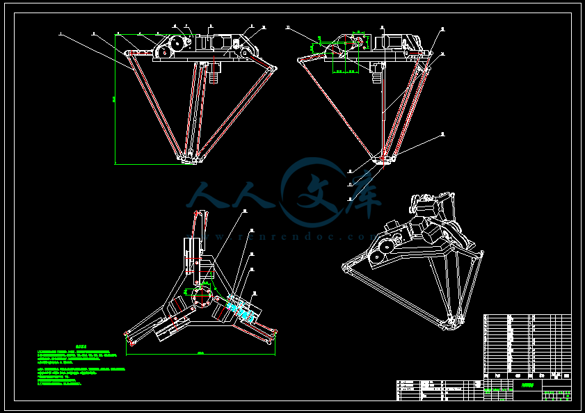
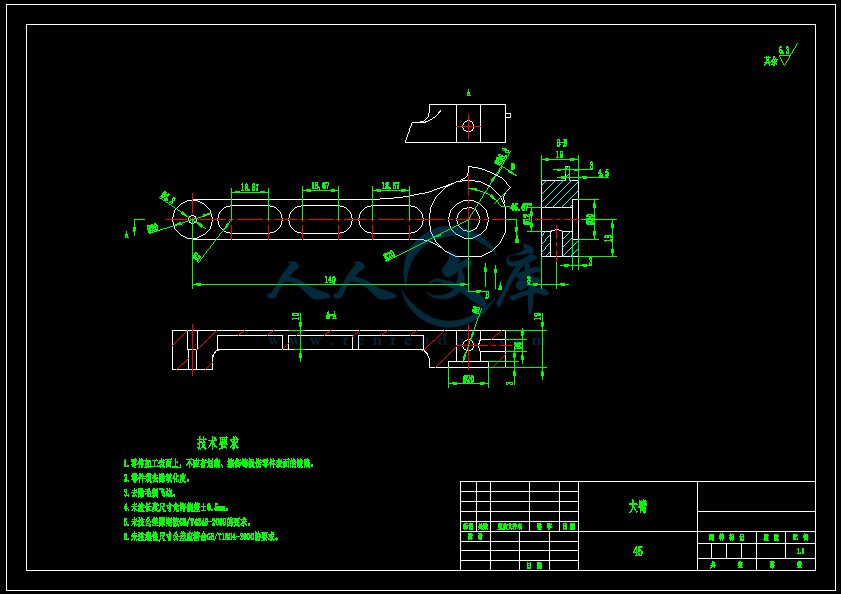
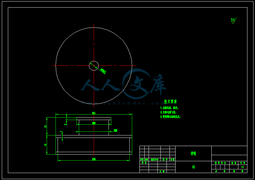
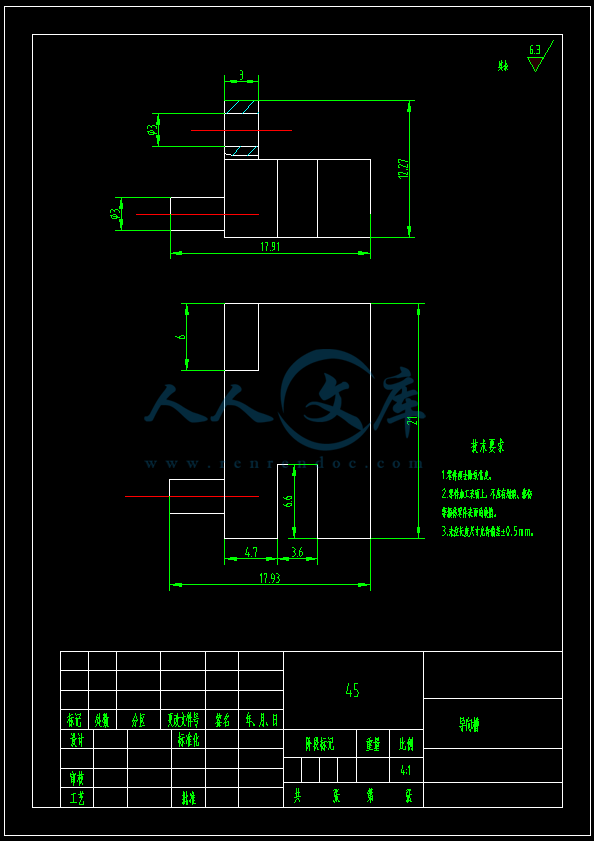
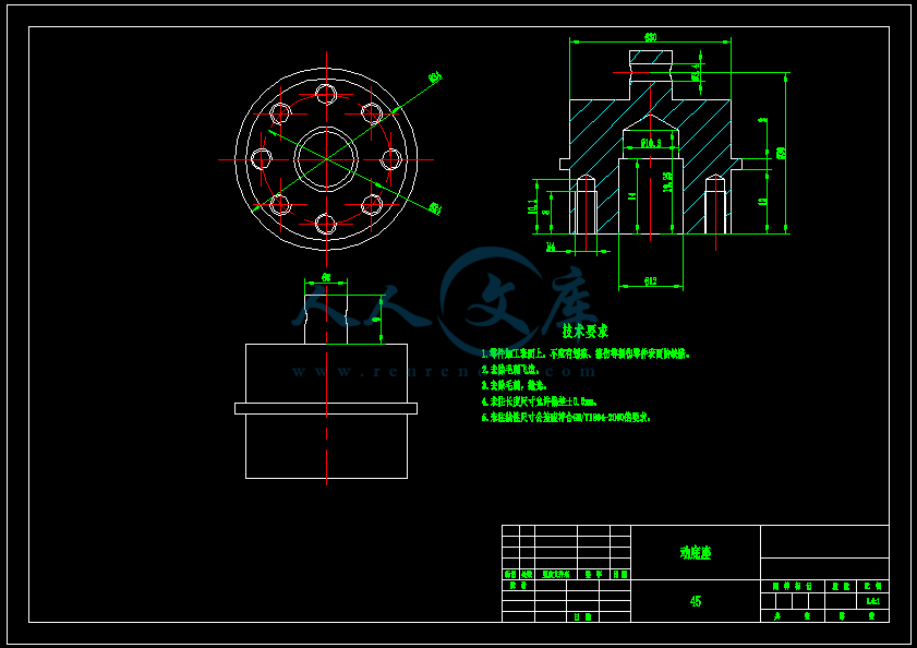
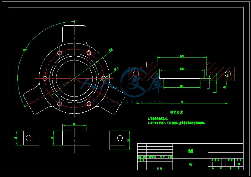
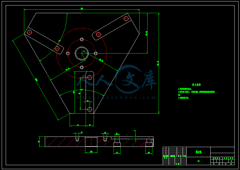
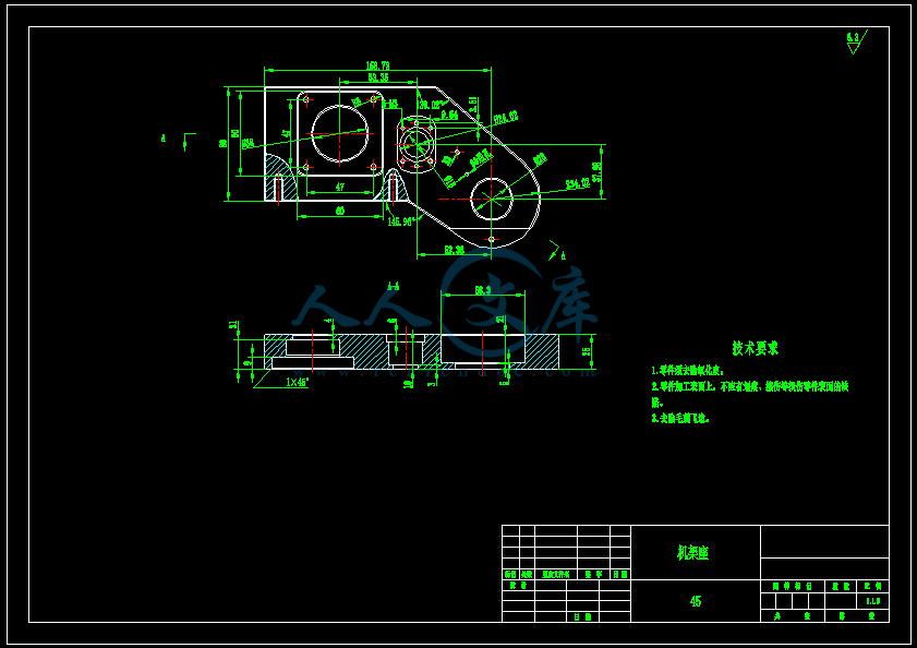
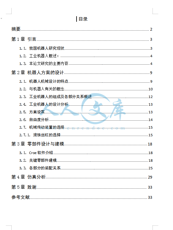
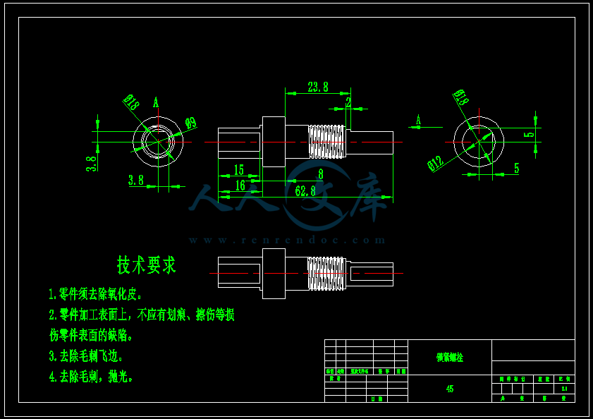
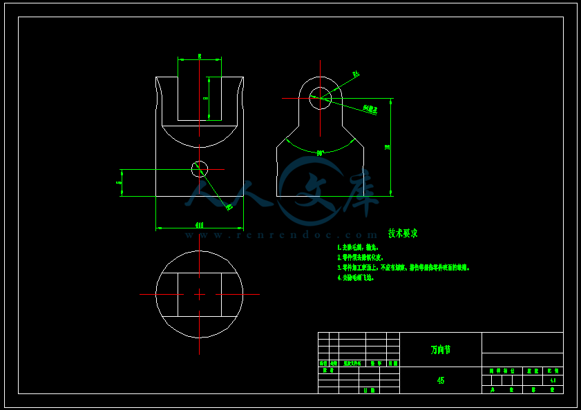
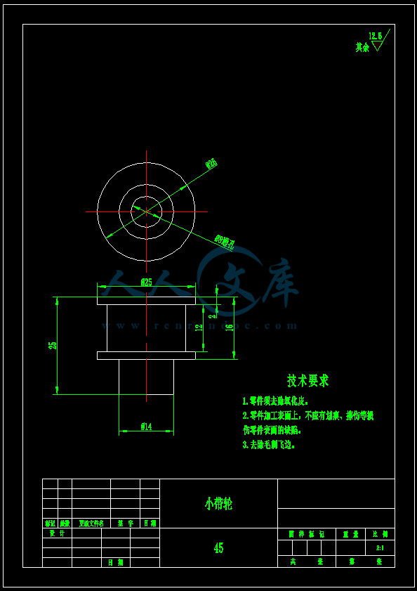
【温馨提示】压缩包内含CAD图有下方大图片预览,下拉即可直观呈现眼前查看、尽收眼底纵观。打包内容里dwg后缀的文件为CAD图,可编辑,无水印,高清图,压缩包内文档可直接点开预览,需要原稿请自助充值下载,所见才能所得,请见压缩包内的文件及下方预览,请细心查看有疑问可以咨询QQ:11970985或197216396

- 内容简介:
-
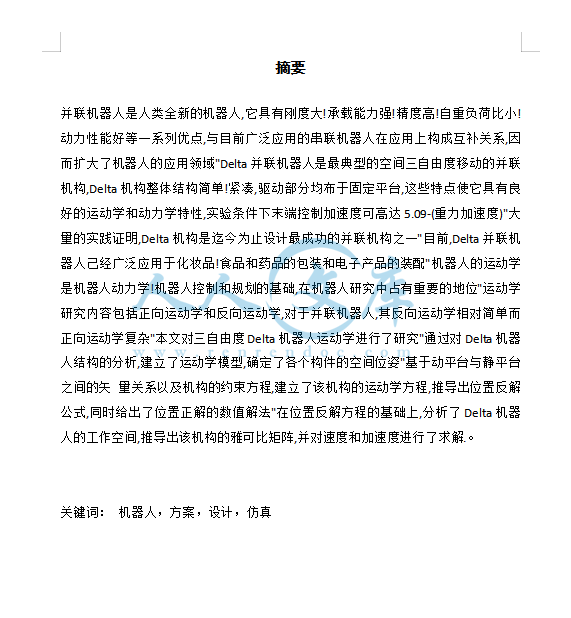
毕 业 设 计(论 文)外 文 参 考 资 料 及 译 文译文题目:由表面应力引起的纳米多孔金 悬臂梁的宏观弯曲学生姓名: 专业: 所在学院: 指导教师: 职称: Surface-Stress Induced MacroscopicBending of Nanoporous GoldCantileversDominik Kramer,*, Raghavan Nadar Viswanath, and Jo1rg Weissmu1ller,Institut fu r Nanotechnologie, Forschungszentrum Karlsruhe GmbH, 76021 Karlsruhe, Germany, and Fachrichtung Technische Physik, UniVersita t des Saarlandes, 66041 Saarbru cken, GermanyReceived January 13, 2004ABSTRACTNANOLETTERS2004 Vol. 4, No. 5793-796We report the preparation of composite foils consisting of two layers, one solid gold and one nanoporous gold. Tip displacements of several millimeters are observed when the foils are immersed in aqueous electrolytes and the electrochemical potential varied. This suggests that nanoporous metals could be used as the active component in actors, and it demonstrates for the first time that changes in the surface stress f of the metal-electrolyte interface can induce a macroscopic strain, orders of magnitude larger than the amplitudes which are reached in conventional cantilever bending experiments used to measure f.Changes of the shape of liquid mercury electrodes in response to changes of the electrical potential have been observed as early as the 19th century. In 1872, Gabriel Lippmann invented his capillary electrometer in which small voltage differences can be measured by observation of the displacement of a mercury meniscus. The Lippmann equation relates the surface tension of a liquid electrode to the electrode potential, and it isalso a good approximation for solids.1 However, the surface stress f of a solid is not even approximately equal to its surface tension , and it exhibits a different (generally, stronger)2dependence on the potential.1 Furthermore, due to the stiffness of solids, potential-dependent changes in the position or shape of solid surfaces are much smaller than those of liquidelectrodes. Highly sensitive extensometers3 were used to monitor the strain, and in the past decade, surface stress changes have been measured using atomic force microscope type techniques: thin metal films on the cantilevers are used as electrodes, and techniques as, for instance, laser beam deflection allow the tip displacement (in the lower nanometer range, e.g., in ref 4) induced by changes in the surface stress tobe measured.5-10 Because the surface stress in solids could hitherto only be detected in a laboratory environment using sophisticated equipment, it might be considered as an “exotic” phenomenon of little practical relevance. Even in thin film growth, where the* Corresponding author. E-mail: Dominik.Kramerint.fzk.de. Ad-dress: Dr. Dominik Kramer, Forschungszentrum Karlsruhe GmbH, Institut fu r Nanotechnologie, PO Box 3640, D-76021 Karlsruhe, Germany, Tel. +49-(0)7247 82 6379, Fax +49-(0)7247 82 6369. Forschungszentrum Karlsruhe. Universitat des Saarlandes.10.1021/nl049927d CCC: $27.50 2004 American Chemical Societyinterface-induced stress maybe large,its importanceremains the subject to current research.11More recently, surface stress induced length changes of 1.5 m have been observed in nanoporous mm-sized platinum cubes, an indication that the capillary effects can be enhancedby increasing the surface-to-volume ratio ,12 which takes on exceptionally large values in porous nano-structures. Since the pressure in the bulk required to balance the surface stress scales with independent of the geometry of themicrostructure,13 large volume changes and a considerable mechanical work density result from changes in the surface stress of the nanoporous metal.12 Therefore, it has been suggested that such materials may be attractive for use as actuators.14 However, integration of the porous metal into a device requires that it can be precisely and reproducibly shaped, and that it can be bonded to the parts of the device that transmit displacement and load. It has not been demonstrated so far how this can be achieved using nano-powder compacts; furthermore, while powder compacts support a considerable hydrostatic pressure, their resistance to shear stress may be poor. Here, we show that nanoporous metals prepared by dealloying a bulk solid solution exhibit similarly large strain amplitudes as nanopowder compacts, and that the porous material can be joined to solid metal foils to form a composite cantilever beam actuator. The charge-induced expansion or contraction of the porous metal gives rise to a biaxial stress component that results in a large bending of the foil. In this way, the effect of the interface-induced stress is amplified so that the deflection becomes visible to the naked eye: the tip moves by 3 mm, an increasePublished on Web 03/31/2004Figure 1. Scanning electron micrograph of the nanoporous gold structure obtained by etching silver-gold alloy in perchloric acid.by the factor 106 compared to previous cantilever bending experiments using a planar surface. This demonstrates that changes in the surface stress of nanoporous metals can be exploited to do work in cantilever bending, analogously towhat was recently reported for carbon nanotubes,15 vanadium oxide nanofibers,16 and conducting polymers.17Dealloying, the selective dissolution of the less noble component from a solid solution, is well-known to result innanoporous structures.18 Dealloying is attractive as a tech-nique for preparing nanoporous solids since it can be applied irrespective of the shape of the active part of a device - including, conceivably, lithographically shaped miniaturizedcomponents. Our samples were obtained by the dealloyingof Ag75Au25 master alloy sheets (see Methods). Figure 1 shows a scanning electron microscopy image of the nano-porous gold microstructure. The ligament size is ca. 20 nm.Cuboids of porous gold of dimension 1.21.2 1 mm3 were investigated in a commercial dilatometer equipped with an in-situ electrochemical cell. Figure 2A is the cyclic voltammogram (current vs potential curve) of a nanoporous gold sample immersed in 50 mM sulfuric acid, recorded in-situ in the dilatometer cell. The potential limits are given by the onset of hydrogen evolution (ca. -0.25 V) and gold oxidation (above 1 V). The voltammogram in Figure 2A is typical of a polycrystalline gold surface: The current is almost constant over the entire potential range, indicating a continuous capacitive double-layer charging anddischarging, in agreement with the known tendency of SO4-anions to interact only weakly with Au.19Figure 2B shows the change L in sample length versus the time as the potential is cycled between -0.26 and +1.05 V in 50 mM H2SO4. The length changes periodically and reversibly with the potential, with a small irreversible shrinking superimposed to that. When the reversible part of L is plotted versus the potential (Figure 2C), it is apparent that the length of the sample can be changed reproducibly by controlling the potential, with a small hysteresis of 0.1 V (or 0.02 m). The charge was obtained by integration of the current of Figure 2A and by setting the potential of zero charge (pzc) to 0.25 V compare ref 20. The graph of strain versus charge (Figure 2E) is highly reversible and linear bothFigure 2. In-situ dilatometry using 15 succesive cycles of the potential of a cuboid nanoporous gold sample in 50 mM sulfuric acid. (A)Cyclic voltammogram (current I versus the electrochemical potential E). (B) Length change L versus time t during the 15 cycles of (A).(C) Reversible part of L versus E, obtained by subtraction of an constant arbitrary value for each cycle. (D) Total charge Q versus E.(E) L/L0 versus Q. (A) and (C)-(E) display results of all 15 cycles superimposed.794Nano Lett., Vol. 4, No. 5, 2004in the negatively and positively charged regimes; it exhibits a change in slope near the pzc. A similar linear correlation has been observed for a Au(111) surface by STM,21,22 but the break near the pzc of Figure 2E was not resolved there.It is a matter of debate in how far the potential dependence of the surface stress reflects the details of the bonding of adsorbates to the surface (see ref 10 and references therein). We have carried out experiments using perchloric acid as the electrolyte, and found the results to be in qualitative agreement with Figure 2 (see Supporting Information). Sincethe ClO4- ion adsorbs even more weakly than SO4-, this finding is compatible with the notion that the potential-induced strain does not intrinsically require the formation of the chemical bonds involved in specific adsorption; this would imply that the change in surface stress reflects the modifiedbonding in the space-charge layer within the metal surface.2,12 Two further observations in support of this notion are: (i) whereas we find Au to contract at negative potential, carbon nanotubes show the opposite effect, expansion upon negativecharging,15 which indicates that the change in surface stress is strongly related to the nature of the bonding in the solid; and (ii) in-situ X-ray adsorption near edge spectroscopy (XANES) data show a significant change in d-band occupancy in Pt nanoparticles as the Pt-electrolyte interface is charged, confirming that the superficial electronic structure of the solidcan be changed.23 If the change in surface stress and the surface-induced strain in our samples are indeed a consequence of the modified bonding in the metal, then theresults provide support for a more general concept:24 by controlling the net charge in space-charge layers at metal surfaces, one can modify the electronic density of states and, thereby, the local properties of the matter at the surface. In nanomaterials, which have a large surface-to-volume ratio, this will result in changes of the overall properties, opening a way for tuning all those materials properties that depend on the density of states.The action of the surface stress can be amplified by use of bilayer foils. Each of the foils consists of a layer of porous Au bonded to a layer of solid Au, see the cross-sections in Figure 3A. When the foil is immersed in an electrolyte, and its potential varied, then the porous layer will tend to expand or contract, whereas the solid layer will tend to maintain its dimensions. This will result in shear stress at the interface between the two layers, and in a bending of the foil, quite analogous to the effect of the differential thermal expansion used in bimetal thermometers. A similar arrangement has alsobeen used to produce carbon nanotube actuators.15To make the bilayer foils, a 2 mm thick sheet of silver-gold alloy was cold-welded to a 0.5 mm thick sheet of pure gold by rolling. After reducing the thickness of the stack to 30 m by further rolling, the resulting foil was annealed for stress relief and strips 35-40 mm long and 2 mm wide cut from it. Dealloying resulted in a composite foil consisting of a 6 m thick layer of solid Au covered with 24 m of porous Au. Twofoils were immersed in 1 M HClO4 and wired as the working and the counter electrodes, respectively. Figures 3A and 3B show a schematic drawing and a photograph of the experimental setup. Both foils undergo aNano Lett., Vol. 4, No. 5, 2004Figure 3. Illustration of the operation of the composite foils. (A) schematic cross-section through an electrochemical cell comprising two identical foils that serve (interchangeably) as working electrode and counter electrode. (B-D) photographs of an electrochemical cell with two bimetallic stripes (nanoporous gold on gold), similar to the schematic in (A). The electrolyte is 1 M perchloric acid. The lower scale of the ruler is calibrated in mm. (C, D) Two enlarged views of the cell in (B), showing the tip of one of the foils with two different voltages applied between the two foils, +1 V (C) and -1 V (D). It is seen, that when the voltage is inversed, the tip moves by ca. 3 mm. The arrows serve as reference markers, emphasizing the tip displacement.reversible bending as the voltage is changed. Figures 3C,D show enlarged views of the tip of one of the foils before and after inverting the applied voltage. When the potential difference between the electrodes is switched from -1 V to +1 V, the tip moves by as much as 3 mm. Thus, compared to cantilever bending experiments using planar surfaces, the displacement resulting from surface stress changes has increased from few nanometers to the millimeter regime,that is, by about a factor of 106. A video clip showing the actuator operation is displayed as Supporting Information. For the first time, the effects potential-induced changes of the interface stress, which had previously required sophisticated experimental equipment, have become visible to the naked eye.For actuator applications, the response time is important. Figure 4A shows the time-dependent L during a series of795Figure 4. (A) Length change L of the sample in 50 mM sulfuric acid versus time, measured in the dilatometer during a series of potential jumps from -0.2 to 1 V and back (dashed line: potential).(B) Frequency dependence of the amplitude during potential jumps (rectangular wave) in sulfuric acid. Large squares: Amplitude of the charge curve. Small circles: Amplitude of the length change as measured in the dilatometer. The dilatometersmaximum sampling rate of 10 s-1 limits the experimental strain amplitude at high frequency.potential jumps from -0.2 V to 1 V and back. The half-times of the jumps in current and strain are 220 and 270 ms.Because of the limited sampling rate (10 s-1) of the dilatometer, the time constant obtained from the charging curves is considered more accurate. The strain amplitude at a frequency of 0.3 Hz is almost identical to that during slower switching (Figure 4B), which is consistent with the response time given above. The bilayer foils react similarly fast, despite the drag of the electrolyte. The intrinsic time scale is given by the time constant of the charging current, which was determined as 25 ms, considerably faster than in the thicker dilatometer samples. This agrees qualitatively with the expectation that the drift of ions into the pores will be accelerated as the path is shortened.The large mechanical response induced by changes in the surface stress predestines porous gold as an active component in sensors, especially if its surface is modified by adsorption, e.g., of molecules functionalized by thiol groups. These can be chosen to react selectively with specific molecules, for instance, antibodies; the reaction changes the surface stress, e.g., by steric repulsion of the product, and sensors detectingthese changes have been proposed and tested.8,25-27 Their sensitivity may be significantly enhanced by using nano-porous layers instead of planar surfaces.In addition to its performance as a simple actor producing reversible strain controlled by an applied voltage, the deviceshown in Figure 3 can also be regarded as a primitive voltmeter. If the tip displacement was observed with an optical microscope as in Lippmanns device, it would be suited to measure small voltage differences. Thus, Lipp-manns 19th century voltmeter based on changes of the surface tension of liquid mercury interface has found a modern equivalent based on changes in the surface stress of a solid metal.Acknowledgment. Stimulating discussions with H. Gle-iter and support by DFG (Center for Functional Nanostruc-tures) are gratefully acknowledged.Supporting Information Available: Experimental de-tails, two additional Figures (S1, S2), and a video showing the movement of the bilayer foils. This material is available free of charge via the Internet at .References(1) Lipkowski, J.; Schmickler, W.; Kolb, D. M.; Parsons, R. J. Elec-troanal. Chem. 1998, 452, 193-197.(2) Schmickler, W.; Leiva, E. J. Electroanal. Chem. 1998, 453, 61-67.(3) Lin, K. F.; Beck, T. R. J. Electrochem. Soc. 1976, 123, 1145-1151.(4) Haiss, W.; Sass, J. K. J. Electronanl. Chem. 1995, 386, 267-270.(5) Ibach, H. Surf. Sci. Rep. 1997, 29, 195-263. Ibach, H. Surf. Sci. Rep.1999, 35, 71-73.(6) Raiteri, R.; Butt, H.-J. J. Phys. Chem. 1995, 99, 15728-15732.(7) Miyatani, T.; Fujihira, M. J. Appl. Phys. 1997, 81, 7099-7115.(8) Ibach, H.; Bach, C. E.; Giesen, M.; Grossmann, A. Surf. Sci. 1997, 375, 107-119.(9) Raiteri, R.; Butt, H.-J.; Grattarola, M. Electrochim. Acta 2000, 46, 157-163.(10) Friesen, C.; Dimitrov, N.; Cammarata, R. C.; Sieradzki, K.Langmuir 2001, 17, 807-815.(11) Cammarata, R. C.; Trimble, T. M.; Srolovitz, D. J. J. Mater. Res. 2000, 15, 2468-2474.(12) Weissmu ller, J.; Viswanath, R. N.; Kramer, D.; Zimmer, P.; Wu rschum, R.; Gleiter, H. Science 2003, 300, 312-315.(13) Weissmu ller, J.; Cahn, J. W. Acta Mater. 1997, 45, 1899-1906.(14) Baughman, R. H. Science 2003, 300, 268-269.(15) Baughman, R. H.; Cui, C.; Zakhidov, A. A.; Iqbal, Z.; Barisci, J. N.; Spinks, G. M.; Wallace, G. G.; Mazzoldi, A.; De Rossi, D.; Rinzler, A. G.; Jaschinski, O.; Roth, S.; Kertesz, M. Science 1999, 284, 1340-1344.(16) Gu, G.; Schmid, M.; Chiu, P.-W.; Minett, A.; Fraysse, J.; Kim, G.-T.; Roth, S.; Kozlov, M.; Mun oz, E.; Baughman, R. H. Nature Mater. 2003, 2, 316-319.(17) Baughman, R. H. Synth. Met. 1996, 78, 339-353.(18) Erlebacher, J.; Aziz, M. J.; Karma, A.; Dimitrov, N.; Sieradzki, K.Nature 2001, 410, 450-453.(19) Kolb, D. M. Prog. Surf. Sci. 1996, 51, 109-173.(20) Kramer, D., Thesis, University of Ulm, Germany, 2000.(21) Haiss, W.; Nichols, R. J.; Sass, J. K.; Charle, K. P J. Electroanal. Chem. 1998, 452, 199-202.(22) Nichols, R. J.; Nouar, T.; Lucas, C. A.; Haiss, W.; Hofer, W. A.Surf. Sci. 2002, 513, 263-271.(23) Mukerjee, S.; Srinivasan, S.; Soriaga, M. P.; McBreen, J. J. Electrochem. Soc. 1995, 142, 1409-1422.(24) Gleiter, H.; Weissmu ller, J.; Wollersheim, O.; Wu rschum, R.Acta Mater. 2001, 49, 737-745.(25) Berger, R.; Delamarche, E.; Lang, H. P.; Gerber, Ch.; Gimzewski, J. K.; Meyer, E.; Gu ntherodt, H.-J. Science 1997, 276, 2021-2024.(26) Chen, G. Y.; Thundat, T.; Wachter, E. A.; Warmack, R. J. J. Appl. Phys. 1995, 77, 3618-3622.(27) Fritz, J.; Baller, M. K.; Lang, H. P.; Strunz, T.; Meyer, E.; Gu ntherodt, H.-J.; Delamarche, E.; Gerber, Ch.; Gimzewski, J. K. Langmuir 2000, 16, 9694-9696.NL049927D796Nano Lett., Vol. 4, No. 5, 2004本文研究了一种双层复合材料箔的制备,其中一层为固体金,另一层为纳米多孔金。当箔浸入电解质水溶液中,并改变溶液的电化学势,可以观察到数毫米大小的端部位移。这一现象表明纳米多孔金属可以作为作动器中的应激组件,还首次揭露了金属-电解液界面上表面应力f的改变将引起宏观应变,该应变的大小比用于测量表面应力f的传统悬臂梁弯曲实验中所能达到的振幅要高几个数量级。早在19世纪,人们就已观察到,在电势改变时液态汞电极将会产生形状改变。1872年,Gabriel Lippmann(加布里埃尔李普曼,外国人的名字不必翻译)发明了毛细静电计,可通过观察一个水银弯曲面的位移来测得微小的电压改变。李普曼方程建立了液态电极的表面张力和电极电势的相关关系,而且对固体电极也可以获得令人满意的近似结果1。然而,固体的表面应力f并不近似等于其表面张力,并表现出对电势的不同依赖性1(一般而言依赖性更强)2。进一步讲,由于固体具有一定的刚度,其表面依赖于电势的位置和形状改变远小于液体电极。高敏延展计3用于监测应变,在过去的十年间,利用原子力显微镜技术已可测量表面应力的改变:将薄金属片置于悬臂梁上作为电极,然后采取激光束偏转分析技术,就可以得到由表面应力改变引起的悬臂梁末端位移(可达到纳米级,如参4)5-10。然而由于目前仅能在实验室环境内依托精密仪器检测到固体的表面应力,所以这一发现还只被视作一种缺少实用价值的“独特”现象。即使在界面导致应力较大的薄膜生长方面,其重要性也有待进一步研究11。最近,在具有毫米量级尺寸的纳米多孔铂立方体上观测到了由于表面应力引起的长度变化,达到1.5m。这说明提高表体比能够放大毛细管效应12,而多孔纳米结构的表体比非常大。由于块体材料中平衡表面应力所需的体积应力会随变化,而不依赖于微观结构的几何特性,所以纳米多孔金属的表面应力变化将引起可观的机械功密度及大的体积改变12。因此,这类金属被认为在作动器制造方面前景诱人14。然而,将多孔金属集成在设备上需要精确且可重复化的多空金属成型工艺,并且能与设备上传递位移和荷载的部分紧密联结。目前为止,使用纳米粉末一体化压实技术还不能达到这些要求,因为虽然一体化纳米粉末抗压能力优良,但其抗剪能力很差。本文中展示了利用固熔块体脱合金法制备的纳米多孔金属不仅具有与一体化纳米粉末压实相近的大应变幅值,并可与固体金属箔有效粘结,制造出一种复合悬臂梁作动器。通电后,多孔金属发生延展或收缩,产生双轴平面应力分量,从而引起箔的大幅度弯曲。这样一来,界面导致应力所产生的效应被放大至肉眼可见的挠度,梁末端移动了3mm,比之前使用光滑平面的悬臂梁弯曲实验提高了106倍。这说明纳米多孔金属中表面应力的变化可被用于悬臂梁弯曲实验,类似于最近报导的碳纳米管15,钒氧化物纳米纤维16和导电高分子17。众所周知,将固溶物中占比较小的组分通过脱合金法选择性溶解,能够获得纳米多孔结构18。脱合金法作为一种制备纳米多孔固体的技术,其优点在于应用时不受设备应激部件形状的限制(包括刻蚀技术成型的微型组件)。本文所使用的试样是通过对Ag75Au25母合金片进行脱合金腐蚀制备的(详见“方法”一章)。图1为纳米多孔金微观结构的扫描电子显微镜照片,系带尺寸约为20nm。使用配备有原位电化学电池的商业膨胀计,对
- 温馨提示:
1: 本站所有资源如无特殊说明,都需要本地电脑安装OFFICE2007和PDF阅读器。图纸软件为CAD,CAXA,PROE,UG,SolidWorks等.压缩文件请下载最新的WinRAR软件解压。
2: 本站的文档不包含任何第三方提供的附件图纸等,如果需要附件,请联系上传者。文件的所有权益归上传用户所有。
3.本站RAR压缩包中若带图纸,网页内容里面会有图纸预览,若没有图纸预览就没有图纸。
4. 未经权益所有人同意不得将文件中的内容挪作商业或盈利用途。
5. 人人文库网仅提供信息存储空间,仅对用户上传内容的表现方式做保护处理,对用户上传分享的文档内容本身不做任何修改或编辑,并不能对任何下载内容负责。
6. 下载文件中如有侵权或不适当内容,请与我们联系,我们立即纠正。
7. 本站不保证下载资源的准确性、安全性和完整性, 同时也不承担用户因使用这些下载资源对自己和他人造成任何形式的伤害或损失。

人人文库网所有资源均是用户自行上传分享,仅供网友学习交流,未经上传用户书面授权,请勿作他用。
 川公网安备: 51019002004831号