摆线齿轮泵外转子加工工艺及主要工装设计
49页 14000字数+说明书+任务书+开题报告+工艺卡片+5张CAD图纸【详情如下】
任务书.doc
工艺卡片14张.dwg
拉刀设计.dwg
摆线齿轮泵外转子加工工艺及主要工装设计开题报告.doc
摆线齿轮泵外转子加工工艺及主要工装设计说明书.doc
毕业实习总结.doc
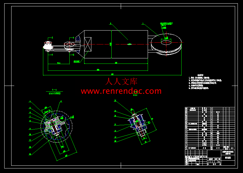
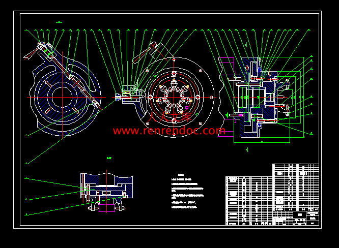
磨削装置装配图磨胎.dwg
磨头装配图.dwg
零件图.dwg
摘 要
本文就摆线的基本概念作了介绍,并阐述摆线齿轮泵中,外转子的加工工艺过程、工装设备以及成形拉刀的设计计算。摆线齿轮泵中以内转子为主动轮,外转子为从动轮,在设计中要求外转子精度高,同时考虑到经济成本,在设计加工工艺时,尽量采用既高精度又经济的方式。而且还介绍了在单件生产纲领下,进行摆线齿轮泵外转子曲面磨削的方法。确定了磨削参数及工艺装备。本加工方法具有传动链短,砂轮修磨简单,可稳定的保持加工精度。
关键词:摆线齿轮外转子;工艺;结构设计;工装设备;成形拉刀。
Abstract
This article introduced the basic concept of cycloid and cycloid gear pump described, the outer rotor of the machining process, tooling equipment and design calculation of forming broach. Within the rotor cycloidal gear pump for the driving wheel, outer rotor to the driven wheel, the rotor in the design requirements of high precision, taking into account economic costs, in the design process, try to use the high-precision and economical way. But also introduced the program in the single production under the cycloid gear pump outer rotor surface grinding method. Determine the parameters and processes of grinding equipment. This processing method has a short transmission chain, grinding wheel simple, steady and precision
Keywords: cycloidal gear outer rotor; process; structural design; tooling equipment; forming broach
目 录
摘 要I
第1章 绪论1
1.1 齿轮泵概述1
1.2 齿轮泵发展趋势1
1.3 外转子设计的基本要求3
第2章 外转子的加工工艺设计4
2.1 零件的分析4
2.1.1 零件的作用4
2.1.2 零件工艺分析4
2.2 工艺规程设计4
2.2.1 确定毛坯的制造形式4
2.2.2 基面的选择4
2.2.3 制定工艺路线5
2.2.4 机械加工余量,工序尺寸及毛坯尺寸确定7
第3章 夹具设计18
3.1 拉胎18
3.1.1 问题的提出18
3.1.2 定位基准的选择18
3.1.3 定位误差分析18
3.1.4 夹紧力18
3.1.5 胎具结构18
3.2 磨胎18
3.2.1 问题的提出18
3.2.2 定位基准的选择18
3.2.3 夹具结构19
3.3 磨头21
3.4 打磨砂轮工具22
第4章 内曲面成形拉刀设计23
4.1 粗拉刀设计23
4.1.1 切削部设计23
4.1.2 校准部设计28
4.1.3 其它部分及拉刀总长度29
4.1.4 拉刀强度计算及拉削力的校验32
4.2 精拉刀设计33
4.2.1 参数选择33
4.2.2 校核最大拉削力36
4.2.3 拉刀强度校验36
4.2.4 拉刀总长度37
结束语39
致 谢40
参考文献41
CONTENTS
AbstractII
Chapter One Introduction1
1.1 Gear Pump Overview1
1.2 Development Trend of gear pump1
1.3 The basic requirements of external rotor design3
Chapter Two External rotor design process4
2.1 Parts of the analysis4
2.1.1 Parts of the role4
2.1.2 Parts Process Analysis4
2.2 Process planning4
2.2.1 Determine the form of blank manufacturing4
2.2.2 The choice of the base surface4
2.2.3 Development of process routes5
2.2.4 Machining allowance, process to determine the size and rough size7
Chapter Three Fixture Design18
3.1 Pull tire18
3.1.1 Proposed of the problems18
3.1.2 The choice of locating datum18
3.1.3 Orientation error18
3.1.4 Clamping force18
3.1.5 Mold structure18
3.2 Tire wear18
3.2.1 Proposed of the problems18
3.2.2 The choice of locating datum18
3.2.3 Fixture Structure19
3.3 Grinding head21
3.4 Tool grinding wheel22
Chapter Four Broach the surface forming the design23
4.1 Rough broach design23
4.1.1 Department of Design Cutting23
4.1.2 Department of Design Calibration28
4.1.3 Other parts and the total length of broach29
4.1.4 Broach broaching force strength calculation and validation32
4.2 Essence broach design33
4.2.1 Parameter selection33
4.2.2 Checking the maximum broaching force Fmax 36
4.2.3 Broach strength check36
4.2.4 The total length of broach 37
Conclusion39
Thanks for40
References41


 川公网安备: 51019002004831号