相关资料.doc

4S店汽车维修专用升降机设计【机+液】【5张图纸】【优秀】

收藏

压缩包内文档预览:
预览图 预览图 预览图 预览图 预览图 预览图 预览图 预览图 预览图 预览图 预览图 预览图 预览图 预览图 预览图 预览图 预览图 预览图
编号:271799    类型:共享资源    大小:997.65KB    格式:RAR    上传时间:2014-04-08 上传人:上*** IP属地:江苏
48
积分
关 键 词:
4S店汽车 维修 专用 升降机 设计 图纸 优秀 优良
资源描述:

4S店汽车维修专用升降机设计

47页 21000字数+说明书+5张CAD图纸

4S店汽车维修专用升降机设计说明书.doc

底座-2.dwg

整机图-2.dwg

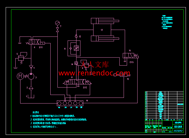
液压系统图-2.dwg

液压缸装配图.dwg

相关资料.doc

计划周记进度检查表-5.xls

论文封面.doc

零件图-2.dwg


摘  要

   当前在汽车维修中所使用的液压同步升降平台在汽车的维修方面发挥着重要的作用,通过对同步升降平台的各种液压阀、液压缸、液压泵站的创新改进,使得液压同步升降平台拥有运行平稳、噪声低、响应速度快、同步精度高等优点,对于在我国汽车的维修与保养中起着不可替代的作用,应用前景广泛。

   4S店汽车维修专用升降机是双铰接剪叉式升降机,它是在原由的剪叉式升降机的基础上,运用现在的灵活性、安全性、经济性等指标;结构以能够满足灵活性要求较高的汽车维修需要为前提而设计的。

   通过对双铰接剪叉式升降机机构位置参数和动力参数的分析,结合具体实例,对机构中两种液压缸布置方式分析比较,并根据要求对液压传动系统各部分进行设计计算最终确定液压执行元件-液压缸,通过对叉杆的各项受力分析确定台板与叉杆的载荷要求,最终完成剪叉式液压升降机的设计要求。


关键字:升降台;剪叉式;结构设计;液压


目 录

摘  要I

AbstractII

目 录III

第一章  绪    论1

1.1 升降机的发展简史1

1.2 汽车升降机的设计特点2

1.3 汽车升降机的安全保证措施2

1.3.1 设计制造方面的安全保证措施3

1.3.2 使用维护方面的安全保证措施3

第二章 剪叉式升降台的应用及其受力分析的讨论5

2.1 剪叉式升降平台的三种结构形式5

2.2 双铰接剪叉式升降平台机构的位置参数计算6

2.3 双铰接剪叉式升降平台机构的动力参数计算8

2.4 剪叉式升降平台机构设计时应注意的问题9

2.5 针对性比较小实例:9

2.6双铰接剪叉式升降平台机构中两种液压缸布置方式的分析比较11

2.6.1问题的提出:11

2.6.2两种布置方式的分析和比较:12

2.6.3实例计算14

第三章 液压传动系统的设计计算17

3.1明确设计要求 制定基本方案:17

3.2制定液压系统的基本方案17

3.2.1确定液压执行元件的形式17

3.2.2 确定液压缸的类型18

3.2.3 确定液压缸的安装方式18

3.2.4 缸盖联接的类型19

3.2.5拟订液压执行元件运动控制回路19

3.2.6液压源系统19

3.3确定液压系统的主要参数19

3.3.1载荷的组成与计算:19

3.3.2初选系统压力22

3.3.3计算液压缸的主要结构尺寸22

3.3.4确定液压泵的参数25

3.3.5管道尺寸的确定26

3.3.6油箱容量的确定27

3.4  液压缸主要零件结构、材料及技术要求27

3.4.1缸体27

3.4.2 活塞28

3.4.3 活塞杆29

3.4.4活塞杆的导向、密封和防尘29

3.4.5液压缸的排气装置30

3.4.6 液压缸安装联接部分的型式及尺寸30

3.4.7 绘制液压系统原理图31

第四章 台板与叉杆的设计计算34

4.1确定叉杆的结构材料及尺寸34

4.2横轴的选取37

第五章 总结39

参考文献41

   (3)丝绳的选择。为了减少滑轮直径从而缩小寄生机立柱的断面尺寸,应该选用高柔度的钢丝绳。钢丝绳应有较高的安全系数,一般应达8。为此,应增加钢丝绳钢丝的数目。如英国某公司3t系列的升降机所采用的钢丝绳的直径为9mm,两根并列,每根37股,每股6根钢丝。滑轮通常用钢材制成,而该公司采用玻璃纤维与尼龙混合制成(50%的玻璃纤维、50%的尼龙)。这样,不仅价格便宜,还能减轻钢丝绳的磨损,延长其使用寿命。

1.3 汽车升降机的安全保证措施

    今天全世界都对在危险作业环境下工作的人们的安全寄予极大的关注。汽车升降机具有潜在的危险,因为人们要在其下面工作;当其升降时如不小心,也会碰伤手足。近年来不少国家还制定了专门性法规,以防止或至少使安全事故的可能性降低到最低限度。

   汽车升降机的安全保证措施主要从两方面着手:一方面从设计制造方面采取措施,好提高汽车升降机的安全技术特性;另一方面则应在使用维修过程中遵循严格的操作规程,保证汽车升降机能在良好的技术状态下正确地运行。现分别说明与后。

  1.3.1 设计制造方面的安全保证措施

   当今世界上的许多先进技术,如自动控制\光电开关等,已广泛应用到各种安全装置的设计领域,因而在设计制造升降机时,应结合产品的特点,积极采用先进可靠实用的现代安全技术。以下仅列举多数升降机普遍采用的安全措施。

   (1)升降机应能经受超负荷试验(包括举升和支撑),一般应为最大举升能力的125%此时升降机的构件不得有任何永久性的变形和损坏。

   (2)所有的操作控制机构均采用“双重保险”,以防误操作,即升降机运行前必需操作两个控制机构(或按钮开关)后才能驱动。

   (3)所有的控制电路均采用失效保护,即任何单个元件失效,也不会使升降机坠或上升所造成非常危险的局面。

   (4)所有的升降机器件均应有第二支撑系统。原有的提升系统失效时,它能自动进行有效的支撑。

   (5)所有的柔性提升手段,如钢丝绳,链条等,均应有足够的安全系数,并在制造厂设置的保护罩内传动。

   (6)所有的运动零件均应有防护装置,以免撞击操作人员的任何部位,特别是手,足,衣服等。

   (7)所有升降机的设计均应把举升重物滑移的可能性降低到最低限度。


  1.3.2 使用维护方面的安全保证措施

   使用维护方面的安全保证措施涉及的范围很广,包括升降机有使用前的准备工作,举升汽车时应该注意的事项,承载时的稳定性,降下汽车时的注意事项,日常和定期维修检查工作等。虽然汽车升降机已有70年的历史,其设计原理并无多大改变;但如果忽视安全要求,超载使用,疏忽大意,仍然会造成严重事故,甚至发生人身伤亡。因此安全问题一定要引起使用单位和操作人员的高度重视。首先,应选购那些安全性能良好的汽车升降机,另外,还应认真学习和理解说明书中的各项安全注意事项并认真贯切执行。这里仅就使用维护升降机时普遍应当注意的事项说明于后。

   (1)使用中的升降机每天都应进行检查。发现有效故障或零部件损坏时,不得再使用。维修时应采用该升降机的制造厂所提供的配件,不得随意代替或自制。

   (2)升降机不得超载使用。每台升降机的额定载荷均注明在设备的铭牌上。特别要注意防止偏载,即整机虽未超载而某一举升臂确已超过允许的额定载荷。故欲举升那些前后轴载荷严重分配不均的汽车时应特别注意,能满足要求的才能装载使用。

   (3)安置汽车和使用升降机均应由经过培训并经考核合格的人员操作。

   (4)举升汽车时,车内不得有人。升降机升降和使用时,顾客和无关人员应远离升降机。

   (5)升降机区域内不得有任何障碍物,如油脂、废物、瓦砾等。

   (6)当汽车驶上升降机前,应清除通道,不得驶过或撞击举升臂,连接器,车轴支撑器等,以防损坏升降机或汽车。

   (7)在升降机上承载汽车时应仔细操作。将升降机的支撑器安置到汽车制造厂推荐的升降机逞力接触点。只有当支撑器与汽车上的承力点接触严密后才能将升降机升起;对其接触的严密性进行认真检查后,才能将汽车举升到需要的工作高度。

   (8)要注意某些汽车上的零部件由于移动或安装位置的不同会引起重心的急剧变化,从而导致举升汽车时的不稳定。

   (9)升降机降下前,应将汽车下面的工具箱,台架及其它设备全部移开。要降下升降机前,还必须松开锁紧装置。

   注意:如欲在汽车下面进行维修作业时,应将升降机提升到足够的高度,以便锁紧装置啮合。


内容简介:
编号无锡太湖学院毕业设计(论文)相关资料题目: 4S店汽车维修专用升降机设计 信机 系 机械工程及自动化专业学 号: 0923092学生姓名: 武文琦 指导教师: 范圣耀 (职称:副教授 ) (职称: )2013年5月20日目 录一、毕业设计(论文)开题报告二、毕业设计(论文)外文资料翻译及原文三、学生“毕业论文(论文)计划、进度、检查及落实表”四、实习鉴定表无锡太湖学院毕业设计(论文)开题报告题目: 4S店汽车维修专用升降机设计 信机 系 机械工程及自动化 专业学 号: 0923092 学生姓名: 武文琦 指导教师: 范圣耀 (职称:副教授 ) (职称: )2012年11月25日 课题来源经老师的介绍在工厂实习,经过几个月的亲身实践,我对汽车维修专用升降机有了一个系统的了解,因此选择了自己熟悉的产作为毕业论文的课题。科学依据(包括课题的科学意义;国内外研究概况、水平和发展趋势;应用前景等)(1)课题科学意义随着汽车使用量的迅速增加,社会对汽车维修工具和设备的工作效率也越来越高。由此原因,设计一种维修设备,它可根据汽车维修部位的不同而随时调整汽车的位置,方便维修,减轻维修人员的劳动负荷从而提高工作效率,就成为必然需要。具有结构紧凑,占地面积小,安装和拆卸操作方便,故障率低,常见故障易处理,维护方便等优点的汽车升降机,就可以满足汽车维修对提高工作效率的要求。本次毕业设计的题目来源于生产第一线,所设计的产品具有实用价值,已经有成熟产品生产。我们可以参考现有产品做出的改进设计,使产品机构更合理、更实用、更可靠。(2)汽车升降机的研究状况及其发展前景我国每年升降平台市场成交额高达500亿元左右,但其中却有100多亿元的市场被国外升降平台企业占领。要改变这种现状,提高升降平台质量是关键。升降平台在机械产品中占有相当大的比重。据国外工业发达国家统计,升降平台的产值是压缩机、风机和泵三者的总和,约占整个机械工业产值的5%。同时,作为重大技术装备的重要组成部分,尤其是在电力、石化、冶金、城市供排水系统中,升降平台更是起着关键作用,而且用量非常大。目前,我国升降平台企业约6000余家,其中年产值超过500万元的有900家。国内上市的升降平台公司3家,即中核科技、洪城股份、广东明珠。去年,中核科技主营业务收入2.35亿元,洪城股份主营业务收入1.46亿元,广东明珠主营业务收入1.5亿元。这些企业,无论是其规模,还是产品质量,目前都无法与国外同类企业抗衡。目前,国内外升降平台的发展趋势主要有以下五个方面:(1)升降平台的全球化趋势 (2)以跨国公司为主导,产业链细分的趋势 (3)以科技中心控制升降平台中心的新趋势 (4)升降平台的信息化、虚拟化趋势 (5)升降平台的绿色化趋势向环保化或绿色化方向发展研究内容 气液动剪叉式升降平台具有制造容易、价格低廉、坚实耐用、便于维修保养等特点。在民航、交通运输、冶金、汽车制造等行业逐渐得到广泛应用。通过对汽车专用升降平台的技术参数,结合具体实例,对机构中两种液压缸布置方式分析比较,并根据要求对液压传动系统个部分进行设计计算最终确定液压执行元件-液压缸,通过对叉杆的各项受力分析确定台板与叉杆的载荷要求,最终完成汽车专用升降平机的设计要求。拟采取的研究方法、技术路线、实验方案及可行性分析研究的内容(1)举升机台板降到下位时,与地面应尽可能在同一平面上。为此,在保证强度和刚度的前提下,应尽可能降低举升机台板和横梁的高度。在条件许可时,举升机台板(或横梁)应选择专用型钢或用钢板拆弯成形。(2)正确选择传动方式。采用机械传动(螺母、螺杆)或液压传动(油缸),均用电动机驱动。机械传动的成本较高,耗能较多,但安全性较好。(3)丝绳的选择。为了减少滑轮直径从而缩小寄生机立柱的断面尺寸,应该选用高柔度的钢丝绳。钢丝绳应有较高的安全系数,一般应达8。为此,应增加钢丝绳钢丝的数目。这样,不仅价格便宜,还能减轻钢丝绳的磨损,延长其使用寿命。研究计划及预期成果研究计划:2012年11月12日-2012年12月2日:按照任务书要求查阅论文相关参考资料,填写毕业设计开题报告书。2012年12月3日-2013年3月1日:填写毕业实习报告。2013年3月4日-2013年3月14日:按照要求修改毕业设计开题报告。2013年3月15日-2013年3月21日:学习并翻译一篇与毕业设计相关的英文材料。2013年3月22日-2013年4月11日:4S店汽车维修专用升降机正文设计。2013年4月12日-2013年4月25日:绘制装配图和零件图。2013年4月26日-2013年5月20日:毕业论文撰写和修改工作。预期成果:通过不同方案的比较,以及考虑不同因素的影响,最后确定合理的升降机设计方案,该方案能最大限度的满足使用要求。特色或创新之处(1)对本厂的几种升降机结构对比,分析优劣。(2)充分考虑使用环境及使用成本。(3)采用固定某些参量、改变某些参量来研究问题的方法,思路清晰,简洁明了,行之有效。已具备的条件和尚需解决的问题(1)实验方案思路已经非常明确,已经具备使用CAD制图的能力和图像处理方面的知识。(2)理论设计的能力尚需加强。(3)学校收藏了相关资料,网络工具灵活运用。指导教师意见 指导教师签名:年 月 日教研室(学科组、研究所)意见 教研室主任签名: 年 月 日系意见 主管领导签名: 年 月 日Hydraulic systemChapter 1 IntroductionHydraulic Pump Station also known as the stations are independent h- ydraulic device. It requested by the oil gradually. And controlling the hydraulic oil flow direction, pressure and flow rate, applied to the mainframe and hy- draulic devices separability of hydraulic machinery. Users will be provided after the purchase hydraulic station and host of implementing agencies (motor oil or fuel tanks) connected with tubing, Hydraulic machinery can be realized from these movements and the work cycle.Hydraulic pump station is installed, Manifold or valve combination, t- anks, a combination of electrical boxes.Functional components : Pump device - is equipped with motors and pumps, hydraulic station is the source of power. to mechanical energy into hydraulic oil pressure can be. Manifold - from hydraulic valve body and channel assembled. Right direction for implementation of hydraulic oil, pressure and flow control. Valve portfolio - plate valve is installed in up board after board conn-ects with the same functional IC. Tank - plate welding semi-closed containers, also loaded with oil filtering network, air filters, used oil, oil filters and cooling. Electrical boxes - at the two patterns. A set of external fuse terminal plate; distribution of a full range of electrical control. Hydraulic Station principle : motor driven pump rotation, which pump oil absorption from the oil tank. to mechanical energy into hydraulic pressure to the station, hydraulic oil through Manifold (or valve combinations) realized the direction, pressure, After adjusting flow pipe and external to the cylinder hydraulic machinery or motor oil, so as to control the direction of the motive fluid transformation force the size and speed the pace of promoting the various acting hydraulic machinery. 1.1 A development course China Hydraulic (including hydraulic, the same below), pneumatic and seals industrial development process can be broadly divided into three phases, namely : 20 early 1950s to the early 1960s, the initial stage; 60s and 70 for specialized production system ;8090s growth stage for the rapid development stage. Which, hydraulic industry in the early 1950s from the machine tool industry production of fake Su-grinder, broaching machine, copying lathe, and other hydraulic drive started, Hydraulic Components from the plant hydraulic machine shop, self-occupied. After entering the 1960s, the application of hydraulic technology from the machine gradually extended to the agricultural machinery and mechanical engineering fields, attached to the original velocity of hydraulic shop some stand out as pieces of hydraulic professional production. To the late 1960s, early 1970s, with the development of mechanized production, especially in the second automobile factory in providing efficient, automated equipment, along with the Hydraulic Components manufacturing has experienced rapid development of the situation, a group of SMEs have become professional hydraulic parts factory. 1968 Chinas annual output of hydraulic components have nearly 200,000 in 1973, machine tools, agricultural machinery, mechanical engineering industries, the production of hydraulic parts factory has been the professional development of more than 100 and an annual output more than one million. an independent hydraulic manufacturing industry has begun to take shape. Then, hydraulic pieces of fake products from the Soviet Union for the introduction of the product development and technical design combining the products to the pressure, Hypertension, and the development of the electro-hydraulic servo valves and systems, hydraulic application areas further expanded. Aerodynamic than the start of the industrial hydraulic years later, in 1967 began to establish professional pneumatic components factory, Pneumatic Components only as commodity production and sales. Sealed with rubber and plastics, mechanical seals and sealing flexible graphite sealing industry, the early 1950s from the production ordinary O-rings. rubber and plastics extrusion, such as oil seal sealing and seal asbestos products start to the early 1960s, begun production of mechanical seals and flexible graphite sealing products. 1970s, the burning of the former Ministry, a Ministry, the Ministry of Agricultural Mechanization System, a group of professional production plants have been established, and the official establishment of industries to seal industrial development has laid the foundation for growth.Since the 1980s, in the countrys reform and opening up policy guidelines, with the development of the machinery industry, based mainframe pieces behind the conflicts have become increasingly prominent and attracted the attention of the relevant departments. To this end, the Ministry of the original one in 1982, formed the basis of common pieces of Industry, will be scattered in the original machine tools, agricultural machinery, mechanical engineering industries centralized hydraulic, pneumatic and seals specialized factories, placing them under common management infrastructure pieces Bureau, so that the industry in the planning, investment, technology and scientific research and development in areas such as infrastructure pieces Bureau of guidance and support. Since then entered a phase of rapid development, has introduced more than 60 items of advanced technology from abroad, including more than 40 items of hydraulic, pneumatic 7. After digestion and absorption and transformation, now have mass production, and industry-leading products. In recent years, the industry increased the technological transformation efforts, in 1991, Local enterprises and the self-financing total input of about 20 billion yuan, of which more than 1.6 billion yuan Hydraulic. Through technological transformation and technology research, and a number of major enterprises to further improve the level of technology, technique and equipment to be greatly improved. In order to form a higher starting point, specialization, and run production has laid a good foundation. In recent years, many countries in the development of common ownership guidelines, under different ownership SMEs rapid rise showing great vitality. With the further opening up, three-funded enterprises rapid development of industry standards for improving and expanding exports play an important role. Today, China has and the United States, Japan, Germany and other countries famous manufacturers joint ventures or wholly-owned by foreign manufacturers to establish a piston pump / motor, planetary reduction gears, steering gear, hydraulic control valve, hydraulic system, hydrostatic transmission, hydraulic Casting. pneumatic control valve, cylinder, gas processing triple pieces, mechanical seals, rubber and seal products more than 50 production enterprises, attracting foreign investment over 200 million U.S. dollars. 1.2 the current situation 1.21Basic Profiles After 40 years of efforts, China hydraulic, pneumatic and sealing industry has formed a relatively complete categories. a certain level of technical capacity and the industrial system. According to the 1995 Third National Industrial Census statistics, hydraulic, Pneumatic seals and industrial 370,000 annual sales income of 100 million yuan in state-owned, village-run, private and cooperative enterprises, individual, three capital enterprises with a total of more than 1,300, of which about 700 hydraulic, Pneumatic seals and the approximately 300 thousand. By 1996 with the international trade statistics, the total output value of Chinas industry hydraulic 2.348 billion yuan, accounting for the worlds 6; Pneumatic industry output 419 million yuan, accounting for world No. 10. 1.22 the current supply and demand profiles Through the introduction of technology, independent development and technological innovation, and high-pressure piston pump, gear pumps, vane pump, General Motors hydraulic valves, tanks, Non-lubricated aerodynamic pieces and various seals of the first large technology products has increased noticeably. stability of the mass production may, for various mainframe products provide a level of assurance. In addition, hydraulic and pneumatic components of the CAD system, pollution control, proportional servo technology has scored some achievements, and is already in production. Currently, hydraulic, pneumatic and seals products total about 3,000 species, more than 23,000 specifications. Among them, there are 1,200 hydraulic varieties, more than 10,000 specifications (including hydraulic products 60 varieties 500 specifications); Pneumatic are 1,350 varieties, more than 8,000 specifications; Rubber seal 350 species more than 5,000 specifications have been basically cater to the different types of mainframe products to the general needs, complete sets of equipment for major varieties of matching rate was over 60%, and started a small amount of exports. 1998 pieces of homemade hydraulic output 4.8 million. sales of about 28 billion (of which about 70% mechanical systems); aerodynamic pieces yield 3.6 million. sales of about 5.5 billion (of which about 60% of mechanical systems); Seals output of about 800 million. sales of about 10 billion (of which about 50% mechanical systems). According to the China Hydraulic Pneumatic Seals Industry Association 1998 annual report, hydraulic product sales rate of 97. 5% (101% for hydraulic), pneumatic 95.9%, 98.7% sealed. This fully reflects the basic marketing convergence.My hydraulic, pneumatic and sealing industry has attained a great deal of progress, but with mainframe development needs, and the worlds advanced level, there are still many gaps, mainly reflected in the product variety, performance and reliability, and so on. Hydraulic products as an example, products abroad only one-third, life for half abroad. In order to meet key mainframe, and mainframe imports of major technology and equipment needs, every year a large number of hydraulic, pneumatic and sealing products imports. According to customs statistics and the analysis of data, in 1998 hydraulic, pneumatic and seals in the import about 200 million U.S. dollars, Hydraulic which about 1.4 billion dollars, aerodynamic nearly 030 million U.S. dollars, sealed about 030 million U.S. dollars. compared with a slight decline in 1997. By sums, currently imported products on the domestic market share of about 30%. 1998 pieces of the domestic market demand for hydraulic total of about six million, the total sales of nearly 40 billion; aerodynamic pieces of the total demand of about 5 million, with sales more than 700 million yuan; Seals total demand of about 1.1 billion. total sales of about 1.3 billion. 1.3 the development trend of the future 1.31 affect the development of the main factors (1) product development ability, and the level of technological development and speed can not completely meet the advanced mainframe products, major equipment and technology imported equipment and maintenance support; (2) the number of enterprises manufacturing technology, the level of equipment and management standards are comparatively backward, coupled with a strong sense of quality, resulting in low levels of product performance, quality, Reliability poor services in a timely manner, lack of user satisfaction and trust of the brand-name products;(3) industry specialization of production low, scattered strength, low repeat serious, between regions and enterprises of convergence products, blindly compete with each other, driving down prices, the decline of enterprise returns, lack of funds, liquidity difficulties, product development and technological transformation is inadequate and seriously restricted the industry to improve the overall level of competition and the increase of strength; (4) The internationalization of the domestic market and the increasing degree of foreign companies have entered the Chinese market and participate in competition with the domestic private and cooperative enterprises, individuals, foreign-funded enterprises, such as the rise of state-owned enterprises due to the growing impact. 1.32 the development trend As the socialist market economy continues to deepen, hydraulic, pneumatic and sealing products in the market supply and demand and there is a greater change, long ago to a shortage of the sellers market has basically become a structural surplus of the characteristics of the buyers market place . Overall capacity, is already in oversupply situation, in particular the general low level of hydraulic, pneumatic and seals, the general oversupply; and the host of urgent high-tech high-parameter, high value-added high-end products, and they do not satisfy the market needs, only dependent on imports. China joins the WTO, its impact may be even greater. Therefore, the 15 during the growth of the output value of industry, must not depend on volume growth and the industry should address the structural problems of their own, increase the intensity of the adjustment of the industrial structure and product mix, is, we should rely on the improvement of quality, and promote technical upgrading of products to meet market demand and stimulating, seek greater development.2 The application of hydraulic power sliding stage2.1 Power sliding Taiwan introducedThis paper deals with the investigation for slide units impact and motion stability in modular machine tool fay means of the method of power bond graph and state space analysis. The dynamic mathematical model of self-adjusting back pressure speed control system used to drive slide unit is established. Main reasons and affecting factors for slide unit impact and motion unstability are analysed through computer digital simulation, It is concluded from those that, if the structural dimensions of hydraulic cylinder and back pressure valve are designed rationally, the slide units dynamics will markedly be improved.NOMENCLATURESfflow sourceSeisliding friction force in slide unitRequivalent viscous friction coefficient in slide unitIimass of slide unit and cylinderhmass of SABP valve spoolCi,C2hydraulic capacitances of rod chamber and non-rod chamber in cylinder re-spec-tivelyC3spring compliance of SABP valveRrR2hydraulic resistances of damping holesR9hydraulic resistance of orifice of SABP valveSe2presetting force of spring in SABP valveI4J5equivalent liquid inertia in pipe linesCCgequivalent hydraulic capacitances in pipe lines equivalent hydraulic resistances in pipe linesV-j Voil-containing volumes in non-rod chamber and rod chamber respectivelyP,r:, P-ioil pressures in non-rod chamber and rod chamber respectivelyFload acted on slide unitVslide unit velocity* Department of Mechanical Engineering, Dalian Ur.iversity of Technology, Dalian. China.2.2 IntroductionDuring operation of modular machine tool, the changes of slid units speed and load acted on it in both magnitude and direction will affect working performar.ee to a different extent Particularly the impact caused by sudden vanishing of load and the motion unstability due to periodical change of load in operation will affect the surface quality of the workpiece machined, and the tool would be broken off under serious conditions, By using the method of power bond graph and state space analysis, the dynamic mathematical model of the system used to drive slide unit is established, that is called as self-adjusting back pressure speed control system and abbreviated to SABP system. In order to improve slide units dynamics, it is necessary to find out the main reasons and affecting factors, that must be based on computer digital simulation and study on the results.2.3 Dynamic Mathematica ModeldThe schematic diagram of SABP system is shown in Fig.l, the system is used to perform the cycle of feeding, stopping and returning. Four way control valve works in the right position during slide units feeding. The supply pressure of the pump is approximately constant under the action of pressure relief valve, the oil through the control valve and pressure compensated flow control valve enters the non-rod chamber to put slide unit forward. At the same time, the oil from the rod chamber is discharged through SABP valve and directional control valve to tank. In this process, the state of two check valves and pressure relief valve is not changed, To establish the mathematical model as reasonably and simply as possible, consideration must be focused on main affecting factors for a complex non-linear system such as the SABP system. It is illustrated by theoretical analysis and test result , that the transient time of the system is much longer than that of the flow control valve, and the flowrate overshoot of the valve in transients affects very small to slide unit speed because of the ;large effective sectional area of non-rod chamber in cylinder. For investigating the systems dynamics widely and deeply, the initial modeltn is further simplified in this paper, and so the study can be efficiently made with microcomputer. It is assumed that the flowrate through the flow control valve isconstant in the whole transient process, and is denoted to a flow source.Fig.2 shows the structure diagram of the dynamic model of the system, it is composed of cylinder, slide unit, SABP valve and pipe line; etc.By using the method of power bond graph and state space analysis in this paper, the dynamic mathematical model of the system is to be established- The power bond graph is a power flow diagram, which expresses abstractly the actions among sub-systems as three effects, i.e. resistance effect, capacitive effect and inertia effect, according to the way of energy transform, on the basis of practical structure and by means of method of lumped parameters. The model is characterized by a clear conception in physics, and non-linear system can be accurately analysed in combination with method of state space analysis, thus it is a effective method used in the dynamic investigation of complex non-linear system in thetimedomain.From main performances of components in SAEP system, the power bond graph of the system has been formed by means of the rule of model establishing and is shown in Fig.3. Half arrow in each bond indicates a direction of power How, two variahles of power are effort variable and flow variable. O-junction illustrates algebraic summation of flow variables at common effort, i.e. parallel connection, 1-junction does algebraic summation of effort variables at common flow, i.e. series connection. The symbol TF represents power transformer between two types of energy, and transforming modulus between efforts or flows is noted below the symbol TF. Short transverse bar across one end of each bond shows causality between two variables. A full arrow expresses a control action. Among three actions, there is an integration or differential form in capacitive effect and inertia effect between two variables. So state equation may be derived from Fig.3, there are nine state variables in this complex nonlinear equation. Studying on the slide units dynamics is started with impact and motion stability. The equation is simulated by using the method of 4th order Runge-Kutta integration procedure on IBM-PC computer. Fig.4 and Fig.5 illustrate the results respectively.Slide units impact phenominon results from loads vanishing in the transients, for example, the situation of drilling through workpiece, Fig.4 expounds the variations of the load and speed of slide unit, the pressures of chambers in cylinder. When slide unit motions evenly under the action of load, the oil pressure in non-rod chamber is very high, and there is a lot of hydraulic energy accumulated in side. The pressure decreases at once with loads discharging rapidly. During the process of oil pressure converting from high to low, the system absorbs some of the energy, so slide unit impacts forward with high speed. And then the oil in rod chamber is compressed to increase back pressure, some of the energy is consumed, which plays a part of restraining the impact of the slide unit. It must be noted that inlet pressure of SABP valve telys on the interaction of pressures of two chambers, and increases rapidly at the instant of loads vanishing, and then stabilizes at some value greater than initial one. This pressure is also greater than one of traditional speed control system, therefore the energy can be absorbed much more in the rod chamber. In result, the impact of slide unit in SABP system is 20% lawer than in traditionals. It is thus clear that slide unit with SABP system for driving has a good performance in restraining the impact and SABP valve plays an important part in that,2.4 Motion stabilityWhen load acting on slide unit varies periodically, such as the situation of milling, slide units speed will bring about some pulse. In order to meet the requirements of manufacturing quality, the magnitude of the speed pulse must be reduced as small as possible. The variation of the load is assumed to be of sine wave, in order to simplify discussion of the problem, The result of digital simulation is shown in Fig.5 It can be seen that, the response of the system is the sameas traditionls and the differences between them are very small. The reason for this is that the variation of the load is not targe, there the pressures in chambers vary very little that is, the effect of the SABP valve is not obvious.2.5 ImprovementIt is shown by studying, that dynamics of slide unit which used SABP speed control system as driving system is better than that of traditional system. To reduce the slide units impact, the back pressure of rod chamber has to be increased rapidly in the transients of loads vanishing; on the other hand, to enhance the slide units motion stability, it is necessary to raise the system rigidity. However, main recommendation lies in decreasing the volume of oil. It is known from system structure that, there is a lot of oil-containing volume between the rod chamber and drain pipe as shown in Fig.6a. Because the volume exists, not only the effect of SABP valve is delayed and reduced, hut also the rigidity of the system is decreased. Therefore, it is hindered to further improve the impact and motion stability. To make the slide unit dynamics better, the structural dimensions of cylinders chamber and the SABP valve must be designed suitably. Based on simulations under the various structural dimensions and comparison among the results, the following two measures can be taken for improvements:The ratio between volumeV4 and V3 is changed from 5.5 to 1 approximately, as shown in Fig,6b;the bottom diameter of spool of the SABP valve is increased from 10 mm to 13 mm and the length of side of triangular damping slot is decreased from 1 mm to 0.7mm the slide unites impact quantity can be reduced by 30%, and the time of dynamic response is shortened. In addition, slide units motion stability may be improved obviously. It is thus evident that improvements are very effective.液压系统一、绪论液压站又称液压泵站,是独立的液压装置。它按逐级要求供油。并控制液压油流的方向、压力和流量,适用于主机与液压装置可分离的各种液压机械上。用户购后只要将液压站与主机上的执行机构(油缸或油马达)用油管相连,液压机械即可实现各种规定的动作和工作循环。液压站是由泵装置、集成块或阀组合、油箱、电气盒组合而成。各部件功能为:泵装置上装有电机和油泵,是液压站的动力源,将机械能转化为液压油的压力能。集成块由液压阀及通道体组装而成。对液压油实行方向、压力和流量调节。阀组合板式阀装在立板上,板后管连接,与集成块功能相同。油箱板焊的半封闭容器,上还装有滤油网、空气滤清器等,用来储油、油的冷却及过滤。电气盒分两种型式。一种设置外接引线的端子板;一种配置了全套控制电器。液压站的工作原理:电机带动油泵转动,泵从油箱中吸油供油,将机械能转化为液压站的压力能,液压油通过集成块(或阀组合)实现了方向、压力、流量调节后经外接管路并至液压机械的油缸或油马达中,从而控制液动机方向的变换、力量的大小及速度的快慢,推动各种液压机械做功。1.1发展历程 我国液压(含液力,下同)、气动和密封件工业发展历程,大致可分为三个阶段,即:20世纪50年代初到60年代初为起步阶段;6070年代为专业化生产体系成长阶段;8090年代为快速发展阶段。其中,液压工业于50年代初从机床行业生产仿苏的磨床、拉床、仿形车床等液压传动起步,液压元件由机床厂的液压车间生产,自产自用。进入60年代后,液压技术的应用从机床逐渐推广到农业机械和工程机械等领域,原来附属于主机厂的液压车间有的独立出来,成为液压件专业生产厂。到了60年代末、70年代初,随着生产机械化的发展,特别是在为第二汽车制造厂等提供高效、自动化设备的带动下,液压元件制造业出现了迅速发展的局面,一批中小企业也成为液压件专业制造厂。1968年中国液压元件年产量已接近20万件;1973年在机床、农机、工程机械等行业,生产液压件的专业厂已发展到100余家,年产量超过100万件,一个独立的液压件制造业已初步形成。这时,液压件产品已从仿苏产品发展为引进技术与自行设计相结合的产品,压力向中、高压发展,并开发了电液伺服阀及系统,液压应用领域进一步扩大。气动工业的起步比液压稍晚几年,到1967年开始建立气动元件专业厂,气动元件才作为商品生产和销售。含橡塑密封、机械密封和柔性石墨密封的密封件工业,50年代初从生产普通O型圈、油封等挤压橡塑密封和石棉密封制品起步,到60年代初,开始研制生产机械密封和柔性石墨密封等制品。70年代,在原燃化部、一机部、农机部所属系统内,一批专业生产厂相继成立,并正式形成行业,为密封件工业的发展成长奠定了基础。 进入80年代,在国家改革开放的方针指引下,随着机械工业的发展,基础件滞后于主机的矛盾日益突出,并引起各有关部门的重视。为此,原一机部于1982年组建了通用基础件工业局,将原有分散在机床、农业机械、工程机械等行业归口的液压、气动和密封件专业厂,统一划归通用基础件局管理,从而使该行业在规划、投资、引进技术和科研开发等方面得到基础件局的指导和支持。从此进入了快速发展期,先后引进了60余项国外先进技术,其中液压40余项、气动7项,经消化吸收和技术改造,现均已批量生产,并成为行业的主导产品。近年来,行业加大了技术改造力度,19911998年国家、地方和企业自筹资金总投入共约20多亿元,其中液压16亿多元。经过技术改造和技术攻关,一批主要企业技术水平进一步提高,工艺装备得到很大改善,为形成高起点、专业化、批量生产打下了良好基础。近几年,在国家多种所有制共同发展的方针指引下,不同所有制的中小企业迅猛崛起,呈现出勃勃生机。随着国家进一步开放,三资企业迅速发展,对提高行业水平和扩大出口起着重要作用。目前我国已和美国、日本、德国等国著名厂商合资或由外国厂商独资建立了柱塞泵/马达、行星减速机、转向器、液压控制阀、液压系统、静液压传动装置、液压件铸造、气动控制阀、气缸、气源处理三联件、机械密封、橡塑密封等类产品生产企业50多家,引进外资2亿多美元。 1.2目前状况 1.21基本概况 经过40多年的努力,我国液压、气动和密封件行业已形成了一个门类比较齐全,有一定生产能力和技术水平的工业体系。据1995年全国第三次工业普查统计,我国液压、气动和密封件工业乡及乡以上年销售收入在100万元以上的国营、村办、私营、合作经营、个体、“三资”等企业共有1300余家,其中液压约700家,气动和密封件各约300余家。按1996年国际同行业统计,我国液压行业总产值23.48亿元,占世界第6位;气动行业总产值4.19亿元,占世界第10位。 1.22当前供需概况 通过技术引进,自主开发和技术改造,高压柱塞泵、齿轮泵、叶片泵、通用液压阀门、油缸、无油润滑气动件和各类密封件第一大批产品的技术水平有了明显的提高,并可稳定的批量生产,为各类主机提高产品水平提供了保证。另外,在液压气动元件和系统的CAD、污染控制、比例伺服技术等方面也取得一定成果,并已用于生产。目前,液压、气动和密封件产品总计约有3000个品种、23000多个规格。其中,液压有1200个品种、10000多个规格(含液力产品60个品种、500个规格);气动有1350个品种、8000多个规格;橡塑密封有350个品种、5000多个规格,已基本能适应各类主机产品的一般需要,为重大成套装备的品种配套率也可达60%以上,并开始有少量出口。 1998年国产液压件产量480万件,销售额约28亿元(其中机械系统约占70%);气动件产量360万件,销售额约5.5亿元(其中机械系统约占60%);密封件产量约8亿件,销售额约10亿元(其中机械系统约占50%)。据中国液压气动密封件工业协会1998年年报统计,液压产品产销率为97 .5%(液力为101%),气动为95.9%,密封为98.7%。这充分反映了产销基本衔接。 我国液压、气动和密封工业虽取得了很大的进步,但与主机发展需求,以及和世界先进水平相比,还存在不少差距,主要反映在产品品种、性能和可靠性等方面。以液压产品为例,产品品种只有国外的1/3,寿命为国外的1/2。为了满足重点主机、进口主机以及重大技术装备的需要,每年都有大量的液压、气动和密封产品进口。据海关统计及有关资料分析,1998年液压、气动和密封件产品的进口额约2亿美元,其中液压约1.4亿美元,气动近0.3亿美元,密封约0.3亿美元,比1997年稍有下降。按金额计,目前进口产品的国内市场占有率约为30%。1998年国内市场液压件需求总量约600万件,销售总额近40亿元;气动件需求总量约500万件,销售总额7亿多元;密封件需求总量约11亿件,销售总额约13亿元。 1.3今后发展走势 1.31影响发展的主要因素 (1)企业产品开发能力不强,技术开发的水平和速度不能完全满足先进主机产品、重大技术装备和进口设备的配套和维修需要; (2)不少企业的制造工艺、装备水平和管理水平都较落后,加上质量意识不强,导致产品性能水平低、质量不稳定、可靠性差,服务不及时,缺乏使用户满意和信赖的名牌产品; (3)行业内生产专业化程度低,力量分散,低水平重复严重,地区和企业之间产品趋同,盲目竞争,相互压价,使企业效益下降,资金缺乏、周转困难,产品开发和技术改造投入不足,严重地制约了行业整体水平的提高以及竞争实力的增强; (4)国内市场国际化程度日益提高,国外公司纷纷进入中国市场参与竞争,加上国内私营、合作经营、个体、三资等企业的崛起,给国有企业造成愈来愈大的冲击。 1.32发展走势 随着社会主义市场经济的不断深化,液压、气动和密封产品的市场供求关系发生较大变化,
温馨提示:
1: 本站所有资源如无特殊说明,都需要本地电脑安装OFFICE2007和PDF阅读器。图纸软件为CAD,CAXA,PROE,UG,SolidWorks等.压缩文件请下载最新的WinRAR软件解压。
2: 本站的文档不包含任何第三方提供的附件图纸等,如果需要附件,请联系上传者。文件的所有权益归上传用户所有。
3.本站RAR压缩包中若带图纸,网页内容里面会有图纸预览,若没有图纸预览就没有图纸。
4. 未经权益所有人同意不得将文件中的内容挪作商业或盈利用途。
5. 人人文库网仅提供信息存储空间,仅对用户上传内容的表现方式做保护处理,对用户上传分享的文档内容本身不做任何修改或编辑,并不能对任何下载内容负责。
6. 下载文件中如有侵权或不适当内容,请与我们联系,我们立即纠正。
7. 本站不保证下载资源的准确性、安全性和完整性, 同时也不承担用户因使用这些下载资源对自己和他人造成任何形式的伤害或损失。
提示  人人文库网所有资源均是用户自行上传分享,仅供网友学习交流,未经上传用户书面授权,请勿作他用。
关于本文
本文标题:4S店汽车维修专用升降机设计【机+液】【5张图纸】【优秀】
链接地址:https://www.renrendoc.com/p-271799.html

官方联系方式

2:不支持迅雷下载,请使用浏览器下载   
3:不支持QQ浏览器下载,请用其他浏览器   
4:下载后的文档和图纸-无水印   
5:文档经过压缩,下载后原文更清晰   
关于我们 - 网站声明 - 网站地图 - 资源地图 - 友情链接 - 网站客服 - 联系我们

网站客服QQ:2881952447     

copyright@ 2020-2025  renrendoc.com 人人文库版权所有   联系电话:400-852-1180

备案号:蜀ICP备2022000484号-2       经营许可证: 川B2-20220663       公网安备川公网安备: 51019002004831号

本站为文档C2C交易模式,即用户上传的文档直接被用户下载,本站只是中间服务平台,本站所有文档下载所得的收益归上传人(含作者)所有。人人文库网仅提供信息存储空间,仅对用户上传内容的表现方式做保护处理,对上载内容本身不做任何修改或编辑。若文档所含内容侵犯了您的版权或隐私,请立即通知人人文库网,我们立即给予删除!