齿轮.dwg
齿轮.dwg

步进电动机驱动的伺服转台的设计【5张CAD图纸】【优秀】

收藏

压缩包内文档预览:
预览图
编号:275040    类型:共享资源    大小:3.10MB    格式:RAR    上传时间:2014-05-10 上传人:上*** IP属地:江苏
50
积分
关 键 词:
步进 电动机 驱动 伺服 转台 设计 cad图纸
资源描述:

步进电动机驱动的伺服转台的设计

44页  15000字数+说明书+外文翻译+5张CAD图纸

外文翻译--数字控制与计算机数字控制.doc

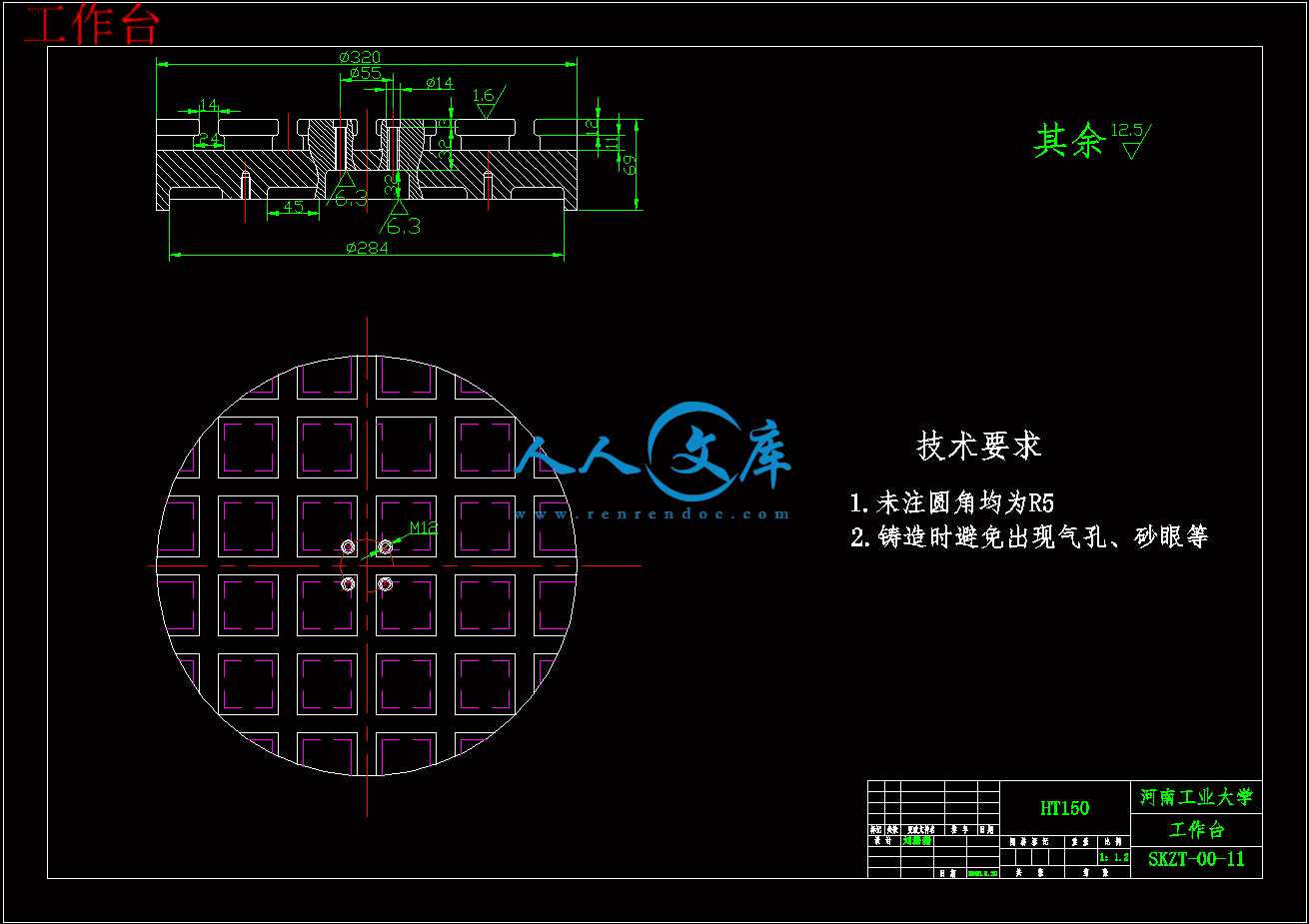
工作台.dwg

摘要.doc

步进电动机驱动的伺服转台的设计说明书.doc

目录.doc

蜗杆.dwg

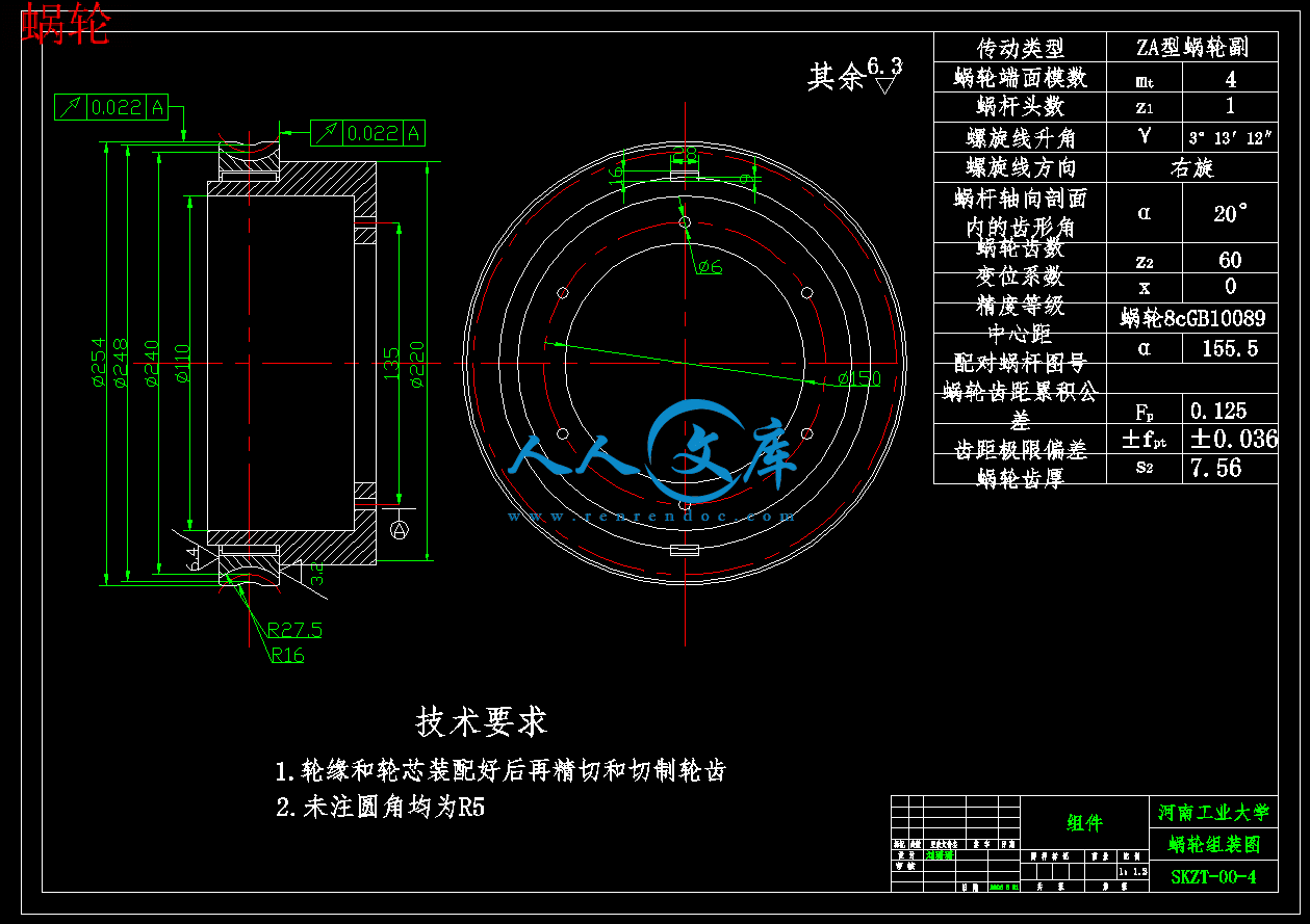
蜗轮.dwg

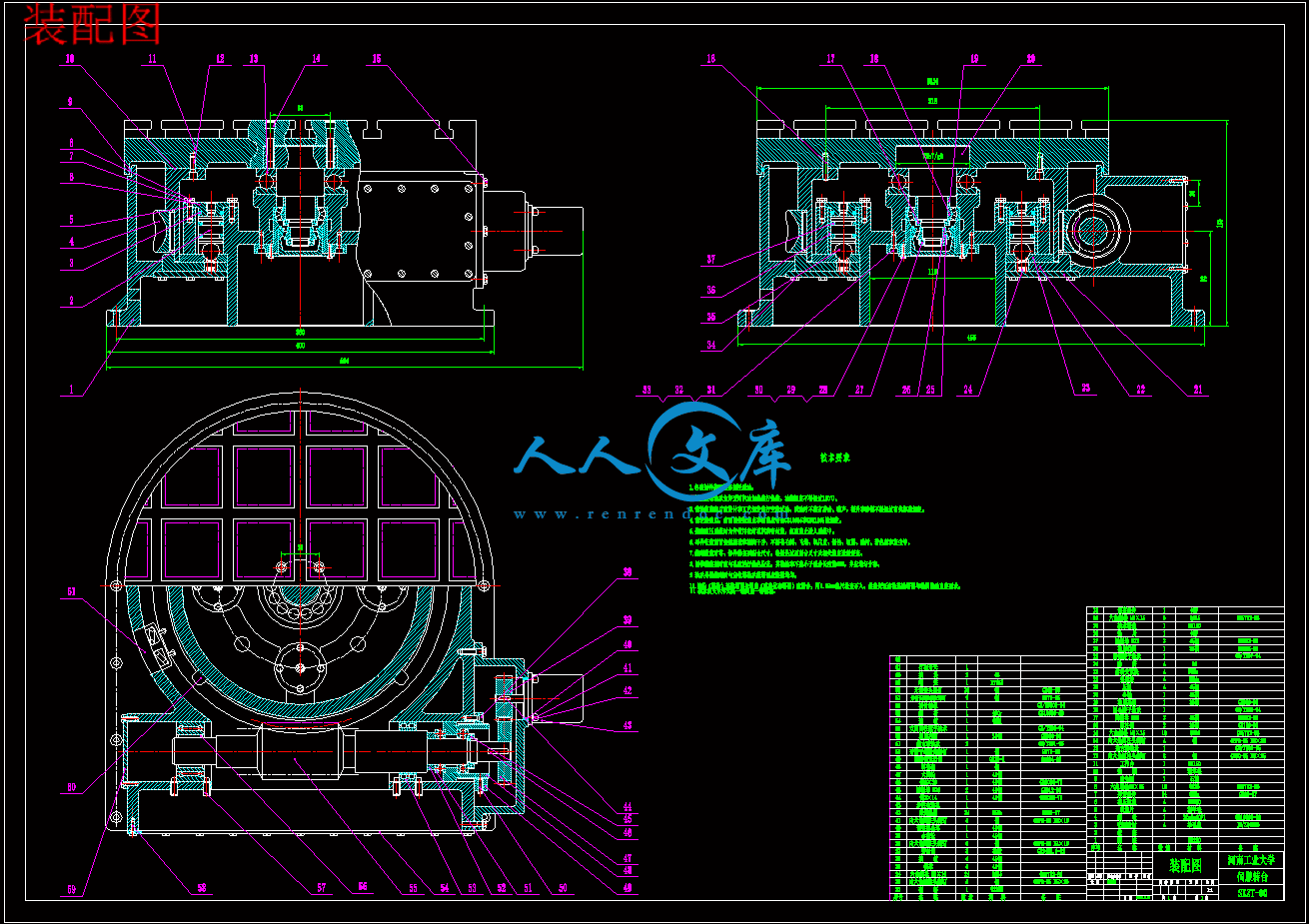
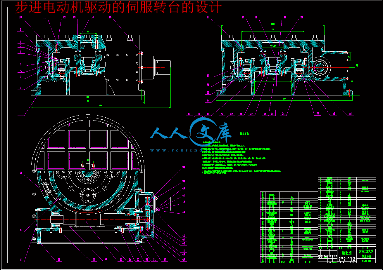
装配图.dwg

装配图.exb

齿轮.dwg


目  录

引言 ……………………………………………………………………………………………………1

1  数控转台的工作原理及其方案论证…………………………………………………2    

1.1 数控转台的工作原理 …………………………………………………………………………2

1.2 方案论证…………………………………………………………………………………………2

1.2.1 转台系统的方案论证………………………………………………………………………2

1.2.2 控制系统的方案论证……………………………………………………………………4

2  机械部分设计……………………………………………………………………………………4

2.1 转台本体设计…………………………………………………………………………………4

2.2 选择电动机……………………………………………………………………………………5

2.2.1 各轴转速的计算……………………………………………………………………………5

2.2.2 计算最大静转矩……………………………………………………………………………5

2.3 齿轮的设计……………………………………………………………………………………6

2.3.1 选择齿轮材料、热处理齿面硬度、精度等级及齿数 ……………………………6

2.3.2 设计计算……………………………………………………………………………………7

2.4 蜗轮蜗杆设计…………………………………………………………………………………9

2.4.1 双导程蜗杆蜗轮副概述 …………………………………………………………………10

2.4.2 蜗轮蜗杆设计计算…………………………………………………………………………11

3  控制部分的设计 ………………………………………………………………………………15

3.1 系统功能与设计要求…………………………………………………………………………15

3.2 方案选择 ………………………………………………………………………………………16

3.2.1 转台系统……………………………………………………………………………………16

3.2.2 步进电动机控制器…………………………………………………………………………16

3.3 系统硬件设计…………………………………………………………………………………17

3.3.1 步进电动机的选择………………………………………………………………………17

3.3.2 脉冲分配器接口电路设计………………………………………………………………17

3.3.3 功率放大器电路…………………………………………………………………………18

3.3.4 8098单片机及其EPROM、RAM系统扩展……………………………………………19

3.3.5 LED显示器与小键盘的扩展……………………………………………………………20

3.4 系统控制与软件编程………………………………………………………………………22

3.4.1用DDA方法产生参考脉冲序列…………………………………………………………22

3.4.2 软件分配器…………………………………………………………………………………29

3.4.3 8279的编程………………………………………………………………………………32

3.4.4 系统总体软件编程…………………………………………………………………………33

小结……………………………………………………………………………………………………36

总结……………………………………………………………………………………………………37

致谢……………………………………………………………………………………………………38

参考文献………………………………………………………………………………………………39


摘要

   现代数控技术的发展日新月异,机床的新结构、新技术不断出现,使机床附件也随之发展迅速。伺服转台在数控机床上的应用越来越多。本次设计的是数控机床上使用的伺服转台,通过在原工作台上安装数控转台,可以实现较高精度的旋转定位。一些难于加工的零件因为有了数控转台,从而使加工过程变得简单。

   数控回转工作台主要应用于铣床等,特别是在加工复杂的空间曲面方面(如航空发动机叶片、船用螺旋桨等),由于回转工作台具有圆周进给运动,易于实现与X、Y、Z三坐标的联动,但需与高性能的数控系统相配套。伺服转台的出现,可以替代原有精度不高的机械转台,伺服转台可以实现高的精度要求,使一些难以达到加工要求的零件很轻松的达到要求.

   此次设计采用的是步进电动机驱动蜗轮蜗杆转动从而带动数控转台转动。采用开环系统回转工作台,其特点为结构简单、控制方便、投资少。采用步进电动机伺服驱动,满足中等精度的数控机床的控制要求。

   此设计中的传动机构主要包括两部分:齿轮传动和蜗轮蜗杆传动。

   齿轮传动是机械传动中最主要的一类传动,它由装在两轴上的主、从动齿轮所组成,通过轮齿间的啮合传递运动和动力。

   蜗杆传动由蜗轮和蜗杆组成,用于传递空间两交错轴之间的运动和动力,通常两轴交错角为90°,该传动广泛应用于各种机器和仪器中。

   本设计的控制部分是由Intel MCS-8098单片机构成的步进电动机通用驱动控制器来控制其运动的。主要由人机接口、参考脉冲与脉冲分配器及功率放大等功能块组成。

   把机械部分和控制部分结合起来,就可以满足步进电动机伺服系统的精度要求。

关键词    数控伺服转台    数空机床附件    传动机构  

   科学技术的迅猛发展使当今世界进入信息化时代,把信息技术融入机电设备中,产生了机电一体化技术。数控机床集计算机技术、电子技术、自动控制、传感测量、机械制造、网络通信技术于一体,是典型的机电一体化产品。其中,数控转台也是一种典型的机电一体化产品.

   本次设计的是数控机床上使用的伺服转台,通过在原工作台上安装数控转台,可以实现较高精度的旋转定位。一些难于加工的零件因为有了数控转台,从而使加工过程变得简单。

  数控回转工作台主要应用于铣床等,特别是在加工复杂的空间曲面方面(如航空发动机叶片、船用螺旋桨等),由于回转工作台具有圆周进给运动,易于实现与X、Y、Z三坐标的联动,但需与高性能的数控系统相配套。

   本次设计说明书共分为三章,主要包括数控转台的工作原理及其方案论证、机械部分的设计和控制部分的设计等内容。

   通过对有关资料的收集和查阅,机械部分我们选用步进电动机驱动蜗轮蜗杆来带动伺服转台的转动。控制部分是由Intel MCS-8098单片机构成的步进电动机通用驱动控制器来控制其运动的。

   本次设计可以实现的功能有:在机床的原工作台上使用;由步进电动机驱动;由单片机控制;实现三种脉冲分配方式的控制;系统有关参数可通过LED显示器显示出来;转台能够实现顺、逆两个方向的转动,转角范围不定;可实现匀速、加速控制以及点控制;转台最高转速达100°/s,定位精度为2′。

   通过本次设计,使我更加地了解到当前制造业发展的迅速,同时,可以巩固在校所学到的知识,给我们以后的工作奠定了坚实的基础。由于时间仓促和本人的水平有限,设计中的错误和不妥之处在所难免,恳请老师和同学们批评指正。

1  数控转台的工作原理及其方案论证

1.1 数控转台的工作原理

   数控机床是一种高效率的加工设备,当零件被装夹在工作台上以后,为了尽可能完成多工序或者全部完成一次装夹后所有工序的加工,以扩大工艺范围和提高机床利用率。除了要求机床有X、Y、Z三个坐标轴直线运动之外,还要求工作台在周围方向有进给运动和分度运动。

   通常回转工作台可以实现上述运动,用以进行圆弧加工或与直线联动进行曲面加工,以及利用工作台精确的自动分度,实现箱体在零件各个面的加工。在自动换刀多工序数控机床,加工中心上,回转工作台已成为不可缺少的部件,为快速更换工件,带有托板交换装置的工作台应用也越来越多。

   数控机床回转工作台主要有两种:数控进给回转工作台和分度回转工作台,其工作台面的形式有带托板交换装置和不带托板交换装置两种。

   数控回转工作台的主要功能有两个:一是工作台进给分度运动,即在非切削时。装有工件的工作台在整个圆周(360o范围内)进行分度旋转;二是工作台作圆周方向进给运动,即在进行切削时,与X、Y、Z三个坐标轴进行联动,加工复杂的空间曲面。

   数控回转工作台主要应用于铣床等,特别是在加工复杂的空间曲面方面(如航空发动机叶片、船用螺旋桨等),由于回转工作台具有圆周进给运动,易于实现与X、Y、Z三坐标的联动,但需与高性能的数控系统相配套。

1.2 方案论证

   此次设计采用的是步进电动机驱动蜗轮蜗杆转动从而带动数控转台转动。采用开环系统回转工作台,其特点为结构简单、控制方便、投资少。采用步进电动机伺服驱动,满足中等精度的数控机床的控制要求。

   本次设计包括两大方面内容:转台系统设计和步进电动机控制设计。

1.2.1转台系统的方案论证

内容简介:
毕业设计(论文)河南工业大学毕业设计(论文)参考文献译文学院名称: 机电工程学院 专业班级: 学生姓名: 学 号: 译文出处:机电与数控专业英语数控专业英语 2006年5月20日NC and CNC1. The history NC and CNC development Numerical control (NC)machining process in which the operations are executed automatically in sequences as specified by the program that contains the information for the tool movements. The NC concept was proposed in the late 1940s by John parsons of Traverse city .Michingan .parsons recommended a method of automatic machine control that would guide a milling cutter to produce a “thruaxis carve “ in order to generate smooth profiles on work pieces. In 1949, the V.S Air Force awarded parsons a contract to develop a new type of machine tool that would be able to speed up production methods .parsons commissioned the Massachusetts.Institute of technology to develop a practical implementation of his concept . scientists and engineers at M.I.T .built a control system for a twoaxis milling machine that used a perforated paper tape as the input media .in a short of time , all major machine tool manufacturers were producing some machines with NC, but it was not until the late 1970s that computer-based NC became widely used . NC mature as an automation technology when inexpensive and powerful microprocessors replaced hard-wire logic-making computer-based NC systems2. the applications of NC/CNCSince its introductions, NC technology has found many applications, including lathes and turning centers, milling machines and machining centers, punches, electrical discharge machines(EDM),flame cutters, grinders, and testing and inspection equipment. The mast complex CNC machine tools are the turning centers ,the control panel on the right can be swiveled by the operator and Horizontal machining center, equipped with an automatic tool changer. Tool magazines can store 200cutting tools3. The Advantages and Disadvantages of CNC Machines(1) CNC machines have many advantages of CNC machines There is a possibility of performing multiple operations on the same machine in one setup Because of the possibility of simultancous multi-axis tool movement , special profile tools are not necessary to cut unusual part shapes The scrap rate is significantly reduced because of the precision of the CNC machine and lesser operator impact It is easy to incorporate part design changes when CAD/CAM systems are used. It is easer to perform quality assurance by a spot-check instead of checking all parts. Production is significantly increased.(2) CNC machines also have some disadvantages they are quite expensive they have to be programmed, set up, operated and maintained by highly skilled personalobviously, CNC machines have more advantages than disadvantages, The companies that adept technology increase their competitive edge. As always with new technology ,The cast per CNC unit is being cut further and more companies can afford CNC equipment, which enables them to answer the increasingly strong requirements for production speed and quality that competitive markets demand, In the future the broader use of machines will be one of the best ways to enhance automation in manufacturing.4. The construction of CNC machines. CNC machine tools are complex assemblies. However, in general ,any CNC machine tool consists of the following units: Computer Control systems Drive motors Tool changersAccording to the construction of CNC machine tools, CNC machines work in the following manner. The CNC machine language, which is a programming language of binary notation used on computer ,not on CNC machines. .When the operator starts the execution cycle ,the computer translates binary codes into electronic pulses which are automatically sent to the machines power units. The control units compare the number of pulses sent and received. . When the motors receive each pulse ,they automatically transform the pulses into drive the spindle and lead screw, causing the spindle rotation and slide or table movement. The part on the milling machine table or the tool in the lathe turret is driven to the position specified by the program. Computer As with all computers. The CNC machine computer works on a binary principal using only two characters 1 and 0 ,for information processing precise time impulses form the circuit. Special built-in software compiles the program into machine language and the machine moves the tool by its servomotors. Modern CNC machines use 32-bit processors in their computer that allow fast and accurate processing of informationControl systems There are two types of control systems on NC/CNC machines: open loop and closed loop. The type of control used determines the overall accuracy of the machineDrive motors The drive motors control the machine slide movement on NC/CNC equipment. They come in four basic type: Stepper motors PC servomotors AC servomotors Fluid servomotors Tool changers Tool changers may be equipped for either random or sequential selection.In random tool selection, there is no specific pattern of tool selection. On the machining center, when the program calls for the tool, it is automatically.Indexed into waiting position, where it can be retrieved by the tool-handling device. On the turning center, the turret automatically rotates, bringing the tool into position.译文:数字控制与计算机数字控制1.数字控制与计算机数字控制的发展历史数字控制是安着含有机床(刀具)运动信息程序所指定的顺序自动执行操作的加工过程.数控这一词概念是由密歇根州特拉化城的约憨帕森于20世纪四十年代后期提出的,为了在工件上加工光滑的轮廓,帕森提出了一种自动的机床控制方式,它能够引导铣床刀具加工出一种“过轴曲线”1949年,美国空军与帕森签署了合同,要求开发一种能够提高生产率的新型机床.帕森委托麻省理工学院(MIT)来开发一种新概念机床,麻省理工学院的科学家和工程师研制出了一种用穿孔纸带作为输入媒介的二轴联动铣床控制系统.在教短的时间内,但是所有主要铣床生产商都生产了一些数控机床,但直到20世纪七十年代后期,基于计算机的数字控制才得到广泛的使用.只有价格低廉功能强大的微处理芯片代替了计算机数控系统中的硬线性逻辑发生器后,NC才真正成为一门自动化技术2.数字控制与计算机数字控制的应用数控技术自创立以来就得到了广泛的应用,包括车床和车削中心,铣床和加工中心,冲床,电火花加工机床.线切割机床,磨床以及测试检测装置等,最复杂的计算机数控机床是车削中心,一个具有十轴位的刀架能进行快速换刀的现代车削中心,立式加工中心,刀具库在机床的左边.右边的控制面扳可由操作者通过转臂转动,以及卧式加工中心,通过按下按钮每把刀可在数秒内定位,配有自动换刀系统,刀具库储备有200把切削刀具3.计算机数控机床的优缺点计算机数控机床与传统机床相比具有很多优点,它们是:在同一机床上,一次安装可完成多个操作由于机床可实现多轴联动,切削非常规的零件形状时,可以不必使用成形刀具.由于计算机数控机床的精度高,受操作者影响小,废品率明显降低.采用CAD/CAM系统后,对零部件装配设计的修改就变得很容易.通过轴检代替全检,质量更容易保证.生产率明显提高. 计算机数控机床也有一些缺点:价格昂贵.必须由高级技术人员来编程,安装,操作与维护.显然,计算机数控机床利大于弊.已经采用计算机数控技术的企业正在提高他们的竞争力.随着新技术的采用,每台计算机数控单元的价格正在进一步降低,更多的公司能够买得起计算机数控装备,使其能够满足竞争市场对产品生产速度和质量日益增强的需求,将来计算机数控机床的广泛使用成为制造业提高自动化程度的最佳选择之一.4.计算机数控机床的结构.CNC机床结构较为复杂,一般来说,任何CNC机床都包含以下几个单元: 计算机 控制系统 驱动电机 换刀机构根据CNC机床的结构,CNC机床以下列方式工作: CNC机床语言是一种用在计算机上的二进制符号编程语言,而不是用在CNC机床上, 当操作者开始执行循环时,计算机将二进制代码翻译成电脉冲,并自动地送给机床的控制单元.控制单元将发出的脉冲与接收的脉冲数加以比较, 电动机每接收一个脉冲,就自动地将脉冲信号转换成旋转信号,从而驱动主轴和丝杠,带动主轴旋转和拖校或工作台的移动,铣床工作台上的零件或车床转塔刀架上的刀具被驱动到程序指定的位置.计算机.CNC机床的计算机也是根据二进制原理,只有两个 1和0作为电路的时间脉冲速度信息,机器内的特殊软件将程序编译为机器语言,由伺服电动机带动刀具工作,现代CNC机床的计算机使用32位处理器可以实现信息的快速准确处理.控制系统. 在NC/CNC机床里有两种类型的控制系统:开环和闭环,控制环的类型决定机床的整体精度.驱动电机驱动电机控制NC/CNC设备上拖扳的运动,它们有四种类型: 步进电动机 直流伺服电机 交流伺服电机 液压伺服电机换刀机构 换刀机构有随机换刀和顺序换刀,在随机换刀中,没有刀具选择的具体路径.对于加工中心,当程序调用刀具时,刀具处理装置自动检索到处于等待位置的刀具,对于车削中心,回转刀架能自动地旋转,将刀具带到指定的位置Machines using NC Early machine tools designed so that the operator was standing in front of the machine while operating the controls. This design is no longer necessary, since in NC the operator no longer control the machine tool movements. On conventional machine tools. Only about 20percent of the time was spent removing material. With the addition of electronic controls, actual time spent removing metal has increased to 80percent and even higher. It has also reduced the amount of time required to bring the cutting tool into each machining position. In the past, machine tools were kept as simple as possible in order to keep their costs down. Because of the ever-rising cost of labor, better machine tools, complete with electronic controls, were developed so that industry would produce more and better goods at prices which were competitive with those of offshore industries. NC is being used on all types of machine tools, from the simplest to the most complex. The most common machine tools are the single-spindle drilling machine, lathe, milling machine ,turning centers ,and machining center.1. single-spindle Drilling Machine. One of the simplest numerically controlled machine tools is the single-spindle drilling machine. Most drilling machines are programmed on three axes:a. The x-axis controls the table movement to the right and left.b. The y-axis controls the table movement toward or away from the column.c. The I-axis controls the up or down movement of the spindle to drill holes to depth.2. Lathe The engineer lathe, one of the most productive machine tools, has always been a very efficient means of producing round parts. Most lathes are programmed on two axes:a. The x-axis controls the cross motion (in or out) of the cutting tool.b. The z-axis controls the carriage travel toward or away from the headstock.3. Milling machineThe milling machine has always been one of the most versatile machine tools used in industry. Operations such as milling, contouring, gear cutting, drilling, boring, and reaming are only a few of the many operations which can be performed on a milling machine. The milling machine can be programmed on three axes:a. The x-axis controls the table movement left or right.b. The y-axis controls the table movement toward or away from the column.c. The z-axis controls the vertical (up or down) movement of the knee or spindle.4. Turning center Turning center were developed in the mid-1960s after studies showed that about 40percent of all metal cutting operations were performed on lathes. These numerically controlled machines are capable of greater accuracy and higher production rates than were possible on the engine lathe. The basic turning center operates on only two axes:a. The x-axis controls the cross motion of the turret head .b. The z-axis controls the lengthwise travel (toward or away from the headstock) of the turret head.5. Machining center.Machining centers were developed in the 1960s so that a part did not have to be moved from machine to machine in order to perform various operations. These machines greatly increased production rates because more operations could be performed on a work piece in one setup. There are two main types of machining centers, the horizontal and the vertical spindle types.a. The horizontal spindle machining center operates on three axes:a).The x-axis controls the table movement .(left or right).b). The y-axis controls the vertical movement (up or down) of the spindle.c).The z-axis controls the horizontal movement (in or out ) of the spindle.B .The vertical spindle machining center operates on three axes: a).The x-axis controls the table movement left or right. b).The y-axis controls the table movement toward or away from the column. c).The z-axis controls the vertical movement (up or down) of the spindle.数控机床老式机床是按操作工站立在机床前进行操作来设计的,现在不需要这种设计了,因为操作工并不直接操纵数控机床的运行.在传统机床上加工时,只有约20%的时间用于切削材料,随着电控设备的加入,实际切削材料的时间已增至80%以上,并且缩短了将刀具送入每个加工位置的时间.过去,人们尽量使机床结构简单,以便降低成本,由于劳动成本日益上涨.人们研制出性能更好的机床,并能有电控设备,这样企业可以生产更多的价格较低的产品,以和国际上的产品相竞争.从最简单到最复杂的机床都会用到数控技术,最常见的机床有:单轴钻床.卧式车床.铣床.车削中心及加工中心.1. 单轴钻床.单轴钻床是最简单的数控机床之一,多数数控钻床可以在三个坐标轴上编程.(1)X轴控制工作台左右运动.(2) Y轴控制工作台靠近或离开立柱.(3) Z轴控制主轴上下运动,确定孔的加工深度.2. 卧式车床.卧式车床是生产效率最高的机床之一,它是加工回转体零件时非常有效的工具,大部分数控车床可在两个坐标轴上编程.(1) X轴控制刀具横向运动(切入.切出).(2) Z轴控制机床拖板靠近或离开主轴箱.3. 铣床.铣床是工业生产加工方式最多的机床之一,像铣削.成形加工.齿加工.钻.镗.铰等只是可在铣床上进行的一少部分加工,数控铣床可以在三个坐标轴上编程.(1) X轴控制工作台左右运动.(2) Y轴控制工作台靠近或离开立柱.(3) Z轴控制升降台或主轴垂直(上下)运动.4. 车削中心.研究表明:整个金属材料的切削操作大约40%是在车床上进行的,早在20世纪60年代中期,人们就开始研究车削中心.这种数控机床具有比普通车床更高的加工精度和生产效率,一般数控车削中心仅在两轴上工作:(1) X轴控制转搭头横向运动.(2) Z轴控制刀架纵向运动(靠近或离开主轴箱).5. 加工中心.加工中心是在20世纪60年代发展起来的.有了加工中心,人们不必把零件从一台机床转移到另一台机床就能完成各种加工.由于工件经过一次装夹后便能进行各种加工,所以大大提高了生产效率. 加工中心主要有两类:加卧式工中心和立式加工中心A: 卧式加工中心可在三个坐标轴上工作.(1) X轴控制工作台左右运动.(2) Y轴控制主轴垂直(上下)运动.(3) Z轴控制主轴水平运动 (切入.切出).B: 立式加工中心可在三个坐标轴上工作.(1) X轴控制工作台左右运动.(2) Y轴控制工作台靠近或离开立柱.(3) Z轴控制主轴垂直(上下)运动.摘要现代数控技术的发展日新月异,机床的新结构、新技术不断出现,使机床附件也随之发展迅速。伺服转台在数控机床上的应用越来越多。本次设计的是数控机床上使用的伺服转台,通过在原工作台上安装数控转台,可以实现较高精度的旋转定位。一些难于加工的零件因为有了数控转台,从而使加工过程变得简单。数控回转工作台主要应用于铣床等,特别是在加工复杂的空间曲面方面(如航空发动机叶片、船用螺旋桨等),由于回转工作台具有圆周进给运动,易于实现与X、Y、Z三坐标的联动,但需与高性能的数控系统相配套。伺服转台的出现,可以替代原有精度不高的机械转台,伺服转台可以实现高的精度要求,使一些难以达到加工要求的零件很轻松的达到要求. 此次设计采用的是步进电动机驱动蜗轮蜗杆转动从而带动数控转台转动。采用开环系统回转工作台,其特点为结构简单、控制方便、投资少。采用步进电动机伺服驱动,满足中等精度的数控机床的控制要求。此设计中的传动机构主要包括两部分:齿轮传动和蜗轮蜗杆传动。齿轮传动是机械传动中最主要的一类传动,它由装在两轴上的主、从动齿轮所组成,通过轮齿间的啮合传递运动和动力。蜗杆传动由蜗轮和蜗杆组成,用于传递空间两交错轴之间的运动和动力,通常两轴交错角为90,该传动广泛应用于各种机器和仪器中。本设计的控制部分是由Intel MCS-8098单片机构成的步进电动机通用驱动控制器来控制其运动的。主要由人机接口、参考脉冲与脉冲分配器及功率放大等功能块组成。把机械部分和控制部分结合起来,就可以满足步进电动机伺服系统的精度要求。关键词 数控伺服转台 数空机床附件 传动机构 Title Step-by-steps the direct motor drive servoturnplate design AbstractThe modern numerical control technology development changes with each new day, the engine bed new structure, the new technology appear unceasingly, cause the engine bed appendix to be also rapid along with it development. The servo turnplate are more and more many on numerical control engine bed application. This design the servo turnplate which is on the numerical control engine bed uses, through installs the numerical control turnplate on the original work table, may realize the high precision revolving localization. Some difficulty with process because the components had the numerical control turnplate, thus causes the processing process to become simple.The numerical control rotary table mainly applies in the milling machine and so on, specially in processing complex space-like surface aspect (for example aircraft engine leaf blade, ship with propeller and so on), because the rotary table has the circumference feed motion, easy to realize with X, Y, the Z three coordinates linkages, but must form a complete set with the high performance numerical control system. The servo turnplate appearance, may substitute the original precision not high mechanical turnplate, the servo turnplate may realize the high precision request, enables some to achieve with difficulty the processing request the components very relaxed meet the requirements.Thus this d
温馨提示:
1: 本站所有资源如无特殊说明,都需要本地电脑安装OFFICE2007和PDF阅读器。图纸软件为CAD,CAXA,PROE,UG,SolidWorks等.压缩文件请下载最新的WinRAR软件解压。
2: 本站的文档不包含任何第三方提供的附件图纸等,如果需要附件,请联系上传者。文件的所有权益归上传用户所有。
3.本站RAR压缩包中若带图纸,网页内容里面会有图纸预览,若没有图纸预览就没有图纸。
4. 未经权益所有人同意不得将文件中的内容挪作商业或盈利用途。
5. 人人文库网仅提供信息存储空间,仅对用户上传内容的表现方式做保护处理,对用户上传分享的文档内容本身不做任何修改或编辑,并不能对任何下载内容负责。
6. 下载文件中如有侵权或不适当内容,请与我们联系,我们立即纠正。
7. 本站不保证下载资源的准确性、安全性和完整性, 同时也不承担用户因使用这些下载资源对自己和他人造成任何形式的伤害或损失。
提示  人人文库网所有资源均是用户自行上传分享,仅供网友学习交流,未经上传用户书面授权,请勿作他用。
关于本文
本文标题:步进电动机驱动的伺服转台的设计【5张CAD图纸】【优秀】
链接地址:https://www.renrendoc.com/p-275040.html

官方联系方式

2:不支持迅雷下载,请使用浏览器下载   
3:不支持QQ浏览器下载,请用其他浏览器   
4:下载后的文档和图纸-无水印   
5:文档经过压缩,下载后原文更清晰   
关于我们 - 网站声明 - 网站地图 - 资源地图 - 友情链接 - 网站客服 - 联系我们

网站客服QQ:2881952447     

copyright@ 2020-2025  renrendoc.com 人人文库版权所有   联系电话:400-852-1180

备案号:蜀ICP备2022000484号-2       经营许可证: 川B2-20220663       公网安备川公网安备: 51019002004831号

本站为文档C2C交易模式,即用户上传的文档直接被用户下载,本站只是中间服务平台,本站所有文档下载所得的收益归上传人(含作者)所有。人人文库网仅提供信息存储空间,仅对用户上传内容的表现方式做保护处理,对上载内容本身不做任何修改或编辑。若文档所含内容侵犯了您的版权或隐私,请立即通知人人文库网,我们立即给予删除!