外文翻译--工业机器人.doc

QKA1219数控管螺纹车床主轴箱传动设计【5张CAD图纸】【缺装配图】

收藏

压缩包内文档预览:
预览图 预览图 预览图 预览图 预览图 预览图 预览图 预览图 预览图
编号:283119    类型:共享资源    大小:2.94MB    格式:RAR    上传时间:2014-05-16 上传人:上*** IP属地:江苏
40
积分
关 键 词:
QKA1219 数控 管螺纹车床 主轴箱 传动设计 cad图纸
资源描述:

QKA1219数控管螺纹车床主轴箱传动设计

31页 12000字数+说明书+任务书+开题报告+外文翻译+5张CAD图纸

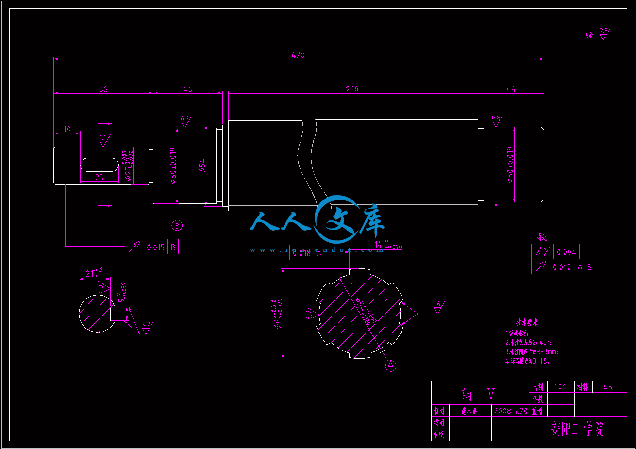
5轴A3.dwg

QKA1219数控管螺纹车床主轴箱传动设计开题报告.doc

QKA1219数控管螺纹车床主轴箱传动设计说明书.doc

任务书.doc

内摩擦片.dwg

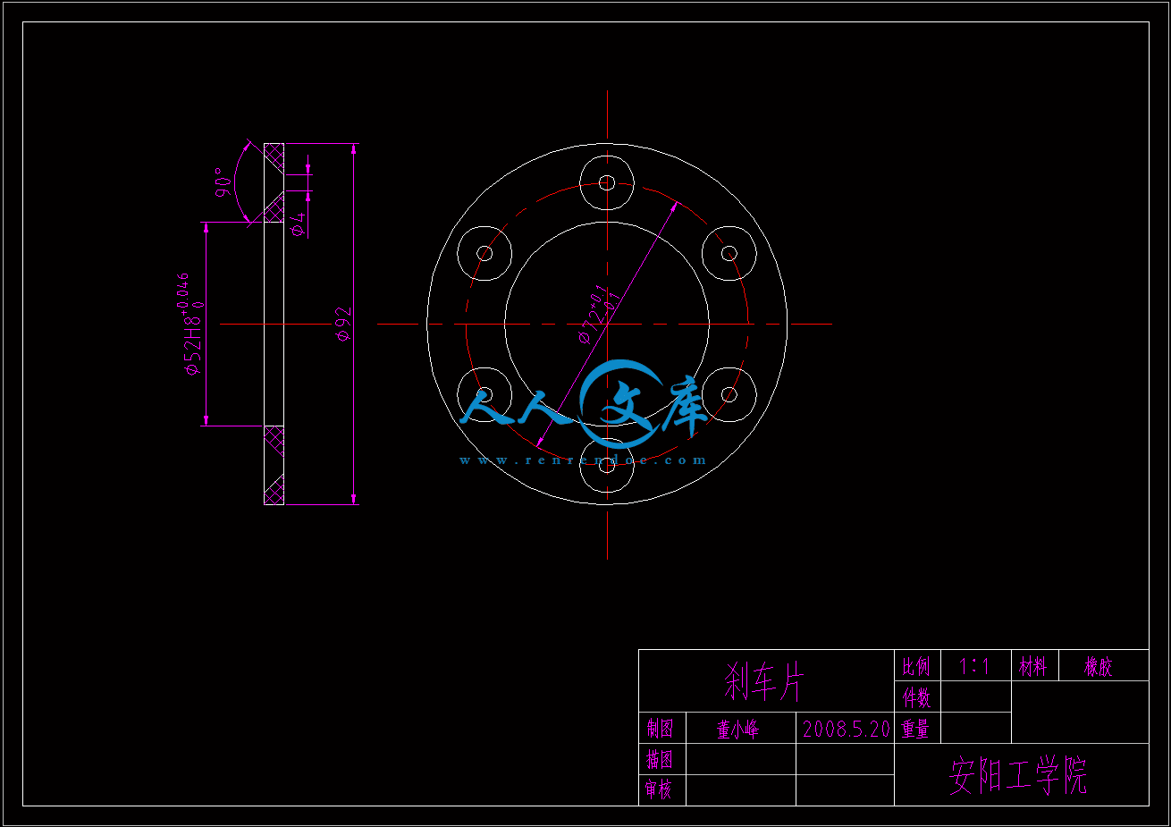
刹车片.dwg

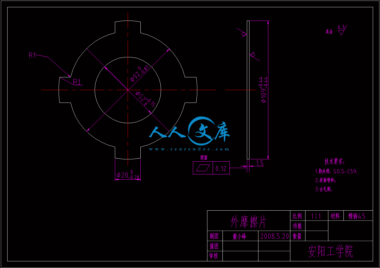
外摩擦片.dwg

外文翻译--工业机器人.doc

封皮.doc

摘要.doc

目录.doc

答辩申请表.doc

英文皮.doc

2轴.dwg

数控管螺纹车床主轴箱传动设计

摘要  QKA1219数控管螺纹车床是安阳鑫盛机床厂设计研发并生产的。该机床主要为油田管螺纹的车削而开发,而且还适合各类管螺纹的车削,同时还可以作为普通车床使用,适合加工形状复杂的轴、套、盘类零件。

  由于该机床属于半闭环控制的数控车床,比起普通车床省去了进给箱和溜板箱等机械结构,主轴箱和刀架之间的内联系传动链由数控系统和伺服系统代替。所以,主轴箱的功用不仅仅是支承主轴并把动力经变速传动机构场传递给主轴,还要考虑车床的数控化等要求,这就使得主轴箱的设计显得极为主要。

  本论文的课题是QKA1219数控管螺纹车床的主轴箱传动设计。主要从传动方案的论证和选择,结构网的选择和转速图的拟定等方面来阐述这个课题。

关键词:数控  机床  主轴箱  校核?? 管螺纹  

Design of headstock of QkA1219 numerical control lathe which machining pipe thread

Abstract  QKA1219 pipe thread machining numerical control lathe is designed and produced by AnYang XinSheng cooperation. This kind of lathe is mainly developed for oil fields to machining pipe thread. Besides, it also can machine other kind of parts as a normal lathe.

Being a semi-loop controlled NC lathe, this lathe have no feedbox and apron compared with normal lathe, the drive chain between headstock and tool slide is replaced by CN and servo system, so, the purpose of the headstock is not as it in a normal one, and we also should consider of other aspects, hence, the design of headstock becoming very important.

This paper is mainly about this lathe’s headstock drive design. And I show my point mainly from the choose of speed diagram, choose and testimony of the design manner and so on.

Key words  NC  Machine tools  Spindle box   Check  pipe thread.


目录

第一章 绪论…………………………………………………………………………………1

1.1  课题的背景及意义……………………………………………………………1

1.2  数控机床国内外发展现状…………………………………………………………2

1.3  本论文主要研究内容……………………………………………………………4

第二章 主轴箱参数的确定……………………………………………………………5

2.1车床的参数和规格…………………………………………………………5

2.2公比和最大相对转速损失率………………………………………………5

2.3动力参数的确定和电机的选择……………………………………………5

第三章 传动方案的设计………………………………………………………7

3.1传动顺序组的安排………………………………………………………………7

3.2 传动结构式和结构网的选择…………………………………………………11

   3.3转速网的拟订…………………………………………………………………12

第四章 传动件的估计和确定…………………………………………………14

4.1 带轮传动的确定………………………………………………………………14

4.2 齿轮齿数的确定………………………………………………………………18

4.3 传动轴的估算…………………………………………………………………18

4.4 齿轮模数的估算………………………………………………………………20

第五章 传动结构简图的设计…………………………………………………23

5.1 结构设计的要求………………………………………………………………23

5.2 结构细节的内容………………………………………………………………24

5.3主轴箱传动结构简图………………………………………………………………26

结论………………………………………………………………………………………27

致谢……………………………………………………………………………………………28

参考文献…………………………………………………………………………………29

本课题研究的主要内容是QKA1219数控管螺纹车床的主轴箱传动部分。

  该机床主要为油田管螺纹的车削而开发,且适合于各类管螺纹的车削,还可作普通数控车床使用。

该机床属于半闭环控制系统的简式数控管螺纹车床,可以加工以各种曲线为母线的连续的回转体,加工分辨为0.001mm。可加工圆柱、锥面螺纹,以及圆柱与锥面连续连接螺纹、端面螺纹。具有刀具自动补偿功能,具有坯料循环、加工螺纹循环、切槽循环。可任意设定绝对零点。适合多品种、中小批量的轮番加工,工艺适应性强、效率高,成品一致性好。编程容易,操作简单,是理想中的中型机械加工设设备。

QKA1219数控管螺纹车床是将CW系列车床进行数控改造而成的,引进了液压系统从而可以实现8级转速中的4级变速的自动化,由于引进了伺服系统和数控系统,实现了机床的数控化,与普通机床相比省了进给箱和溜板箱,不仅提高了机床的加工精度,而且大大减少了机械设计的繁杂。它与普通机床的具体不同之处在于:主轴箱的运动不再传递给进给箱,而是直接传递给一个脉冲发生器,从而省略了机械内联系传动链,脉冲发生器发出的脉冲被送到脉冲处理器,并经过由数控系统传来的数控编程指令相应的处理,最后到达控制纵向和横向运动的伺服电动机,这样就可以加工出各种复杂形状的轴类零件;但要加工螺纹,还要在加工过程中不乱扣,引进一个脉冲相位处理器就可以实现这个功能。

本课题的主要任务就是利用引进的液动系统来实现主轴箱的4级自动换挡,改进机床的机械结构,实现整个机床的数控化,从而使机床获得较高的生产效率和加工表面质量。

第二章 主轴箱参数的确定

2.1车床的参数和规格

表2.1主要规格

加工最大管子直径主轴通孔直径床身上最大回转直径刀架最大回转直径两顶尖距离最大车削长度

190mm200mm770mm480mm750/1000/1500mm550/800/1300mm


  表2.2轮廓尺寸要求

规格长度宽度高度净重

7500  1000  15002912  3227  3612171517453.7    3.9    4.2

2.2 公比和最大相对转速损失率

  由已知主轴的最大转速和最小转速分别为450r/min 和90r/min ,那么可以知道主轴箱的转速比:

                                      (2-1)

  又因为主轴的转速级数z=8,那么由:

                                               (2-2)

        得          

最大相对转速损失率为:

%                              (2-3)

2.3动力参数的确定和电机的选择

机床主运动的功率,包括切削功率 空转功率损失和附加机械摩擦损失三部分。

进行切削加工时,要消耗切削功率。QKA数控管螺纹车床是专用车床,但也可以当作普通车床使用,所以切削功率与车床的刀具材料、工件材料和切削用量的大小有关。本车床所用的刀具材料为中低碳钢,由公式:


内容简介:
Industrial robotOutline of industrial robotIn practical usage, an industrial robot is a mechanical device that performs automated physical tasks, either according to direct human supervision, a pre-defined program or, a set of general guidelines using artificial intelligence techniques. Robots are typically used to do the tasks that are too dirty, dangerous , difficult, repetitive or dull for humans.An industrial robot is officially defined by ISO as an automatically controlled, reprogrammable , multipurpose manipulator programmable in three or more axes. The field of industrial robotics may be more practically defined as the study, design and use of robot systems for manufacturing (a top level definition relying on the prior definition of robot).Typical applications of industrial robots include welding, painting, ironing, assembly, pick and place, palletizing, product inspection, and testing, all accomplished with high endurance, speed, and precision. Fig.13.1 illustrates industrial robots are doing vehicle underbody assembly.The basic terminology of robotic systems is introduced in the following:(1)A robot is a reprogrammable, multifunctional manipulator designed to move parts, materials, tools, or special devices through variable programmed motions for the performance of a variety of different task. This basic definition leads to other definitions, presented in the following paragraphs that give a complete picture of a complete picture of a robotic system.(2) Preprogrammed locations are paths that the robot must follow to accomplish work. At some of these locations, the robot will stop and perform some operation ,such as assembly of parts, spray painting, or welding. These preprogrammed locations are stored in the robots memory and are recalled later for continuous operation. Furthermore, these preprogrammed locations, as well as other program data, can be changed later as the work requirements change. Thus, with regard to this programming feature, an industrial robot is very much like a computer , where data can be stored and later recalled and edited.(3)The manipulator is the arm of the robot. It allows the robot to bend , reach , and twist. The manipulators axes, also called the degrees of freedom of the robot ,provide this movement. A robot can have from 3 to 16 axes. The term degrees of freedom will always relate to the number of axes found on a robot.(4) The tooling and grippers are not part of the robotic system itself;rather, they are attachments that fit on the end of the robots arm. These attachment connected to the end of the robots arm allow the robot to lift parts, spot-weld, paint, arc-weld, drill, deburr, and do a variety of tasks, depending on what is required of the robot.(5) The robotic system can also control the work cell of the operating robot. The work cell of the robot is the total environment in which the robot must perform its task. Included within this cell may be the controller, the robot manipulator, a worktable, safety features, or a conveyor. All the equipment that is required in order for the robot to do its job is included in the work cell. In addition, signals from outside devices can communicate with the robot in order to tell the robot when it should assemble parts, pick up parts, or unload parts to a conveyor.2 Industrial robot types & featuresThe most commonly used robot configurations for industrial automation include articulated robots(The first and most common), SCARA robots and gantry robots(Cartesian Coordinate robots, or x-y-z robots). In the context of general robotics, most types of industrial robots would fall into the category of robot arms (inherent in the use of the word manipulator in the above-mentioned ISO standard).Industrial robots exhibit varying degrees of autonomy. Robots are programmed to faithfully do specific actions over again without variation and with a high degree of accuracy. These actions are determined by programmed routines that specify the direction, acceleration, velocity, deceleration, and distance of coordinated motions. Other industrial robots are much more flexible as to the orientation of the object on which they are operating or even the task that has to be performed on the object itself, which the robot may even need to identify. For example, for more precise guidance, robots often contain machine vision sub-systems acting as their “eyes”, linked to powerful computers or controllers. Artificial intelligence, or what passes for it, is becoming an increasingly important factor in the modern industrial robot.3 History of Industrial RoboticsThe first company to produce an industrial robot was Unimation, founded by Joseph F.Engelberger in 1962, with the basic inventions of George Devol. Unimation robots were also called programmable transfer machines since their main use at first was to transfer objects from one point to another, less than a dozen feet or so apart . They used hydraulic actuators and were programmed in joint coordinates, i.e. the angles of the various joints were stored during a teaching phase and replayed in operation. For some time Unimations only competitor was Cincinnati Milacron Inc. of Ohio. This changed radically in the late 1970s when several big Japanese conglomerates began producing similar industrial robots. Unimation had obtained patents in the United States but not in Japan, so their designs were copied and then improved upon in that country.In 1969 Victor Scheinman at Stanford University invented the Stanford arm, an all-electric, 6-axis articulated robot designed to permit an arm solution. This allowed the robot to accurately follow arbitrary paths in space and widened the potential use of the robot to more sophisticated application such as assembly and arc welding. Sheinman sold his design to Unimation who further developed it with support from General Motors and later sold it as the Programmable Universal Machine for Assembly (PUMA).In 1973 KUKA Robotics built its first industrial robot, known as FAMULUS, this is the first articulated industrial robot to have six electromechanically driven axes.Interest in industrial robotics swelled in the late 1970s and many companies entered the field, including large firms like General Electric, and General Motors(which formed joint venture FANUC Robotics with FANUC LTD of Japan). US start-ups included Automatix and Adept Technology, Inc. At the height of the robot boom in 1984,Unimation was acquired by Westinghouse Electric Corporation for 107 million US dollars. Westinghouse sold Unimation to Staubli Faverges SCA of France in 1988. Staubli was still making articulated robots for general industrial and clean room applications as of 2004 and even bought the robotic division of Bosch in late 2004.Eventually the deeper long-term financial resources and strong domestic market enjoyed by the Japanese companies prevailed, their robots spread all over the globe. Only a few non-Japanese companies managed to survive in this market, including Adept Technology, Staubli-Unimation, the Swedish-Swiss company ABB(ASEA Brown-Boveri), the Austrian manufacturer igm Robotersysteme AG and the German company KUKA Robotics.4.Components of Industrial Robot The robotic system has three basic components: the manipulator, the controller, and the power source.4.1 ManipulatorThe manipulator, which doses the physical work of the robotic system, consists of two sections: the mechanical section and the attached appendage. The manipulator also has a base to which the appendages are attached. Fig. 13.2 illustrates the connection of the base and the appendage of a robot.The base of the manipulator is uasally fixed to the floor of the work area. Sometimes, though, the base may be movable. In this case, the base is attached to either a rail or a track, allowing the manipulator to be moved from one location to another.As mentioned previously, the appendage extends from the base of the robot. The appendage is the arm of the robot. It can be a straight, movable arm or a jointed arm. The jointed arm is also known as an articulated arm. The appendages of the robot manipulator give the manipulator its various axes of motion. These axes are attached to a fixed base, which , in turn, is secured to a mounting. This mounting ensures that the manipulator will remain in one location. At the end of the arm, a wrist (Fig. 13.2) is connected. The wrist is made up of additional axes and a wrist flange. The wrist flange allows the robot user to connect different tooling to the wrist for different jobs. The manipulators axes allow it to perform work within a certain area. This area is called the work cell of the robot, and its size corresponds to the size of the manipulator. As the robots physical size increase, the size of the work cell must also increase. Actuators, or drive systems control the movement of the manipulator. The actuator, or drive system, allows the various axes to move within the work cell. The driver system can use electric, hydraulic, or pneumatic power. The energy developed by the drive system is converted to mechanical power by various mechanical drive systems. The drive systems are coupled through mechanical linkages. These linkages, in turn, drive the different axes of the robot. The mechanical linkages may be composed of chains, gears, and ball screws.4.2 Controller The contoller in the robotics system is the heart of the operation. The controller stores preprogrammed information for later recall, controls peripheral devices, and communicates with computers within the plant for constant updates in production. The controller is used to control the robot manipulators movements as well as to control peripheral components within the work cell. The user can program the movements of the manipulator into the controller through the use of a hand-held teach pendant. This information is stored in the memory of the controller for later recall. The controller stores all program data for the robotic system. It can store several different programs, and any of these programs can be edited. Tile controller is also required to communicate with peripheral equipment within the work cell. For example, the controller has an input line that identifies when a machining operation is completed. When the machine cycle is completed, the input line turns on, telling the controller to position the manipulator so that it can pick up the finished part. Then, a new part is picked up by the manipulator and placed into the machine. Next, the controller signals the machine to start operation. The controller can be made from mechanically operated drums that step through a sequence of events. This typo of controller operates with a very simple robotic system. The controllers found on the majority of robotic systems are more complex devices and represent state-of-the-art electronics. That is, they are microprocessor-operated. These microprocessors are either 8-bit,16-bit, or 32-bit processor. This power allows the controller to be very flexible in its operation. The controller can send electric signals over communication lines that allow it to talk with the various axes of the manipulator. This two-way communication between the robot manipulation and the controller maintains a constant update of the location and the operation of the system. The controller also controls any tooling placed on the end of the robots wrist. The controller also has the job of communicating with the different plant computers. The communication link establishes the robot as part of a computer-assisted manufacturing (CAM) system. As the basic definition stated, the robot is a reprogrammable, multifunctional manipulator. Therefore, the controller must contain some type of memory storage. The microprocessor-based systems operate in conjunction with solid-state memory devices. These memory devices may be magnetic bubbles,random-access memory, floppy disks, or magnetic tape. Each memory storage device stores program information for later recall or for editing.4.3 Power Supply The power supply is the unit that supplies power to the controller and the manipulator. Two types of power are delivered to the robotic system. One type of power is the AC power for operation of the controller. The other type of power is used for driving the various axes of the manipulator. For example, if the robot manipulator is controlled by hydraulic or pneumatic drives, control signals are sent to these devices, causing motion of the robot. For each robotic system, power is required to operate the manipulator. This power can be developed from a hydraulic power source, a pneumatic power source, or an electric power source. These power sources are part of the components of the robotic work cell.5. Technical Description5.1 Defining ParametersNumber of axes-two axes are required to reach any point in a plane; three axes are required to reach any point in space. To fully control the orientation of the end of the arm (i. e. the wrist) three more axes (roll, pitch and yaw) are required. Some designs (e. g. the SCARA robot) trade limitations in motion possibilities for cost, speed, and accuracy. Kinematics-the actual arrangement of rigid members and joints in the robot, which determines the robots possible motions. Classes of robot kinematics include articulated, Cartesian, parallel and SCARA. Working envelope-the region of space a robot can reach. Carrying capacity-how much weight a robot can lift. Speeding-how past the robot can position the end of its arm. Accuracy-how closely a robot can reach a commanded position. Accuracy can vary with speed and position within the working envelope. It can be improved by Robot calibration. Motion control-for some applications, such as simple pick-and-place assembly, the robot need merely return repeatable to a limited number of pre-taught positions. For more sophisticated applications, such as arc welding, motion must be continuously controlled to follow a path in space, with controlled orientation and velocity. Power source-some robots use electric motors, others use hydraulic actuators. The former are faster, the later are stronger and advantageous in applications such as spray painting, where a spark could set off an explosion. Drive-some robots connect electric motors to the joint via gears; others connect the motor to the joint directly (direct drive).5.2 Robot Programming The setup or programming of motions and sequences for an industrial robot is typically taught by linking the robot controller via communication cable to the Ethernet, Fire Wire, USB or serial port of a laptop computer. The computer is installed with corresponding interface software. The use of a computer greatly simplifies the programming process. Robots can also be taught via teaching pendant, a handheld control and programming unit. The teaching pendant or PC is usually disconnected after programming and the robot then runs on the program that has been installed in its controller. In addition, machine operators often use “HMI” human-machine-interface devices; typically touch screen units, which serve as the operator control panel. The operator can switch from program to program, make adjustments within a program and also operate a host of peripheral devices that may be integrated within the same robotic system. These peripheral devices include robot end effectors that are devices that can grasp an object, usually by vacuum, electromechanical or pneumatic devices. Also emergency stop controls, machine vision systems, safety interlock systems, bar code printers and an almost infinite array of other industrial devices are accessed and controlled via the operator control pane. 工业机器人工业机器人的定义在实际应用中,工业机器人,是一种按照人类预先编定程序的直接操控,或一套一般性指令指引,靠人工智能技术自动完成物理任务的机械装置。机器人通常是用来替人类完成脏乱,危险,困难,枯燥重复的任务。 按照国际标准化组织的官方定义,工业机器人是一种有三条或三条以上轴线,可编程的多功能自动控制机器人。根据该行业的实际应用,工业机器人技术,可定义为为制造业的研究,设计和生产而制造的专门机器人系统(依赖于预定程序工作的高级机器人) 。 工业机器人的典型应用,包括快速准确地从事焊接,涂装,熨烫,装配,取放,码垛,产品检验和测试工作,并能长时间工作,无需停机检修. Fig.13.1展示了工业机器人在做汽车底盘焊接装配工作。 机器人系统的基本组成介绍如下: ( 1 )机器人是一种通过可编程序来完成对零部件,原材料,刀具或特殊装置完成诸如移动,搬运等不同任务的多功能机械手。这一基本定义,导致关于机器人其他定义的出现,在以下各段,将给大家展现一幅完整的机器人系统蓝图。 ( 2 ),机器人必须遵循预先编定好的路径表示来完成工作.在上述某些指定地点,机器人会停下,并执行一些操作,如装配的零件,喷漆,或焊接。这些预先编程地点都已经存储在机器人的内存当中,逐段调出,以完成工步地连续运行。此外,这些预先编程的位置,以及其他项目中的数据,可根据工作需要改变。因此,由于可实现对程序的储存,调用和修改,工业机器人非常像一台计算机。 ( 3 )机械手是机器人的手臂。得益于机械手的采用,机器人可实现弯曲,伸索和旋转。机械臂的轴线,也叫旋转自由度,使这些运动得以实现。机器人通常有3至16根轴线。机器人所具有轴线的数目决定了它所拥有的自由度数目。 ( 4 )刀具和夹具不属于机器人系统本身;相反,它们是适合于机器人的手臂的附属物.这些附属工具连接到机器人的手臂上使机器人根据指令动作,实现伸举零部件,点焊,油漆,电弧焊接,钻孔,清理毛刺,以及其它各种任务。 ( 5 )机器人系统还可以控制机器人的子系统。机器人子系统的环境,要求其必须完成其任务.列入机器人子系统的可能是控制器,机器手,工作台,安全控制功能,也可能是输送。所有要求机器人实现某些功能的设备都是需要包括在机械人子系统中的。此外,机器人要能与外部设备交换信息,以便告诉机器人何时应装配零件,拿起零件,或卸下零件到传送带上。 2,工业机器人的类型与特点最常用的工业自动化配置的机器人,包括铰接式机器人(最重要也是最常见的),SCARA机器人和龙门式机器人(直角坐标机器人,或为XYZ三轴机器人) 。在一般机器人应用中,大多数类型的工业机器人可归为机械手机器人(适应于上面提到的ISO标准中英文单词manipulator) 。 工业机器人展现了不同程度的自控性能。机器人按照已有编程精准地一次次实现特定加工动作,并且无丝毫误差。这些动作是由编程规定好了的,并指明了动作的方向,加速度,速度,减速度,和一系列配合动作的具体位置。其他工业机器人更灵活,可以研究室物体的方向,因为工件需要加工甚至运动就在该工件上,这些都需要机器人自身来确定。例如,为更精确采点加要,机器人常含有机器视觉子系统充当其眼睛 ,连接到强大的计算机或控制器上。人工智能,或者其它实现方式,正在成为现代工业机器人日益重要的因素,。 3工业机器人的历史第一家生产工业机器人的Unimation ,由Joseph F.Engelberger在1962年成立,以及George Devol的基本发明。 Unimation机器人,也称为可编程搬运机器人,因为他们在最初的主要用途是在不到十英尺的范围内搬运货物从一地到另一地。他们在联合坐标中进行编程,并用液压驱动器做为执行元件,即在一个教学阶段中把各种关节的角度储存下来,以此来重复运作。一段时间以来Unimation唯一的竞争对手是俄亥俄州的辛辛那提米拉克龙公司。这一情况直到20世纪70年代末才发生根本性的变化,日本几个大财团开始生产类似的工业机器人。 Unimation公司仅在美国取得专利,在日本他们的设计被抄袭,然后再改进,可又无可耐何。 1969年,Victor Scheinman在斯坦福大学发明了史丹福手臂,是一个六轴,全电动铰接式机器人,该设计允许一个手臂的解决方案。这使机器人可以在空间准确地跟踪任意路径,大大扩展了机器人在精密动作中的应用潜能,比如装配和电弧焊接。 Sheinman把他的设计卖给了Unimation公司,在通用汽车公司的帮助下将其进一步的优化,这就是它推出的产品“可编程通用机床装配”( Programmable Universal Machine for Assembly,简称PUMA).在1973年库卡机器人公司制造了第一个工业机器人,起名为FAMULUS ,这是工业机器人首次拥有6个机电驱动轴线。 在上世纪70年代末,许多公司对机器人开始大感兴趣,并纷纷进入该领域,这其中包括许多大型企业如通用电气,通用汽车公司(与日本Fanuc公司形成合资企业FANUC机器人公司),美国一些新公司包括Automatix公司和Adept Technology公司。在机器人高度发展的1984年, Unimation被美国西屋电气公司以107000000美元收购。西屋公司又在1988年把Unimation出售给法国的Staubli Faverges SCA公司。由于一般工业和洁净室内的要求,Staubli直到2004年仍然生产关节机器人,甚至在2004年年底买了机器人零部件厂商博世公司。 最终,由于长期的,深层次财政资源以及强劲的国内市场需求,日本公司开始占了上风,他们的机器人产品蔓延遍布全球。只有极少数的非日本公司设法生存在这个市场中,包括Adept Technology公司, Staubli unimation公司 ,瑞典和瑞士合资公司ABB (ASEA Brown-Boveri ),奥地利制造商Robotersysteme AG公司和德国库卡机器人公司。 4.工业机器人的组成该机器人系统有三个基本组成部分:机械手,控制器和动力源。 4.1机械臂机械臂,是组成机械人系统的物理构件,该系统包括两部分:机械构件和所属附件.机械臂也有一个附件,也就是基座。图 13.2 显示了一个由附件和基座相连接组成的机器人。 该机械臂的基座通常固定在工作区地面上。虽然有时候,这个基座是可以移动的。在这种情况下,该基座是与铁路或轨道相连接的,从而可以让机器人从一个地方移动到另一个地方。 如前文所述,机器臂上的附属物是从基座上延伸出来的。该附件就是机器人手臂。它可以是一种直臂,可移动手臂或节臂。这种节臂,也称为一个关节臂。 这种机器人的附件,提供了机器人做各种运动的轴线。这些轴依附于一个固定的基座,而这个基座又反过来增加了轴线的准确无误。这种愈加稳定的设计,确保该机械臂永远停留在同一地点。 在手臂的末端,机械手与一个
温馨提示:
1: 本站所有资源如无特殊说明,都需要本地电脑安装OFFICE2007和PDF阅读器。图纸软件为CAD,CAXA,PROE,UG,SolidWorks等.压缩文件请下载最新的WinRAR软件解压。
2: 本站的文档不包含任何第三方提供的附件图纸等,如果需要附件,请联系上传者。文件的所有权益归上传用户所有。
3.本站RAR压缩包中若带图纸,网页内容里面会有图纸预览,若没有图纸预览就没有图纸。
4. 未经权益所有人同意不得将文件中的内容挪作商业或盈利用途。
5. 人人文库网仅提供信息存储空间,仅对用户上传内容的表现方式做保护处理,对用户上传分享的文档内容本身不做任何修改或编辑,并不能对任何下载内容负责。
6. 下载文件中如有侵权或不适当内容,请与我们联系,我们立即纠正。
7. 本站不保证下载资源的准确性、安全性和完整性, 同时也不承担用户因使用这些下载资源对自己和他人造成任何形式的伤害或损失。
提示  人人文库网所有资源均是用户自行上传分享,仅供网友学习交流,未经上传用户书面授权,请勿作他用。
关于本文
本文标题:QKA1219数控管螺纹车床主轴箱传动设计【5张CAD图纸】【缺装配图】
链接地址:https://www.renrendoc.com/p-283119.html

官方联系方式

2:不支持迅雷下载,请使用浏览器下载   
3:不支持QQ浏览器下载,请用其他浏览器   
4:下载后的文档和图纸-无水印   
5:文档经过压缩,下载后原文更清晰   
关于我们 - 网站声明 - 网站地图 - 资源地图 - 友情链接 - 网站客服 - 联系我们

网站客服QQ:2881952447     

copyright@ 2020-2025  renrendoc.com 人人文库版权所有   联系电话:400-852-1180

备案号:蜀ICP备2022000484号-2       经营许可证: 川B2-20220663       公网安备川公网安备: 51019002004831号

本站为文档C2C交易模式,即用户上传的文档直接被用户下载,本站只是中间服务平台,本站所有文档下载所得的收益归上传人(含作者)所有。人人文库网仅提供信息存储空间,仅对用户上传内容的表现方式做保护处理,对上载内容本身不做任何修改或编辑。若文档所含内容侵犯了您的版权或隐私,请立即通知人人文库网,我们立即给予删除!