外文翻译--单螺杆加工机床的布局和结构.doc

变压器储油柜端盖复合模具设计【11张CAD图纸】【优秀】

收藏

压缩包内文档预览:
预览图 预览图 预览图 预览图 预览图 预览图 预览图 预览图 预览图 预览图 预览图 预览图
编号:291834    类型:共享资源    大小:1.78MB    格式:RAR    上传时间:2014-06-12 上传人:上*** IP属地:江苏
45
积分
关 键 词:
变压器 储油柜端盖 复合 模具设计 cad图纸
资源描述:

变压器储油柜端盖复合模具设计

60页 20000字数+说明书+外文翻译+11张CAD图纸

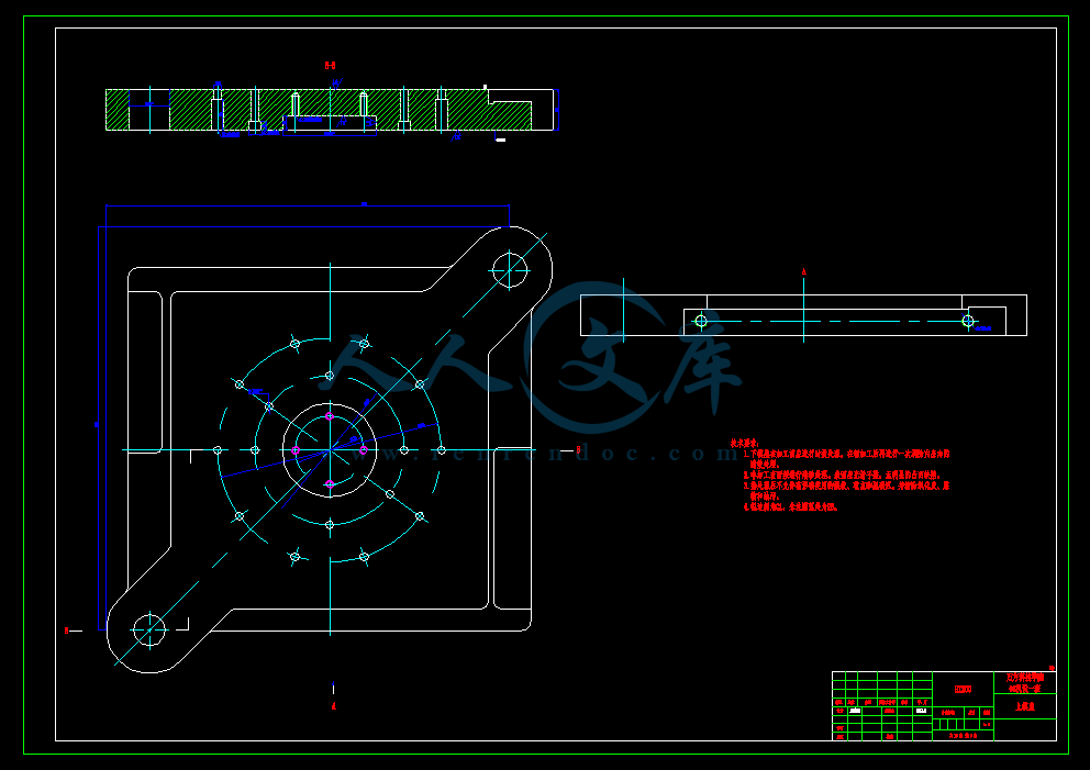
上模座A1.dwg

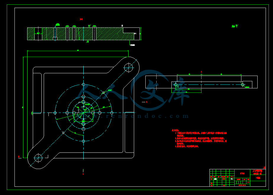
下模座A1.dwg

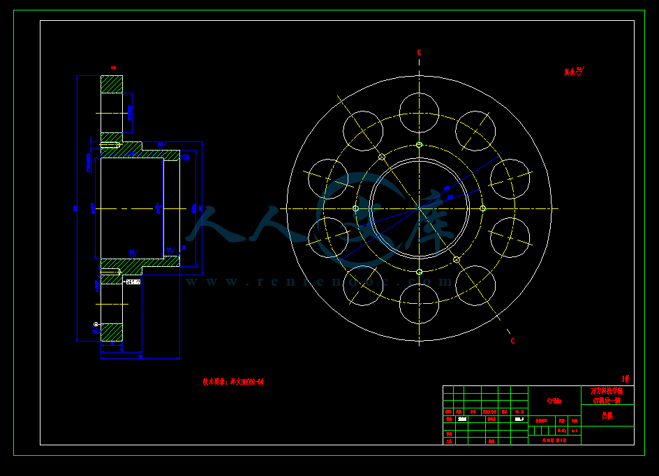
凸模1A2.dwg

凸模2A2.dwg

凸模3A4.dwg

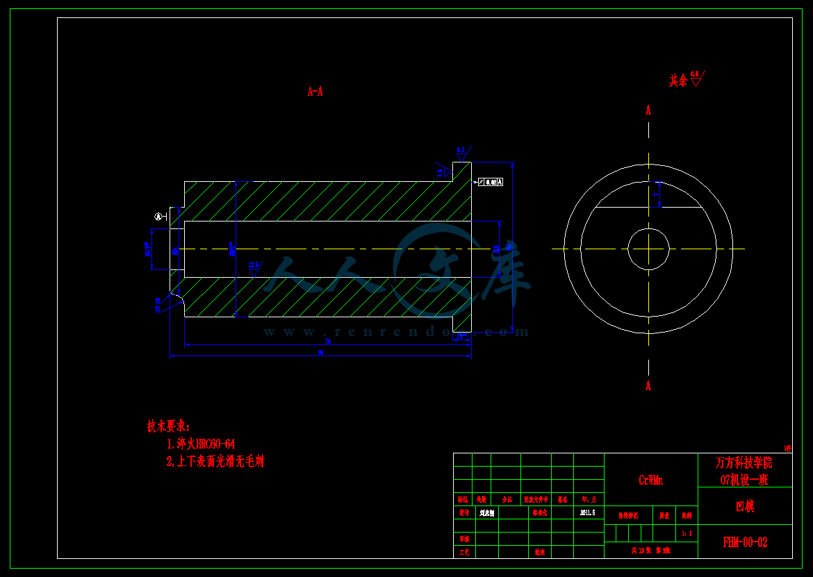
凹模1A3.dwg

凹模2A2.dwg

凹模3A3.dwg

变压器储油柜端盖.dwg

变压器储油柜端盖复合模具设计论文.doc

外文翻译--单螺杆加工机床的布局和结构.doc

端盖A3.dwg

装配图A0.dwg

摘  要

   分析了变压器储油柜端盖的结构和成形工艺,计算了毛坯尺寸和冲压力。为了提高端盖的生产效率,设计了集三工序为一体的落料拉深冲孔复合模的结构,经过工艺分析、结构设计,论证了其可能性,保证了制品的质量。

   在模具设计中,为了提高速度和效率,充分利用已经掌握的知识和资源。利用Pro/E曲面设计功能快速求出曲面的面积。利用冲模设计手册软件版快速设计冲压模具,并对模具的强度进行检验。实践证明,确实提高了设计的速度和效率。本模具设计中,由于卸料力较大,采用了组合弹簧力较大的优点解决了这一问题。在模具结构中,用顶板做凸模的定位元件,由于配合定位的距离小,容易造成凸模的折断,因而设计了凹模导向凸模,增强了凸模的强度。


关键词:落料  拉深  冲孔  复合模  模具结构

Abstract

   The structure and processing property of bellows?oil?conservator end cover for?transformers were analyzed. The blank dimensions and pressing force were calculated. The compound die of cut-tandem-punch combined with three procedures is designed in order to improve the production of end cover. The article proves its availability through technological analysis and structural design to guarantee products’ quality .

   In mold design, in order to improve pace and efficiency, fully utilize knowledge and resource that has already been grasped. Utilize Pro/E curved surface design function ask , produce area of curved surface fast , utilize the design manual software edition of the trimming die to design and press the mould fast, and the intensity to the mould is examined. Practice has proved , have really improved pace and efficiency designed. In this mold design, because of unload material to be strength relatively heavy, adopt , make up spring loud advantage solve this problem. In the mould structure, make the localization component of the protruding mould with the roof, the distance making a reservation is little because of cooperating, apt to cause protruding rupture of mould, design concave mould pour , to protruding mould , strengthen protruding intensity of mould.   

Key words: cut  tandem  punch  compound die  die structure

目  录

前  言1

1  绪  论2

1.1  我国模具市场的发展趋势3

1.2  模具技术的发展趋势5

1.2.1  模具产品发展将大型化精密化5

1.2.2  模具高速扫描及数字化系统将发挥更大的作用5

1.2.3  模具研磨抛光将向自动化、智能化方向发展6

1.2.4  模具标准件的应用将日渐广泛6

1.2.5  在模具设计制造中将全面推广CAD/CAM/CAE技术7

1.2.6  快速经济模具的前景十分广阔7

1.2.7  模具自动加工系统的研制和发展8

2  设计题目9

3  工艺分析12

3.1  经济分析12

3.1.1  冲压件成本分析12

3.1.2  降低制造成本的措施13

3.2  技术分析15

3.2.1  冲裁的结构工艺性15

3.2.2  拉深的结构工艺性16

3.3  变压器储油柜端盖的工艺分析20

3.3.1  材料20

3.3.2  零件结构20

3.3.3  尺寸精度21

4  工艺方案的制定22

4.1  工艺方案的分析22

4.1.1  修边余量22

4.1.2  计算毛坯尺寸22

4.1.3  确定是否用压边圈23

4.1.4  确定拉深次数(采用查图法)23

4.2  工艺方案的确定24

5  工艺计算26

5.1  材料排样及材料利用率的计算26

5.1.1  材料排样的选用原则26

5.1.2  确定板料规格和裁料方式27

5.2  冲压力的计算及设备的选择28

5.2.1  落料28

5.2.2  拉深29

5.2.3  起伏成形32

5.2.4  冲孔32

5.2.5  冲压设备的选择33

5.3  模具压力中心的确定36

5.4  模具刃口尺寸和公差确定36

5.4.1  坯料冲裁间隙的确定36

5.4.2  落料刃口尺寸的计算38

5.4.3  冲孔刃口尺寸的计算39

5.4.4  拉深工序工作部分的尺寸及间隙39

5.5  模具强度校核41

5.5.1  冲孔凸模的强度校核41

5.5.2  螺钉的强度校核42

6  模具主要零件结构设计44

6.1  弹性元件的设计44

6.1.1  弹簧的设计计算44

6.1.2  卸料橡胶的设计计算45

6.2  模架的选择45

6.3  工作零件的设计46

6.3.1  凹模刃口的结构型式确定46

6.3.2  凸模刃口的结构型式确定47

6.4  其它主要零件设计47

6.4.1  镶块的设计47

6.4.2  压边圈的设计48

6.4.3  卸料板的设计49

6.4.4  顶板的设计49

6.4.5  垫板的设计50

7  模具结构合理性分析52

7.1  模具结构图52

7.2  模具的工作过程53

结  论54

致  谢55

参考文献56

1.2  模具技术的发展趋势

   1.2.1  模具产品发展将大型化精密化

   模具产品成形零件的日渐大型化,以及由于高效率生产要求的一模多腔(如塑封模已达到一模几百腔)使模具日趋大型化。随着零件微型化,以及模具结构发展的要求(如多工位级进模工位数的增加,其步距精度的提高)精密模具精度已由原来的5μm提高到2~3μm,今后有些模具加工精度公差要求 在1μm以下,这就要求发展超精加工。

   1.2.2  模具高速扫描及数字化系统将发挥更大的作用

   英国雷尼绍公司的模具扫描系统,已在我国200多家模具厂点得到应用,取得良好效果。该系统提供了从模型或实物扫描到加工出期望的的模型所需的诸多功能,大大缩短的研制制造周期。如RENSCAN200快速扫描系统,可快速安装在已有的数控铣床及加工中心上, 用雷尼绍的SP2-1扫描测头实现快速数据采集,控制核心是雷尼绍TRACECUT软件,可自动生成各种不同数控系统的加工等程序及不同格式的CAD数据。用于模具制造业的“逆向工程”。该公司又推出了CYCLON高速扫描机,这是一台独立工作的专门用来扫描的设备,不占用加工机床的工作时间。其扫描速度最高可达3m/min,大大缩短了模具制造周期,另外,其数据采集速度比RENSCAN200快,定时探针接触力小,因此可以用非常细的探针,用来扫描细小的模具和细微的特征表面 ,扩大模具生产的品种范围。由于模具扫描系统已在汽车、摩托车、定电等行业得到成功应用,相信在“十五”期间将发挥更大作用。

   1.2.3  模具研磨抛光将向自动化、智能化方向发展

   模具表面的精加工是模具加工中未能很好解决的难题之一。模具表面的质量对模具使用寿命、制件外观质量等方面均有较大的影响,我国目前仍以手工研磨抛光为主,不仅效率低(约占整个模具制造周期的1/3),且工人劳动强度大,质量不稳定,制约了我国模具加工 向更高层次发展。因此,研究抛光的自动化、智能化是重要的发展趋势。日本已研制了数控 研磨机,可实现三维曲面模具研磨抛光的自动化、智能化是重要的发展趋势。日本已研制了 数控研磨机,可实现三给曲面模具研磨抛光的自动化。另外,由于模具型腔形状复杂,任何 一种研磨抛光方法都有一定局限性。应注意发展特种研磨与抛光、如挤压衍磨、电化学抛光、超声抛光以及复合抛光工艺与装备,以提高模具表面质量。

   1.2.4  模具标准件的应用将日渐广泛

   使用模具标准件不但能缩短模具制造周期,而且能提高模具质量和降低模具制造成本。因此,模具标准件的应用必将日渐广泛。为此,首先要制订统一的国家标准,并严格按标准生产;其次要逐步形成规模生产,提高标准件质量、降低成本;再次是要进一步增加标准件规格品种,发展和完善联销网,保证供货迅速。

   1.2.5  在模具设计制造中将全面推广CAD/CAM/CAE技术

   模具CAD/CAM/CAE技术是模具技术发展的一个重要里程碑。实践证明,模具CAD/CAM/CAE 技术是模具设计制造的发展方向。现在,全面普及CAD/CAM/CAE技术已基本成熟。由于模具 CAD/CAM技术已发展成为一项比较成熟的共性技术,近年来模具CAD/CAM技术的硬件与软件价格已降低到中小企业普遍可以接受的程度,特别是微机的普及应用,更为广大模具企业普及模具CAD/CAM技术创造了良好的条件。随着微机软件的发展和进步,技术培训工作也日趋简化。在普及推广模具CAD/CAM技术的过程中,应抓住机遇,重点扶持国产模具软件的开发 和应用。

   加大技术培训和技术服务的力度。应进一步扩大CAE技术的应用范围。对于已普及了模具CAD/CAM技术的一批以家电行业代表的企业来说,应积极做好模具CAD/CAM技术的深化应用工作,即开展企业信息化工程,可从CAPP,PDM, CIMS,VR逐步深化和提高。

   1.2.6  快速经济模具的前景十分广阔

   现在是多品种、少批量生产的时代,到下一个世纪,这种生产方式占工业生产的比例将达75%以上。一方面是制品使用周期短,品种更新快,另一方面制品的花样变化频繁,均 要求模具的生产周期越快越好。因此,开发快速经济具越来越引起人们的重视。例如,研制 各种超塑性材料(环氧、聚脂等)制作或其中填充金属粉末、玻璃纤维等的简易模具;中、低 熔点合金模具、喷涂成型模具、快速电铸模、陶瓷型精铸模、陶瓷型吸塑模、叠层模及快速 原型制造模具等快速经济模具将进一步发展。快换模架、快换冲头等也将日益发展。另外, 采用计算机控制和机械手操作的快速换模装置、快速试模技术也会得到发展和提高。

   1.2.7  模具自动加工系统的研制和发展

   随着各种新技术的迅速发展,国外已出现了模具自动加工系统。这也是我国长远发展的目标。模具自动加工系统应有如下特征:多台机床合理组合;配有随行定位夹具或定位盘;有完整的机具、刀具数控库;有完整的数控柔性同步系统;有质量监测控制系统。   变压器除应用于电力系统外,还应用于一些工业部门中,如:在电炉整流、电焊设备中、在船舶、电机等设备中都应用特种变压器,此外,在高压试验,测量设备和控制设备中也应用着各式的变压器。

   储油柜是油浸式变压器重要的保护性器件,是用于满足绝缘油因温度变化而产生体积变化(热胀冷缩)所必需的补偿容器。对于35KV以上油浸式变压器要求储油柜做到全密封(一般通过全焊接固定),即绝缘油与大气隔离,防止空气中的水和氧使绝缘油受潮和老化,影响绝缘性能。

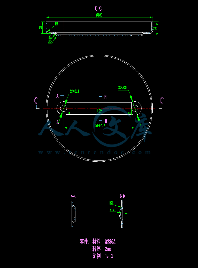
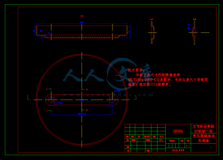
   该端盖是变压器储油柜上的一个零件,里面安装有油量管,安装在储油柜的上端。变压器储油柜端盖是一种工业用品,市场需求量较大,所以这种端盖的生产批量较大,其产品图二维CAD图如图2-2:

    材料Q235,厚度t=2mm。3  工艺分析

   工件的工艺性是指工件对冲压加工工艺的适应性,它是从冲压加工角度对产品设计提出的工艺要求。工艺分析就是要判断产品在技术上能否保质,保量地稳定生产,在经济上是否有效益。因此,冲压工艺就是对产品的冲压工艺方案进行技术和经济的可行性分析。良好的工艺性体现在材料消耗少,工序数目少,模具结构简单而寿命长,产品质量稳定,操作简单方便。

3.1  经济分析

   所谓经济性,就是以最小的耗费取得最大的经济效果。也就是生产中的“最小最大”原则。在冲压生产中,保证产品质量,完成产品数量、品种计划的前提下,产品成本越低,说明企业经济效果越大。

   3.1.1  冲压件成本分析

   产品成本受产量的影响较大,特别是冲压生产尤为突出。在一定条件下,企业生产产品数量的增减,将会引起成本中某些费用的变化,其结果使得成本发生波动。为此可将产品成本分为固定费用和变动费用两部分。固定费用是指在一定时期和一定产量范围内,它的总额不随产量变动而变动,它是维持生产能力而基本不变的费用。例如模具、设备折旧费,加工费中的固定工资部分和各种经费等。但是单位固定费用,也就是分摊在每个产品上的固定费用却是可变的。即单位固定费用与产量成反比例变化。

   变动费用是指它的总额随产量的增减而成比例增减。例如产品直接耗用的原材料费、外购件费、外协件加工费等等。但就产品单位费用而言,变动费用则基本不变。

   上述可知,冲压件生产成本是由固定费和可变费这两部分组成的,所以只要设法降低固定费用或可变费用,都能使生产成本降低,利润增加。可见企业要提高经济效益,就要在降低成本上下功夫。

   3.1.2  降低制造成本的措施

   降低产品成本,包括增产、节约两个方面。增产可降低产品成本中的固定费用,相对地减少消耗,节约便能直接降低消耗,它们都是降低成本的重要途径。冲压件的成本包括材料费、加工费、模具费等项。因此,降低成本,就是要降低以上各项费用。以下讨论降低成本的措施。

   3.1.2.1  工艺合理化

   冲压生产中,工艺合理化是降低成本的有力手段,一般在制定新产品工艺时进行。当产量发生变化,模具寿命短或因事故发生损坏时,由于更改产品设计而改变模具时,以及变更设备等生产条件发生变化时,要重新讨论(研究)产品工艺。由于工艺的合理化能降低模具费、节约加工工时降低材料费等,所以必然降低零件总成本。

   在制定工艺时,工序的分散与集中是比较复杂的问题。它取决于零件的批量、结构(形状)、质量要求、工艺特点等。对于板材冲压件,一般说来,在大批量生产情况下,应当尽量把工序集中起来,采用复合或连续模进行冲压,很小的零件,适合于复合或连续冲压加工,这样既提高了生产率,又能安全生产。复合模对于大的零件也是适合的,因为一副大的复合模,有时比两副同样大小的单工序模的费用低,而小批量生产时,则以采用单工序模分散冲压为宜。

   根据实践经验,集中到一副模具上的工序数量不宜太多,对于复合模,一般为2~3个工序,最多4个工序,对于连续模,集中的工序数可以多些。

3.1.2.2  多个工件同时成形

   产量较大时,采用多件同时冲压,可使模具费、材料费和加工费降低,同时有利于成形表面拉力均匀化。左右对称成形时,不仅可使变形均匀,改善受力状况,同时还降低了成本。

   3.1.2.3  冲压过程的自动化及高速化

   自动化生产,从安全和降低成本两个方面来看,将成为冲压加工的发展方向。今后不仅大批量生产中采用自动化,在小批量生产中也可采用自动化生产。在大批量生产中采用自动化时,虽然模具费用较高,但生产率高,产量大,分摊到每个工件上的模具折旧费和加工费却比单件小批生产时要低

   从生产安全性考虑,在小批量多品种生产中采用自动化也是可取的,但自动化的经济性问题,急待研究。在自动化生产中,降低成本的手段是高速化。与高速化并行的是多列化,这样可以降低加工费用和提高材料利用率。

   为实现压力机的高速化,需要相应解决噪音振动和延长模具寿命问题。高速压力机要求足够的刚度和精度,一般以闭式双点结构为宜,为减少噪音和振动,倾向于铸铁机身,而且运动部件要求实现动平衡。为延长模具寿命,可采用高寿命的新材料,如硬质合金模具和模具表面强化处理。

   3.1.2.4  提高材料利用率,降低材料费

   在冲压生产中,工件的原材料费占制造成本的60%,左右,所以节约原材料,利用废料具有非常重要的意义。提高材料利用率是降低冲压件制造成本的重要措施之一。特别是材料单价高的工件,必须慎重研究。降低材料费的方法如下:

  (1)在满足零件强度和使用要求的情况下,减少材料厚度。

  (2)降低材料单价。

  (3)改进毛坯形状,合理排样。

  (4)减少搭边,采用少废料或无废料排样。

  (5)对称压制。

  (6)组合排样。

   参考文献

[1]党根茂,骆志斌,李集仁.模具设计与制造[M].西安电子科技大学出版社,2001

[2]中国机械工业教育协会.冷冲模设计及制造[M].机械工业出版社,2005

[3]彭建声.冷冲压技术问答[M].机械工业出版社,1984

[4]彭建声,王新华,张敬国.冷冲模制造与修理[M].机械工业出版,1985

[5]梁炳文,胡世光.板料成型塑性理论[M].机械工业出版社,1987

[6]姜军辉.汽车车架横梁冲压工艺设计[J].汽车研究与开发,1995

[7]翟德梅.提高电机冲片冷冲模寿命的措施[J].电加工与模具,2001

[8]周科年.汽车纵梁冲孔落料复合模[J].模具工业,1999

[9]肖景容.冲压工艺学[M].机械工业出版社,1999

[10]钟翔山.轴壳扩径、缩口复合模设计[J].模具技术,2006

[11]杨宝顺.锅盖落料拉深冲孔切边复合模设计[J].模具技术,2006

[12]翟德梅,李铁明.机架复合冲裁模具的研制[J].电加工与具,2004

[13]模具实用技术丛书编委会.冲模设计应用实例[M].机械工业出版社,2004,4

[14]姜奎华.冲压工艺与模具技术[M].机械工业出版社,2005,8

[15]郑家贤.冲压工艺与模具设计实用技术[M].机械工业出版社,2005,8

内容简介:
河南理工大学万方科技学院本科毕业论文附录: 外文资料与中文翻译外文资料:Concerning single-screw machine layout and structure Decide the size of the compressor displacement of the stars round, screw diameter, mesh size and the size of the center distance, so different in diameter screw, machine tool spindle and the rotary center are also different. To meet the processing of different diameter screw, single screw Currently the layout of machine tools in general there are several options. The first is: machine tool rotary tool spindle center and the center distance for the fixed Machine tool rotary tool spindle center and the center distance for the fixed, can not adjust the center distance. Processing of several of the screw diameter on the center distance required several different specifications of the machine. Advantages: simple structure of the machine. Disadvantage: each machine can only process a specification of the screw, when the market on a certain specification requirements when the screw compressor, resulting in a machine, other machine idle. The second: the machine tool spindle box for rotary Processing screw machine according to the size of the diameter at the processing before a point of rotating spindle box. Spindle box that the machine can turn on a machine at the above-mentioned article on the use of the improvements, with the first structure of a machine tool is basically the same. Advantages: the structure of machine tool easy to adapt to a variety of specifications of the processing screw. One disadvantage: after the rotating spindle box and the tool spindle turning center line distance between the center line of accurate measurement difficult. 2 disadvantage: after the rotating spindle spindle box and the front surface of the rotary cutter centerline distance between the reduction of the larger diameter of the screw processing is limited. The third: the machine tool spindle box for horizontal mobile Box at the bottom of the spindle and the base there is arranged between the rectangular sliding rail, spindle box perpendicular to the direction of movement of spindle centerline and perpendicular to the centerline of the tool rotation. Through the power of the spindle box spline shaft to the base of the tool feed mechanism. Screw diameter, according to the size of the processing in the processing of the previous round by hand to the body put into the screw spindle box moved to the appropriate location, and then screw the spindle box on a fixed base. Spindle box available from the mobile Grating detection, position error 0.005mm. Horizontal spindle box can be used as a mobile machine can process diameter 95 385mm any kind between the screw specifications. 95 385mm processing because of the diameter of the screw, causing the front surface and the tool spindle rotation the distance between the center line of the margin is too large, the actual application in the design specifications of the machine into two, a 95 205mm machine screw diameter Another 180 385mm machine screw diameter. Advantages: a variety of tools to adapt to the specifications of the processing screw, each screw specifications need not be provided with the appropriate machine tools. Disadvantage: the structure of machine tools and machine tool assembly of the two kinds of more complex machine tools, machine tools than the cost of two kinds of machine tools before the high. Second, introduce the structure of machine tool spindle The level of machine tool spindle box on the main axis and the base of the vertical axis determines the degree of precision was the precision screw machining, at the same time screw compressor at a speed of thousands of high-speed rotary switch, the accuracy of the screw will be less so that the compressor have a fever, vibration, low efficiency, such as wear and tear situation quickly. Currently available single-screw machine spindle structure of the program has the following two. The first is: bearing radial clearance is not adjustable spindle structure Before spindle bearing out the use of one pairs of cylindrical roller bearings and thrust ball bearing combination of both, the main use of double row cylindrical roller bearings under radial cutting force, the use of two ball bearings to bear axial thrust cutting force. After the general adoption of the spindle bearings out one pairs of cylindrical roller bearings or a ball bearing to the heart. Main advantages of this structure: the main axis of the processing and assembly of simple, low cost. One disadvantage: because the main axis of the radial bearing clearance can not be adjusted so poor precision spindle. Although the use of bearings and shaft diameter fit to eliminate the radial bearing clearance, but each bearing diameter and radial clearance is not a fixed value, so it is difficult to design and processing to the quasi-axial-radial and bearings with bore tolerances. 2 disadvantage: it is very difficult to buy in the market of domestically produced or imported, C, D or P4, P5 class thrust ball bearings, machine tool manufacturing plant commonly used alternative to the use of ordinary class bearings, which also affected the accuracy of the enhance spindle. Bearing radial clearance adjustable spindle structure do not apply to the general accuracy of the general machine tools, does not apply to require a higher accuracy of the spindle of machine tools. The second: the radial bearing clearance adjustable spindle structure Before the adoption of a spindle bearing P4 class of double row tapered hole cylindrical roller bearings and a P4-class double row ball bearing thrust to the combination of heart. The use of the spindle hole of the double row tapered cylindrical roller bearings under radial cutting force, the use of double row ball bearing thrust to the heart to bear part of the axial and radial cutting force cutting force. Spindle bearings generally used after a P5 class of double row tapered hole cylindrical roller bearings. Double row tapered hole cylindrical roller bearings with inner ring and shaft are tapered 1:12, bearing lock nut with a round led a bearing in the axial displacement of the inner ring bearings and expansion, to reduce or eliminate Bearing radial clearance purposes. Main structure of such advantages: high precision spindle. At the front spindle diameter 230mm noodle on the end measuring spindle Beat value of 0.010mm. 230mm cylindrical spindle at the front end on the radial axis measurement value of Beat 0.005mm. The second structure of the spindle of a precision spindle accuracy than the first about 50% improve. Main disadvantage of this structure: The principal axis of the more complicated process, the spindle assembly also has the experience necessary to make the workers to operate the spindle achieve the desired numerical accuracy. Third, the depth of the tool feed control Required different processing screw diameter spiral groove depth is also different from the depth of the spiral groove mm from dozens to more than 100 millimeters range around the tool into the institutions required to feed the thousands of ring rotation in order to achieve a screw machining . Feed because of the tool in the tool rotating at the same time achieve motion feed, so on a number of general machine tools used in mechanical, electrical control method of depth of cut does not apply to single-screw machine. Single screw machine tools give agencies into the following different methods can be feed to control the depth of purpose. The first is: friction clutch and electrical switches to control the depth of the tool feed Its principle is to control depth of cut increases the tool cutter feed mechanism increases the load torque so that the tool feeding mechanism of the friction transmission chain slipping clutch, a mechanical linkage concurrent silent trigger electrical switches, optical signal prompted operator, when manual operator to disconnect the tool into the power sector. The advantages of this control method are: the control method is simple and spare parts processing and operational power from the impact of a sudden. Disadvantage are: processing of different diameter screw to adjust the clutch friction discs pressed the preload spring. Material because of the density of each screw, and the hardness of the existence of subtle differences in the degree of cutting tools sharp differences exist, thus the accuracy of this control method was not too accurate, may lead to screw spiral groove depth tolerance is too large. The second: use of an electromagnetic clutch, encoder control tool into the mix to the depth of Tool feed system, equipped with electromagnetic clutch and a tool for detecting the number of rotating ring gear and a gun encoder. It is a tool of control principle hand screw surface encoder to start counting switch, then start counting counting device, when the rotary tool to pre-set number of laps when the cutting depth is reached, the electromagnetic clutch automatic off open to the power tool into the concurrent silent, optical signal parts prompted the operator has finished processing. The detection device through the digital display shows the number of feed circles or feed. Torn off and the electromagnetic clutch, the tool does not only into the rotation with the vertical shaft to the sport. The advantages of this control method are: the depth of the spiral groove screw tolerance control more accurate, because of several significant table shows the depth of processing, or want a few laps and the depth of processing or circle the number of operations is also very intuitive and user-friendly. Disadvantage are: electrical control of machine tools at the same time more complex parts of this control method at the processing plant, if a sudden power failure, the prior data set will be lost. If you add in the electrical control of the battery to power at the early-dimensional detection devices to maintain the job, the problem can be resolved. Four, the control gear drive space Single screw machine screw in the processing, due to the spiral groove in the rotary tool and the workpiece rotation to complete the synthesis process. Just cut into the workpiece when the tool in the tangential direction of rotation has been going on a greater resistance knife, cutting tool at the workpiece to be cut when the role of the spiral groove, the tool in the tangential direction of rotation has been going up against a smaller knife and even by the spiral groove thrust workpiece. Because there is a box-hole processing machine tool, gear and other processing error, the tool axis of rotation of the drive space is too large, large amount of so-called open. Detect drive way too much space is a fixed power input shaft and output shaft rotation shaking, in the case of the transmission structure of conventional design and manufacture of machine tools, the transmission output shaft angle space at more than ten degrees to the dozens of degrees. Transmission gap caused by too large spiral screw groove surface then there is obvious marks, thus affecting the machining accuracy of the screw. Upon completion of the assembly machine tool axis of rotation of the drive space is too large, in fact are subject to various errors gear, creating a backlash of the gear is too large. Machine tools in the mechanical transmission gear are used regardless of the accuracy of a few of the class, the designers take into account the gear manufacturing error, processing error box center distance, temperature, lubricating oil film thickness, the assembly error and other factors, machine design must ensure that transmission gear A certain amount of backlash, backlash decide the size of the gear tooth thickness tolerance size. Single-screw machine has the Main Drive from other machine tool structure specificity. In order to reduce transmission or reasonable gap single-screw machine tools currently used by the following two ways. The first is: the installation at the output shaft brake Tool at the output shaft rotating the location of cylindrical symmetry with radial brake, brake stand up to the tool front-end of the cylindrical rotary output shaft, brake for spring preload. The working principle of the brake is generated by the friction brake to increase the output shaft damping, reducing the sensitivity of the rotation axis. Are: brake and easy does not change the structure of the original machine tool structure, the method of indirect reduction to achieve the purpose of drive space, in practical applications there is a certain effect. One disadvantage: the pre-spring brake tool because of the cylindrical output shaft to exert a greater radial force, in fact increases the load machine torque, resulting in increased motor power at the same time gears, bearings to accelerate wear and tear. Disadvantage 2: pre-spring brake because of the output shaft of the cylindrical tool to exert a greater radial force on the possible geometry of the tool output shaft a negative impact on accuracy. Conclusion: This article describes four areas from existing single-screw machine layout and structure, and put out the advantages and disadvantages of the list, because of the compressor plant single-screw machine tools and machine tool external Security information, the above introduction there is inevitably one-sided and wrong, and are therefore single-screw compressor for the production of reference works. 中文翻译: 单螺杆加工机床的布局和结构一、介绍机床的布局 压缩机排气量的大小决定了星轮、螺杆直径的大小和啮合中心距的大小,因此螺杆直径的不同,机床的主轴与刀具的回转中心也不同。为满足加工不同直径的螺杆,目前国内单螺杆加工机床的布局大致有以下几种方案。 第一种:机床的主轴与刀具回转中心的中心距为固定式 机床的主轴与刀具回转中心的中心距为固定式,中心距不可调整。加工几种直径的螺杆就需要几种中心距规格不同的机床。 优点:机床的结构简单。 缺点:每种机床只能加工一种规格的螺杆,当市场上某种规格的压缩机螺杆需要量大时,造成一台机床加工,其他机床闲置。 第二种:机床的主轴箱为可回转式 机床可根据加工螺杆直径的大小在加工前把主轴箱旋转一个角度。这种主轴箱能够回转的机床是对上述第一种机床在使用方法上的改进,与第一种机床的结构基本相同。 优点:机床的结构简单,能适应多种规格螺杆的加工。 缺点1:主轴箱旋转后主轴回转中心线与刀具回转中心线间的距离不易精确测量。 缺点2:主轴箱旋转后主轴前端面与刀具的回转中心线间的距离减少,因此加工较大直径的螺杆受到限制。 第三种:机床的主轴箱为横向移动式 主轴箱底部与底座之间布置有矩形滑动导轨,主轴箱移动的方向垂直于主轴回转中心线并垂直于刀具回转中心线。主轴箱的动力通过花键轴传给底座内的刀具进给机构。 根据加工螺杆直径的大小,在加工前用手轮丝杠进给机构把主轴箱移动到适当位置,然后用螺钉将主轴箱固定在底座上。主轴箱的移动距离可用光栅尺检测,位置误差0.005mm。 采用主轴箱可横向移动的一个机床就可以加工直径95385mm之间任何一种规格的螺杆。 由于加工95385mm直径的螺杆,造成主轴前端面与刀具回转中心线间的距离差值过大,因此在实际应用时设计成两种规格的机床,一个机床加工95205mm直径的螺杆,另一个机床加工18038
温馨提示:
1: 本站所有资源如无特殊说明,都需要本地电脑安装OFFICE2007和PDF阅读器。图纸软件为CAD,CAXA,PROE,UG,SolidWorks等.压缩文件请下载最新的WinRAR软件解压。
2: 本站的文档不包含任何第三方提供的附件图纸等,如果需要附件,请联系上传者。文件的所有权益归上传用户所有。
3.本站RAR压缩包中若带图纸,网页内容里面会有图纸预览,若没有图纸预览就没有图纸。
4. 未经权益所有人同意不得将文件中的内容挪作商业或盈利用途。
5. 人人文库网仅提供信息存储空间,仅对用户上传内容的表现方式做保护处理,对用户上传分享的文档内容本身不做任何修改或编辑,并不能对任何下载内容负责。
6. 下载文件中如有侵权或不适当内容,请与我们联系,我们立即纠正。
7. 本站不保证下载资源的准确性、安全性和完整性, 同时也不承担用户因使用这些下载资源对自己和他人造成任何形式的伤害或损失。
提示  人人文库网所有资源均是用户自行上传分享,仅供网友学习交流,未经上传用户书面授权,请勿作他用。
关于本文
本文标题:变压器储油柜端盖复合模具设计【11张CAD图纸】【优秀】
链接地址:https://www.renrendoc.com/p-291834.html

官方联系方式

2:不支持迅雷下载,请使用浏览器下载   
3:不支持QQ浏览器下载,请用其他浏览器   
4:下载后的文档和图纸-无水印   
5:文档经过压缩,下载后原文更清晰   
关于我们 - 网站声明 - 网站地图 - 资源地图 - 友情链接 - 网站客服 - 联系我们

网站客服QQ:2881952447     

copyright@ 2020-2025  renrendoc.com 人人文库版权所有   联系电话:400-852-1180

备案号:蜀ICP备2022000484号-2       经营许可证: 川B2-20220663       公网安备川公网安备: 51019002004831号

本站为文档C2C交易模式,即用户上传的文档直接被用户下载,本站只是中间服务平台,本站所有文档下载所得的收益归上传人(含作者)所有。人人文库网仅提供信息存储空间,仅对用户上传内容的表现方式做保护处理,对上载内容本身不做任何修改或编辑。若文档所含内容侵犯了您的版权或隐私,请立即通知人人文库网,我们立即给予删除!