超声珩磨机床的设计论文.doc

超声珩磨机床的设计【8张CAD图纸】【优秀】

收藏

压缩包内文档预览:(预览前20页/共58页)
预览图 预览图 预览图 预览图 预览图 预览图 预览图 预览图 预览图 预览图 预览图 预览图 预览图 预览图 预览图 预览图 预览图 预览图 预览图 预览图
编号:291922    类型:共享资源    大小:3.03MB    格式:RAR    上传时间:2014-06-13 上传人:上*** IP属地:江苏
50
积分
关 键 词:
超声 珩磨机床 设计 cad图纸
资源描述:

超声珩磨机床的设计

57页 21000字数+说明书+外文翻译+开题报告+8张CAD图纸

中期报告.doc

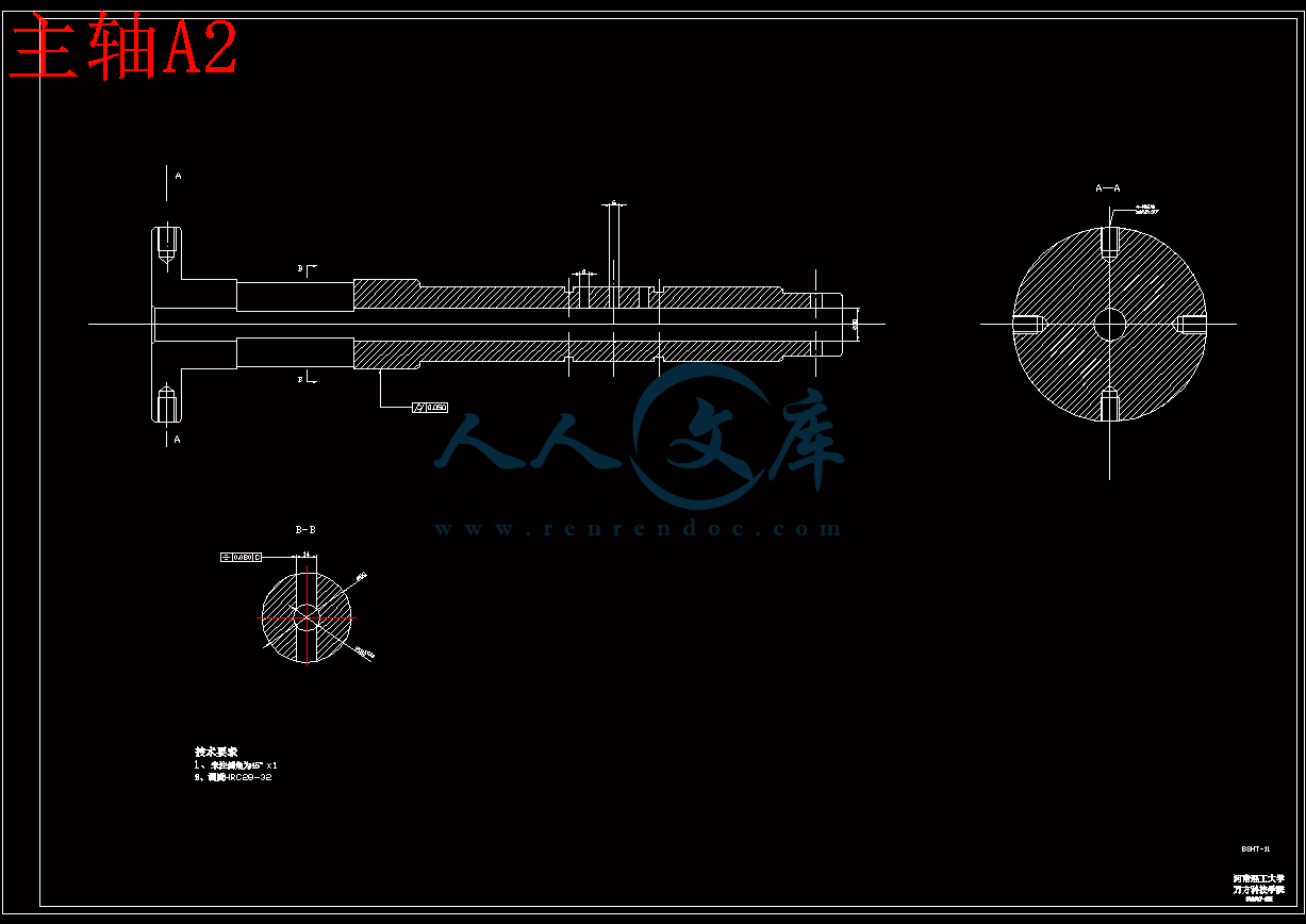
主轴A2.dwg

外文翻译--一种研究光学玻璃机械加工的实验.doc

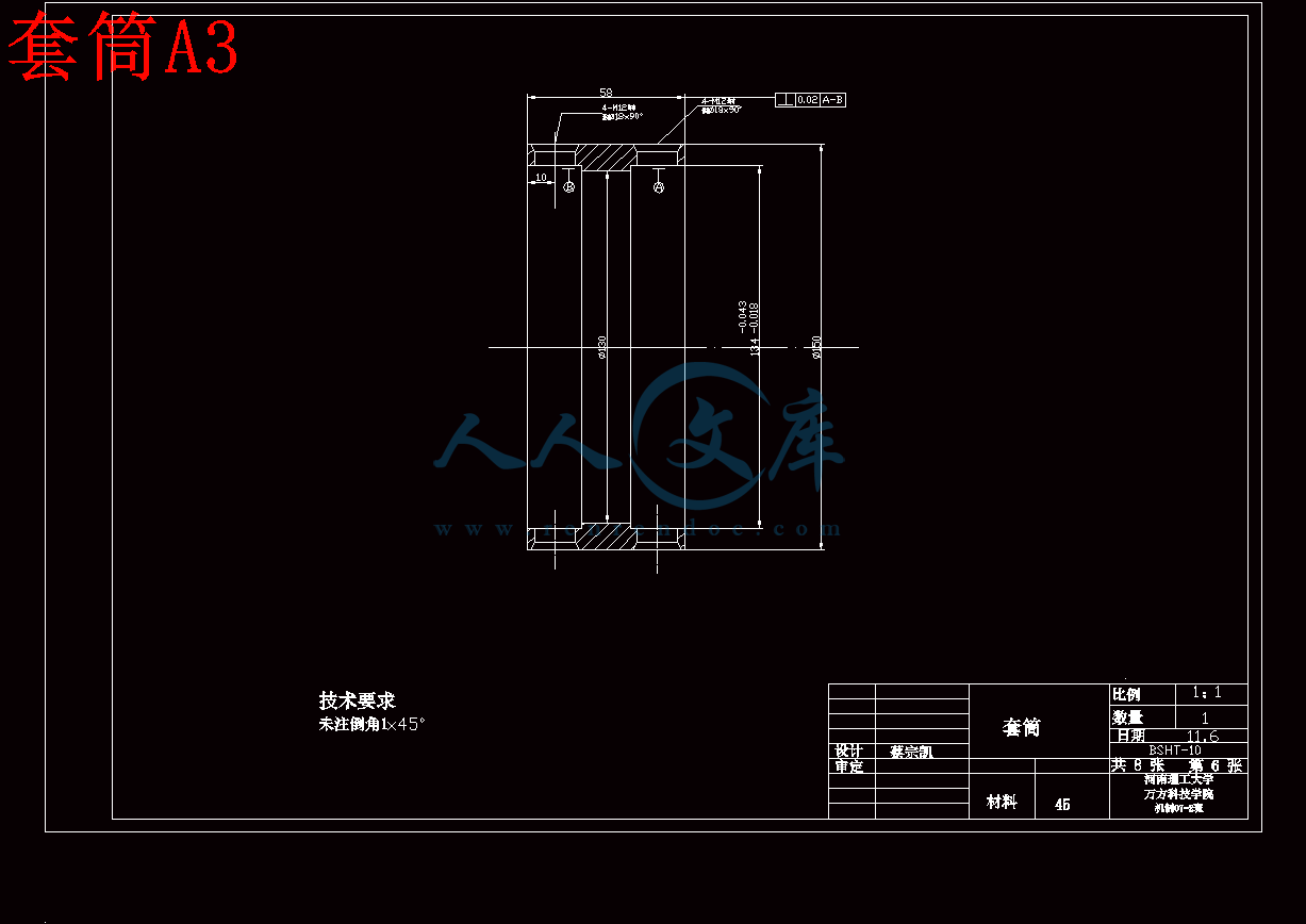
套筒A3.dwg

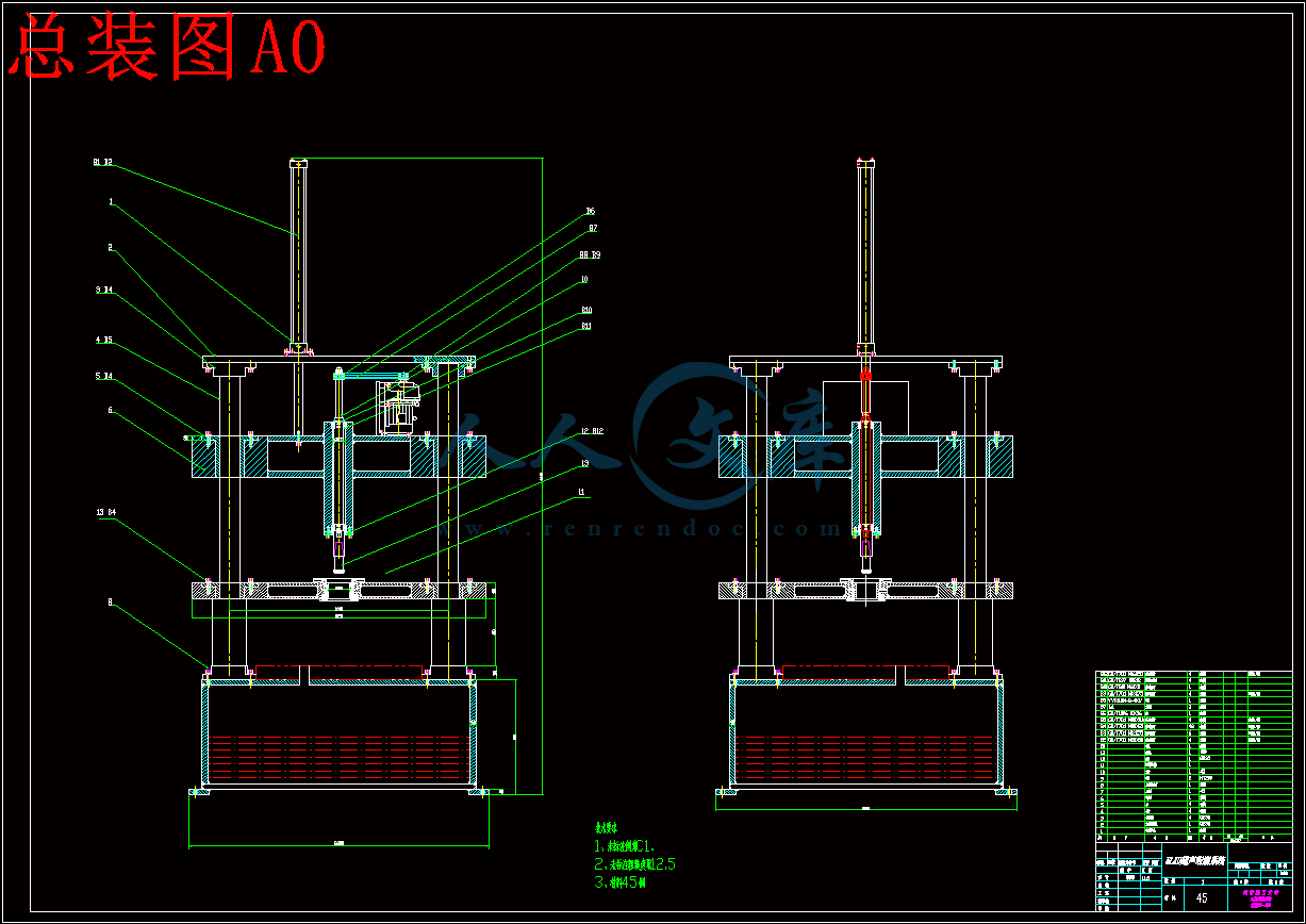
总装图A0.dwg

油石A3.dwg

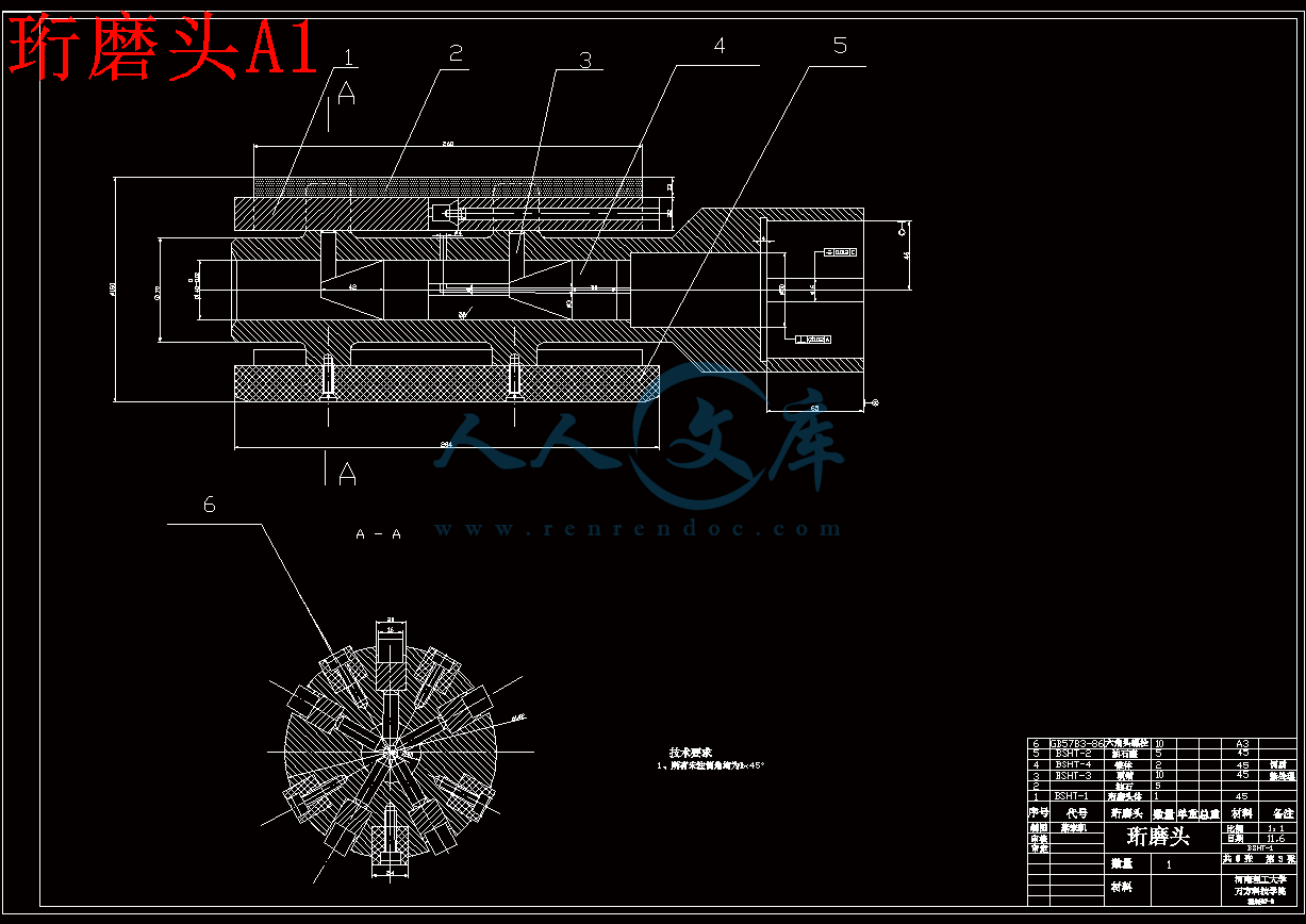
珩磨头A1.dwg

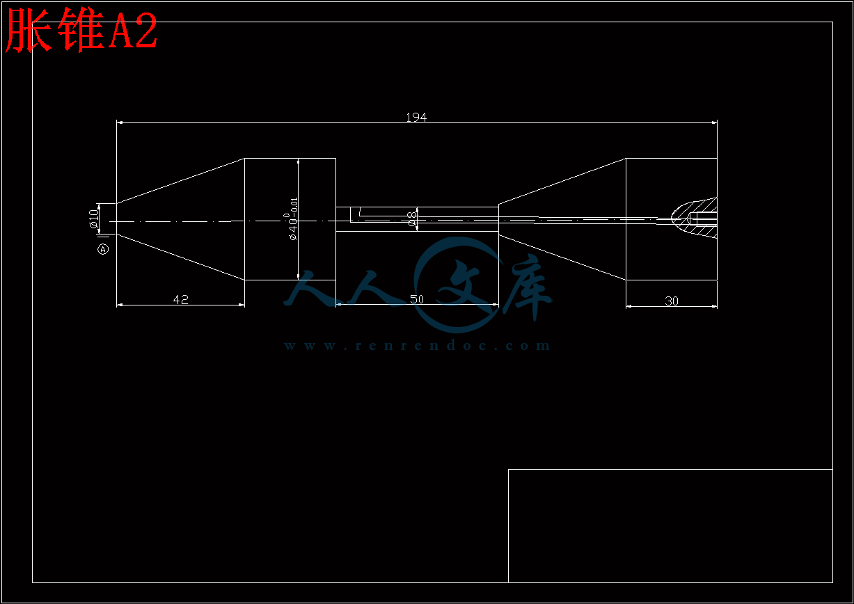
胀锥A2.dwg

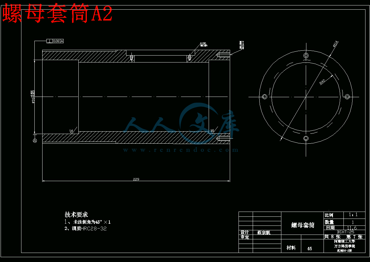
螺母套筒A2.dwg

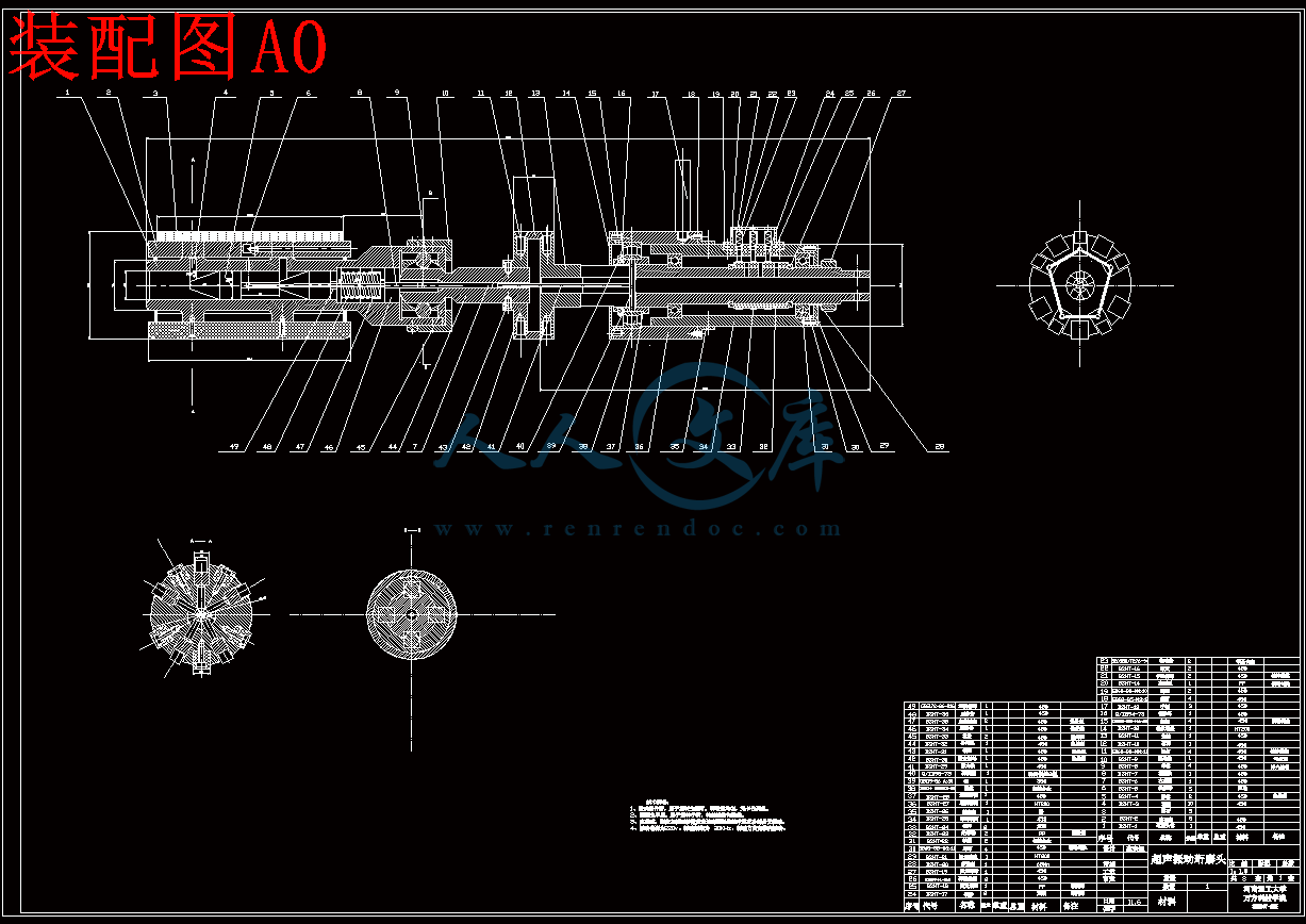
装配图A0.dwg

超声珩磨机床的设计开题报告.doc

超声珩磨机床的设计论文.doc

摘 要

   超声加工广泛应用于磨削加工,已经成为新一代精密加工发展方向之一。本文主要是从珩磨应用这一角度来作一个具体介绍。

    从介绍超声加工原理和特点与珩磨的特点、原理以及应用入手,本设计引出超声珩磨加工,介绍其原理应用并详细阐述超声波振动珩磨头的基本结构及设计要点。在以上基础上,针对设计目标分别对超声波振动珩磨的各个组件进行结构和理论设计与分析并校核。珩磨是一种固结磨粒压力进给切削的精整加工方法,不仅能切除较大的加工余量而且能有效的提高工件的尺寸精度和形状精度、降低工件表面的粗糙度。珩磨主要加工内孔,在一定条件下也可以加工外圆、平面、球面、齿面。珩磨轨迹是交叉网纹,珩磨加工变质层很小能提高工件的使用寿命,因为珩磨油石磨粒受两个方向的磨削阻力所以它有自锐作用。珩磨与主轴一般采用浮动连接,符合光整加工的的浮动加工原理。为了改善珩磨加工的使用性能可采用分粗、精珩磨的平顶珩磨。目前珩磨正向改善珩磨油石组合安装的方向发展,以便实现一次加工就能实现粗珩和精珩两到工序。

关键词:超声加工  珩磨  浮动连接

Abstract

   Ultrasonic processing is widely applied in the process of rubing, already becoming  a new generation of developing direction of accuratelly processing. This study  mainly uses this angle about how to  practice  honing operation to make a concrete introduction.

   From introducing  the characteristics and principle of ultrasonic processing and the  use of honing, it is drawing  ultrasonic honing processing , recommending its  principle use and explaining ultrasonic vibration basic structure of the head of honing and the main point in detail. On the basis of the summary above , this  study will give a  design of     structural and theoretical of each package of ultrasonic vibration honing separately to the designed object,and of course  analyse and check it. It is a kind of solid knot that honing whet is to process the method when a pressure enter to slice, not only can it cut off bigger process but the amount of remaining and size accuracy and shape accuracy of the ability  valid exaltation  work piece, lower rough degree of a surface of work.The honing whets to mainly process inside the bore, can also process the outside circle, flat surface, surface of sphere under the condition of certain.The honing whet is to cross the net surface, the  honing  whets is to process to change the layer very small and it can raise the service life of the work piece, because the honing whets of the oil stone is to pare the resistance so it has the function of cutting .The honing whets is to adopt the conjunction with principal axis generally, matching the light  processed float.Whet to process ,for the sake of the improvement of the function , can adopt the an accurate honing.Currently the honing whet just the direction development that whet the oil stone combination to press to pack toward the improvement honing , in order to carry out to process once and then can carry out the thick honing and the accurate honing to arrive the work preface.

Keyword:  Processing ultrasonically   Honing    Floating connector

目 录

前 言1

1 绪论3

1.1珩磨加工特点及应用范围3

1.1.1珩磨加工3

1.1.2珩磨加工特点4

1.1.3珩磨工艺应用范围5

1.2珩磨加工的工作原理5

1.2.1珩磨加工的原理5

1.2.2珩磨运动过程6

1.2.3珩磨的切削过程7

2珩磨头的设计10

2.1珩磨头设计因素及要求10

2.1.1珩磨头设计时应考虑的因素10

2.1.2对珩磨头结构的基本要求10

2.2珩磨头的结构形式12

2.2.1通用珩磨头14

2.2.2小孔珩磨头15

2.2.3大孔珩磨头20

2.2.4平项珩磨头20

2.2.5特殊珩磨头21

2.3珩磨油石23

2.3.1珩磨油石的性能24

2.3.2珩磨油石的规格及数量28

2.3.3珩磨油石的连接方式30

2.4常见的珩磨缺陷和解决措施31

2.4.1圆度误差超差31

2.4.2孔的直线度误差超差31

2.4.3孔的尺寸超差32

2.4.4珩磨表面粗糙度达不到工艺要求32

2.4.5珩磨表面刮伤32

3超声珩磨34

3.1 珩磨加工34

3.1.1  珩磨加工特点34

3.1.2珩磨工艺应用范围34

3.2  超声珩磨工作原理及加工特点35

3.2.1 超声珩磨工作原理35

3.2.2超声珩磨加工特点37

3.3换能器的选用38

3.3.1换能器工作原理38

3.3.2换能器的分类39

3.3.3换能器的选择41

4 浮动连接装置与回复装置43

4.1动连接浮装置43

4.2  回复装置45

结束语48

致  谢50

参考文献51

   珩磨是一种低速磨削法,常用于内孔表面的光整、精加工。珩磨油石装在特制的珩磨头上,由珩磨机主轴带动珩磨头作旋转和往复与动,并通过其中胀缩机构使油石伸出,向孔壁施加压力以作进给运动,实现珩磨加工。为提高珩磨质量,珩磨头与主轴一般都采用浮动连接,或用刚性连接而配用浮动夹具,以减少珩磨机主轴回转中心与被加工孔的同轴度误差对珩磨质量的影响。

   珩磨头在每一往复行程内的转数为一非整数,因而它在每一行程的其实位置都与上次错开一个角度,这就使油石上的每颗磨粒在加工表面上的切削轨迹不致重复,从而形成均匀交叉珩磨网纹。

   由于油石具有一定长度,油石的切削轨迹与前一转在轴向上有一段重复,所以保证了前后切削轨迹衔接得比较平滑。当珩磨头在孔中往复运动时,油石就像桥板一样搭在加工表面突出的高点上,在珩磨压力的作用下,将高点削去。同时加工表面上的高点也冲击着钝了的磨粒,使之破碎或脱落,而重新露出锋锐的磨粒。所以珩磨过程也就是油石与加工面不断相互磨削与修整,使原来刀痕与残余应力变形层被磨去、孔形误差得以校正,油石也相应地被磨损。当二者由点接触转为面接触湖,单位面积上的珩磨压力相应降低,切削边薄,油石开始被堵塞钝化,切削作用逐渐下降而消失,加工表面的粗糙度也逐渐降低,珩磨过程转为抛光过程,达到要求尺寸,最后油石退回。

1.1.2珩磨加工特点

  (1)表面质量特性好  珩磨可以获得较低的表面粗糙度,一般可达Ra0.8~0.2μm,甚至可低于Ra0.025μm,同时珩磨表面上有均匀的交叉网纹有利于贮油润滑。实现平顶珩磨,可使有相对运动的摩擦副获得较理想的表面质量。

  (2)加工精度高 现代珩磨技术不仅可以获得较高的尺寸精度,而且还能修正孔在珩磨加工中出现的轻微形状误差,如圆度、圆柱度和表面波纹等。珩磨小孔时,圆度与圆柱度可达0.5μm,轴线直线度可小于1μm,珩磨中等孔径,圆柱度可达5μm,圆柱度不超过10μm,珩磨短孔时,若用刚性连接珩磨头与平面浮动夹具,还可适当提高短孔轴线与端面的垂直度。间断孔珩磨可提高同轴度。

  (3)珩磨效率高 可以使用多条油石或超硬磨料油石,也可提高珩磨头的往复速度一增大网纹交叉角,能较快地去除珩磨余量与孔形误差。也可应用强力珩磨工艺,一有效地提高珩磨效率。珩磨工件干净,在冷却液的冲洗下,很少积存赃物。珩磨加工一些圆周有孔或内槽的液压系统偶件时,可以保持这些孔与工件孔壁形成锐边,以保证偶件的液压性能。

  (4)珩磨工艺较经济 薄壁孔和刚性不足的工件,或较硬的工件表面,用珩磨进行光整加工不需复杂的设备与工装,操作方便。磨料选择适当,工具设计合理,切削速度合理的情况下,珩磨的经济效果较研磨好(主要反映在加工效率、加工精度和表面质量上),且加工稳定,因而零组件的成品率高。并且,珩磨加工可节省研磨加工所必须的辅助材料,如清洗用的汽油、棉花等。采用超硬磨料做珩磨油石,经济效果更好。

1.1.3珩磨工艺应用范围

大量应用于各种形状的孔的光整或精加工,孔径从Ф1~1200mm,长度可达12000mm。国内珩磨机工作范围:Ф5~250mm,孔长3000mm。

可用语外圆、球面及内外环形曲面加工,如镀铬活塞环、挺杆球面与球轴承的内外圈等。

用于汽车、拖拉机与轴承制造业中的大量生产,也适用于各类机械制造中的批量生产。如珩磨缸套、缸孔、连杆孔、油泵油嘴与液阀体孔、轴套、摇臂和齿轮孔等。

适用于金属材料与非金属材料的加工,如铸铁、淬火与未淬火钢、硬铝、青铜、黄铜、硬铬与硬质合金、玻璃、陶瓷、晶体与烧结材料等。

1.2珩磨加工的工作原理

1.2.1珩磨加工的原理

   珩磨是利用安装在珩磨头圆周上的若干砂条(油石),由张开机构将砂条沿径向张开,使其压向工件的孔壁;与此同时,使珩磨头(或工件)作旋转运动和直线往复运动。对孔进行低速磨削和摩擦抛光(见图1)。旋转及往复运动的结果是,油石上的磨粒在孔的表面上的切削轨迹呈交叉面又不重复的网纹,如图1(c)所示,因面获得表面粗糙度较小的加工表面。径向加压运动是油石的进给运动,加压压力愈大.进给量就愈大。

图1-l珩磨原理

(a)珩磨原理; (b)珩磨机; (c)一根油石在积行程中切削轨迹的展开

l,2,3,4—形成纹痕的顺序;5—工件;6一油石;7—油缸;8一链条;

?一网纹交叉角(切削角)

1.2.2珩磨运动过程

   立式珩磨时,珩磨头由机床主轴带动相对工件作旋转和直线往复运动,同时油石对被加工表面作径向进给运动。前两种运动构成珩磨的主运动,井使油石形成螺旋运动,因此,油石上大量的磨粒就在加工表面上刻划下螺旋形交叉网纹的珩磨条纹。图2是单个油石在孔中完成一个双行程运动后所刻划的条痕展开示意图。图中为孔长:d。为孔的周长;日为网纹交叉角。I,Ⅱ,Ⅲ是油石在一个双行程中转折时顺次的位置。为避免每条油石的运动轨迹重复。即不让油石上的磨粒仍在原先刻出的条痕上刻划,应使油石在一个双行程终了时的位置Ⅲ,相对其行程的初始位置I,在圆周方向上有一个附加的偏移量s。

   △和△为油石距孔两端的越程量,它是保证孔的正确形状和使油石磨损的主要因素。越程量偏小,容易使两端孔径变小,形成鼓形误差。越程量过大,将使两端孔径变大,形成喇叭形误差。当越程量取0.3~0.5倍的油石长度时.一般两端孔径不致产生较大的误差。

1.2.3珩磨的切削过程

   深孔加工技术在珩磨的切削过程中,油石的表面状态、油石压力被加工表面二者的变化情况及相互关系,因采用的扩张进给方式的不同而不同。

 1.定压进给的珩磨过程

   定压进给中,进给机构以恒定压力压向孔壁,珩磨过程可根据油石表面的变化状态分为三个阶段:

   (1)脱落切削阶段:加工初始阶段,由于孔表面粗糙,油石与孔壁的实际接触面积小,接触压力大,工件孔粗糙表面的凸起部分很快被磨去,而油石面因接触压力过大,加上切屑对油石粘接剂的磨耗使磨粒和粘接剂问的结合强度下降,因而有的磨粒在切削力作用下自行脱落,油石面即露出新的磨粒,即为油石的自锐。

   (2)破碎切削阶段:随着珩磨的进行,孔表面越来越光滑,接触面积也逐渐增大,单位面积接触压力下降,切削效率降低,同时切下的切屑既少又细。这些切屑对油石粘接剂的磨耗也很小,因此,油石面的磨粒脱落很少。油石主要不是靠新磨粒切削,面是由磨粒尖顶切削,因而磨粒尖顶的负荷很大,磨粒易于破裂、崩碎而形成新的切削刃。

   (3)堵塞切削阶段:此时油石与件表面的接触面积很大,极细的切屑堆积于油石孔壁之间不易排除,造成油石面气孔的堵塞。因此油石的切削能力极低,油石表面也变得很光滑,此时油石的磨削相当于施光。但当油石堵塞严重而产生黏结性堵塞时,油石完全失去切削能力并严重发热,加工精度与表面粗糙度均可受到破坏。因此,当油石进入堵塞切削时,要尽快结束珩磨。

参考文献

[1] 李伯民,赵波主编.现代磨削技术.北京:机械工业出版社,2003.1

[2]高兴军,赵恒华.高速超高速磨削加工技术的发展及现状.辽宁石油化工大

学学报,2004,24(4):43-46

[3]赵恒华,冯宝富,高贯斌等超高速磨削技术在机械制造领域中的应用.东北大学学报(自然科学版),2003,24(6):564-568

[4]张云电著.现代珩磨技术.北京:科学出版社,2007

[5]机械工程手册,第九卷.机械制造工艺(三).机械工业出版社.1982.5

[6]邹峰,于爱兵,王长昌.金属基金刚石砂轮修整技术的研究进展,精密制造与自动化,2003(2):12-14

[7]周曙光,关佳亮,郭东明等.ELID镜面磨削技术一综述,制造技术与机床,

2001(2):38-40

[8]龚庆寿,宁立伟,黄菊生等ELID精密镜面磨削技术及其应用研究.湖南工程学院学报,2003,13(3):45-47

[9]张春河,袁哲俊,张飞虎等.在线电解修整(ELID)超精密镜面磨削的影响

因素初探,金刚石与磨料磨具工程,1996.93(3):21-23

[10]朱波,袁哲俊,张飞虎等.ELID超稍密磨削钢结硬质合金及其表面质量分析.中国机械工程,2000,11(8):866-868

[11]关佳亮,袁哲俊,张飞虎等.ELID精密镜面磨削用新磨削液的研制.哈尔滨工业大学学报,1998,30(5):69-71

[12」关佳亮,袁哲俊,张飞虎.ELID精密镜面内孔磨削技术的应用.制造技术与机床,1998(1):25-26

[13]张飞虎,朱波,亲殿荣等.ELID磨削硬脆材料精密和超精密加工的新技术宇航材料工艺,1999(1):51-55

[14」张飞虎,张春河,欧海涛等.在线电解修整镜面磨削中砂轮耐用度的研究.哈尔滨工业大学学报,1999,31(6):9-11

[15〕关佳亮,郭东明,袁哲俊.ELID镜面磨削砂轮氧化膜生成机理.中国机械工程,1999,10(6):630-632

内容简介:
河南理工大学万方科技学院本科毕业设计(论文)中期检查表指导教师: 郐吉才 职称: 教授 所在系部(单位): 机械与动力工程学院 教研室(研究室): 机制教研室 题 目 超声珩磨机床的设计学生姓名蔡宗凯专业班级 07机制2班 学号0720150051一、选题质量此次所选择的题目为超声珩磨头设计,内容涉及到对超声珩磨头的结构和传动的设计。这次设计与所学专业课程紧密联系,符合专业培养目标。在设计工作中,需要对所学知识综合地加以运用,使之能够熟练应用有关参考资料、计算图表、手册;熟悉有关的国家标准和颁布标准,体现了综合训练的要求。在课题研究方面,因为是第一次接触珩磨头,在设计过程中有不小的难度。二、开题报告完成情况从适合实际工作环境出发,确定了明确的课题设计方向;对珩磨头有了一定的认识和了解;已经开始对课题进行设计计算,并有了突破性的进展,设计过程已经快速地展开,确定了工作的内容和方法;同时,已完成了对相关资料的查阅,对课题有了总体的分析。开题报告顺利完成。 三、阶段性成果 1通过对机床系统的学习,在加上老师的仔细讲解,我收集了大量的资料和文献,为设计的顺利完成打下了坚实的基础。 2. 在老师的指导和同学的帮助下找到了设计的基本方法,开始了一些基本的原理的设计计算,并取得了一定成果。 3. 完成了开题报告。 4对整个设计有了一个总体的方案,并进行了前期的一些工作和设计.四、存在主要问题1.对设计中的强度校核不太清楚,材料力学的基础知识不扎实; 2.在设计过程中,因为三个人一起设计,进度不同,所以使整个进程缓慢; 3.对整个珩磨头的工作过程不明白,对整个校直过程的原理不太清楚; 4.局部结构设计思路不清晰;设计内容不够连贯,系统性不强;在整体结构及零部件结构上存在一定问题;在选用零件和确定结构工艺参数时缺少经验和参考;五、指导教师对学生在毕业实习中,劳动、学习纪律及毕业设计(论文)进展等方面的评语指导教师: (签名) 年 月 日河南理工大学毕万方科技学院本科毕业论文An experimental study of optical glassmachiningAbstract Owing to brittleness and hardness, optical glass is one of the materials that is most difficult to cut.Nevertheless, as the threshold value of the undeformed chip thickness is reached, brittle materials undergo a transition from the brittle to the ductile machining region.Below this threshold, it is believed that the energy required to propagate cracks is larger than the energy required for plastic deformation. Thus, plastic deformation is the predominant mechanism of material removal in machining these materials in this mode. An experimental study is conducted to diamond-cut BK7 glass in ductile mode. As an effective rake angle plays a more important role than a nominal rake angle does, a discussion about this effective angle is carried out in the paper. The investigation presents the feasibility of achieving nanometric surfaces. Power spectral density (PSD) analysis on the machined surfaces shows the difference between the characteristics of the two modes.During the experiments, it is recognised that tool wear is a severe problem. Further study is in process to improve the cutting tool life.Keywords Cutting Glass Surface finish1 IntroductionIn recent years, there has been an increasing interest in ultra-precision machining of brittle materials such as germanium, silicon, and optical glass. Brittle materialscan be machined to nanometric surface with grinding andpolishing. Diamond cutting is a viable alternative to grinding and polishing techniques for fabricating highquality surfaces on brittle materials as a well-defined single point tool is more predictable than a multi-point grinding wheel. The availability of high-precision turning machines is a basic requirement for ductile machining of brittle materials. These machines must provide extremely high tool position accuracy in the nanometer range. Ultra-precision cutting can cause a crack-damaged layer of a few tens of microns when machining a brittle material such as glass 1, 2, 3, 4, 5. However,when the feed rate or depth of cut exceeds a critical specific value, the material in the workpiece changes from defined ductile to undefined brittle mode 4, 5, 6, 7, 8. This means that when the undeformed chip thickness is reduced to sub-micron level, ductile machining can be achieved 3, 9, 10, 11, 12, 13, 14, 15, 16. Using diamond tools with a negative rake angle, material can be removed through plastic shear, leaving a crack-free machined surface. The difference in the flow behavior of metals and glass under hydrostatic compression from the load-penetration diagrams was studied using a Vickers indenter 9. In contrast to aluminium, which reacts to the penetration force with strong flow, the flow behavior of the glass presented here, which have extreme variations in their mechanical behaviour, is characterized by a small remaining impression depth and a high elastic recovery. However, in any case, crack formation occurs during unloading even at low final loads 9. A further study using nano-indentation showed the possibility of indenting a crack-free optical glass if the loading value is less than 0.1 N 10.BK7 glass, also known as crown glass or borosilicate crown, is widely used in the optical industries for spectacle lenses and optical instruments. Many advances in machining glass have been made in recent years as presentedin the references. However, the mechanism for cutting optical glass remains unclear due to the size effect from very small undeformed chip thickness, work material properties, cutting tool local geometry,environmental conditions, and machine performance on a sub-micrometer and even on a nanometer scale. The present paper reports a study toward further understanding the mechanism of cutting glass, proving the cutting edge effect and correlating the effective rake angle of the cutting tool with cutting edge radius. Power spectral density (PSD) is introduced to identify brittle mode cutting and ductile mode cutting. The feasibility of achieving a nanometric surface finish by diamond cutting BK7 glass is presented in the paper.2 Effect of cutting edge radius on chip formationAs is well known, the nominal rake angle of cutting tools plays an important role in the cutting operation. In conventional machining, the cutting edge radius of carbide tools can be considered to be sharp as the undeformed chip thickness is substantially larger than the radius value, as shown in Fig. 1a. However, in ultraprecision machining of brittle materials, the effective rake angle plays a significant role in the chip types, especially when the undeformed chip thickness is of the same order as the cutting edge radius. This is because when the cutting edge radius is of the same order or is larger than the undeformed chip thickness (Fig. 1b), even though the nominal rake angle is 0_, the effective rake angle ce is a negative value or even a large negative one as calculated with the following equation,Fig. 1a,b Geometry of cutting action: conventional cutting a, ultraprecisioncutting bFig. 2 Undeformed chip thickness in ultra-precision turningwhere ce is the average effective rake angle and r is the cutting edge radius. The mean undeformed chip thickness t can be derived from Fig. 2,where Ac is the undeformed chip area, ap is the depth of cut, f is the feed per revolution, t1 is the deformed chip thickness and Wc is the undeformed chip width.Figure 3 shows that the effective rake angle varies with the tool edge radii and undeformed chip thickness,which is plotted according to Eqs. 1, 2, and 3. With an increase in cutting edge radius or a decrease in undeformed chip thickness, the effective rake angle of the tool becomes more negative.It is this large negative rake angle that produces the necessary hydrostatic pressure to enable plastic deformation to occur in front of the cutting edge. A negative rake angle tool with a large radius will have a negative effective rake that could be even much higher. If the undeformed chip thickness is less than a critical value,the work material is compressed below the cutting edge and it springs back elastically after the tool pass. In this case, ploughing and sliding may become the dominant action rather than chip formation.According to the above analysis, the sharpness of the cutting tools is an important factor influencing thesurface finish of workpieces. In this experiment, the cutting edge radius is around 125 nm as estimated by an atomic force microscope (AFM).3 Cutting mode transitionDuctile regime machining is necessary for obtaining mirror surfaces. In order to gain a better understanding of ductile mode cutting, it is necessary to look into the indentation model, which provides a criterion for thetransition from the brittle to ductile regimes. In optical glass, radial cracks normal to the surface radiate from the corners (initially) and a vent opens up at the apex (bottom) of the indentation and lateral cracks propagate parallel to the surface, particularly on removal of the load 3.An indentation fracture mechanics approach attempts to describe chip formation via crack propagation.Figure 4 shows the nano-indentation with different loads on BK7 glass. A load P pushes the indenter into the surface to a depth of d. This induced a plastic zone to form in the high stress zone under the indenter tip. When the indenter (or the cutting tool) moves away, residual stress remains at the plastic zone boundary which, if large enough, will result in median and lateral cracks.However when the indenter load and thus the scale of the indentation are reduced to the order of 0.1 N and one micrometer respectively, one can see that the adjacent material does not crack, indicating that plastic regime is not evident at larger scales (Fig. 4a). A number of glassy, ceramic and crystalline materials manifest such effects in the sub-micrometer region. It is also obvious from the details in the photograph that plastic flow is involved in indentation: for instance the permanentpile-up along the indentation in Fig. 4b and c analysed by using an atomic force microscope.Taper cutting experiments with increasing depth of cut were performed on BK7 glass (Fig. 5). The cutting experiments were carried out on an ultra-precision turning machine (Precitech_s Optimum 2800 with 8 nm feedback resolution). The plunge-cut grooves were fully scanned using scanning electron microscopy. Topographic details were studied by atomic force microscopy with a vertical resolution in the range of 0.05 nm. Figure 6 shows a plunge-cut result using a 0_ nominal rake angle tool. Ductile cutting can be obtained when the depth of cut is below a threshold value.While analysing the surface texture generated by taper cutting, different micro-topographs were found depending on the critical undeformed chip thickness tc.If the undeformed chip thickness t is greater than this threshold (in this case, tc is about 62 nm), sections characterised by increased fractures and a markedly different micro-topograph (Fig. 7) appear in all grooves.As long as t is smaller than tc, all grooves exhibit a very smooth micro-topograph (ductile cutting). The same observation was made with different diamond tools and cutting speeds. An additional interesting result wasFig. 4ac Transition analysis using nano-indentation: diagonal of indentation versus loading a, indentation of the BK7 glass b, section analysis of the indentation cFig. 5 Experimental set-up of inclined plunge cutFig. 6 Brittle and ductile modes analysed by inclined plunge-cutFig. 7ac AFM photograph of the BK7 plunge-cut groove: AFM micro-topography reveals brittle fractures at the bottom a, AFM micro-topography reveals ductile smooth surface at the bottom b,sectional analysis reveals ductile cutting with a mini triangular shaped thin standing structure cobtained occasionally when a mini-triangular shapedthin standing structure remained on the groove due to the cutting edge micro-chipping (Fig. 7c). This is more evidence to show that ductile cutting can be achieved under undeformed chip thickness less than a critical value.4 Surface finish and analysisIn the experiments, the work material was BK7, which is a borosilicate crown glass with a Vicker_s hardness of 707 kg/mm2 and a high softening point of 719_C. During the turning of BK7, a number of cutting conditions were attempted to achieve nanometric surfaces as shown in Table 1. A single crystal diamond tool with a 0_ nominal rake angle, a cutting edge radius of 125 nm and a nose radius of 1.00 mm (the contour waviness was less than 0.25 lm) was used to turn the optical glass. Figure 8 shows that (a) brittle mode and (c) ductile mode can be obtained under different cutting conditions withthe spindle speed n=1400 rpm. When the feed rate f=1.4 lm/rev and the depth of cut ap=2 lm, the surface with brittle fracture as shown in Fig. 8a was produced due to the large undeformed chip thickness of 90 nm. Figure 8c is a mirror surface obtained using the optimum cutting parameters of the feed rate f=0.28 lm/rev and the depth of cut ap=0.6 lm, where the surface roughness of Ra=16.2 nm and Rmax=187.5 nm was achieved in ductile mode cutting. The undeformed chip thickness was only about 25 nm in this cutting condition. The experimental results show that the surface roughness values become larger with an increase in the feed rate and depth of cut.To characterise the surface texture, the power spectral density (PSD) of the surfaces was analysed as shown in Fig. 8b, d. The analysis shows that the fracture surface from brittle mode cutting gives a steeper slope thandoes a smooth surface from ductile mode cutting. This could be because fracture surfaces have high spatial frequency features, while smooth surfaces have low spatial frequency features, mainly due to the regular cutting marks.Since the shear stress in both the work material and cutter increases sharply and becomes very large resulting in rapid tool wear when undeformed chip thickness is less than 1 lm, the tool life is a severe problem in ultraprecision turning of glass. The reason for this is that with the undeformed chip thickness less than 1 lm, the defects in micro-structures approaches zero and the cutting tool has to overcome the very large atomicFig. 8ad Surface analysis by AFM and characteristics by PSD:brittle mode, ap=2 lm a,power spectral density analysis in brittle mode b, ductile mode,ap=0.6 lm c, power spectral density analysis in ductile mode dbonding forces within the micro-structures 13. In addition, the undeformed chip thickness of BK7 glass cutting is of the same order as the edge radius or even smaller. Due to size effect, ploughing and sliding at and beneath a portion of the curved cutting edge become serious. Tool wear usually occurs at the clearance face as shown in Fig. 9, where flank wear VBmax is around50 lm with a cutting distance of 1100 m.5 ConclusionsThe investigation presented here has proven in principle the feasibility of turning optical glass BK7. The conceptual model was developed to explain the removal mechanism of brittle materials. This is critical for the machining of brittle materials in ductile mode to achieveFig. 9 Flank wear over a cutting distance of 1100 ma mirror finish. The analysis shows that during ultraprecision cutting of BK7 glass, the cutting edge radius is assumed to play an important role. The transition between brittle mode and ductile mode can be analysed using taper cutting and nano-indentation. Both methods provide the same trend to better understand the transition mechanism. When the undeformed chip thickness is very small, ploughing and sliding become the major action. As the undeformed chip thickness increases,there is sufficient hydrostatic pressure to enable plastic deformation to occur in front of the cutting edge. Once a critical undeformed chip thickness is exceeded, fracture governs the cutting mechanism.It has been shown that, subject to holding the undeformed chip thickness to sub-micrometer, mirror finishes can be achieved in ductile mode cutting after optimizing the cutting parameters, where the surface roughness value is Ra=16.2 nm. Power spectral density analysis on the machined surfaces shows the difference between the characteristics of the two modes. However, the shear stress in both the work material and cutter increases sharply and becomes very large, resulting in rapid tool wear when undeformed chip thickness becomes less than 1 lm. It is clear that tool wear is a severe problem.Further investigation continues to improve cutting tool life.Acknowledgements The authors would like to thank Prof. Z. J.Yuan and Prof. V. C. Venkatesh for the discussionReferences1. Komanduri R, Lucca D A, Tani Y (1997) Technological advances in fine abrasive processes. Keynote Paper, Annals of CIRP 46(2):5455962. Venkatesh VC, Inasaki I, Toenshof HK, Nakagawa T, Marinescu ID (1995) Observations on polishing and ultra-precision machining of semi-conductor materials. Keynote Paper,Annals of CIRP, 44(2):6116183. Gee AE, Spragg RC, Puttick KE, Rudman MR (1991) Singlepoint diamond form-finishing of glass and other macroscopically brittle materials. SPIE 1573:39484. Fang FZ, Venkatesh VC (1998) Diamond cutting of silicon with nanometric finish. Annals of CIRP 47(1):45495. Shimada S, Inamura T, Takezawa N, Ohmori H, Sata T, Ikawa N (1995) Brittle-ductile transition phenomena in microindentation and micromachining. Annals of CIRP 44(1):5235266. Lucca DA, Brinksmeier E, Goch G (1998) Process in assessing surface and subsurface integrity. Annals of CIRP 47(2):6696947. Blackley WS, Scattergood RO (1991) Ductile regime model for diamond turning of brittle materials. Precis Eng 13(2):951028. Jared BH, Dow TA (1997) Chip dynamics in diamond turning.Proc ASPE 16:2302339. Schinker MG, Doll W (1987) Turning of optical glass at room temperature. SPIE 802:708010. Fang FZ, Chen L (2000) Ultra-precision cutting of ZKN7 glass. Annals of CIRP 49(1):172011. Puttick KE, Rudman MR, Smith KJ, Franks A, Lindsey (1989) Single-point diamond machining of glass. Proc R Soc Lond A 426:193012. Brehm R, Van Dun K, Teuunissen JCG, Haisma J (1979) Transparent single-point turning of optical glass. Precis Eng 1(3):20721313. Takeuchi Y, Sawada K, Sata T (1996) Ultra-precision 3-D micromachining of glass. Annals of CIRP 45(1):40140414. Moriwaki T, Shamoto E, Inoue K (1992) Ultra-precision ductile cutting of glass by applying ultrasonic vibration. Annals of CIRP 41(1):14114415. Schinker MG (1991) Subsurface damage mechanisms at highspeed ductile machining of optical glass. Precis Eng 13(3):20821816. Chiu W, Endres WJ, Thouless MD (2000) An experimental study of orthogonal machining of glass. Mach Sci Technol 4(2):253275一种研究光学玻璃机械加工的实验摘要:由于脆性和不可压缩性,光学玻璃是一种很难切削的物质 。然而,当未变形的切屑厚度到达临界值,脆性物质就从脆性转变到可塑性的加工范围内。低于这临界值,人们普遍认为要传送爆裂的能量比需要塑性变形的能量要大。因此,除去脆性物质在这种状态的情况下,可塑性变形是加工时主要的机械作用。实验旨在研究在可塑的状态下用玻璃刀切削 bk7玻璃。一个有效的斜度角比额定的斜度角起更重要的作用,本文对这个有效斜度角进行了讨论。研究介绍了达到微分表面的可能性.功率谱密度(功谱密度)分析了已加工面显示出的双向模式特征之间的差异。在实验过程中,工具磨损是一个严重的问题。进一步研究在于提高刀具的使用寿命。关键字: 切削 玻璃 表面光洁度1. 引言近年来,对精密机械加工的脆性的物质比如锗、硅和光学玻璃研究的兴趣正在增加。脆性材料的加工可以使有带有抛光与精加工的微分表面。金刚石切割是一可行的抛光和磨光技术,适用于加工高精度表面的脆性物质,明确的定义单刃刀具比多点砂轮是更可操作的。有效性的高精度转动机床要求用来加工可塑性的脆性的物质。这些机床必须提供在微分范围内极其高精确性的刀具定位。当加工脆性物质比如玻璃1、,超精确切割可以引起数十微米爆裂损害。然而,当进给速度或切削深度超过临界的比值,材料工件变化从明确的可塑性到不明确的脆性的状态、。这意思指未变形的切屑厚度简化到亚微米水平时,可塑的切削加工是可以达到的3,9,10,11,12,13,14,15,16。使用金刚石钻具与负倾角, 材料可以被移动通过范性切变,让爆裂释放经机加工的表面。金属和玻璃在流体的流动状况下的差异低于流体静压缩,从负荷穿透图表研究使用一维氏硬度计压头。与自然铝相比,无论哪个对穿刺力与强壮的流动作出反应,玻璃流体的流动状况都显示在这里,他们的机械性能有很大的变化,存在残存效果深度和高处弹性回复。然而,无论如何,裂缝的形成发生在卸荷甚至在低五边负荷期间。进一步研究表明,如果欧姆值是小于环烷,利用小缺口显示爆裂可能释放光学玻璃。bk7玻璃,亦称冕玻璃或硼硅酸盐冕,被广泛用于光工业,适合于柔性焦距透镜组和光学上的工具。许多增进切削加工玻璃的标准,近年已经当做标准存在于制造中。然而,由于尺寸效果来自微细的未变形的切屑厚度,所以机件保存适合于切削光学玻璃的残存的状态是不清楚的,加工材料性质,刀具轨迹的情况,和机械性能临近亚测微计并且甚至临近纳米等级。现有的文件报告了一个为了更进一步地认识机件的刻花玻璃的研究,证明了切削刃效果和相关有效斜度角度刀具与刃口半径的关系。功率谱密度(功谱密度)是被引入用来识别脆性的切削状态和可塑的切削状态。达到微分表面光洁度的可能性通过金刚石切割bk7玻璃存在于该文中。切削刃半径片装产生的影响 众所周知,额定的斜度角在刀具切削中扮演着重要角色.在传统的切削加工中,切削刃半径的硬质合金刀具可以被认为是利刃并且未变形的切屑厚度实质比标准半径更大,如图一所示。然而,在超精度的脆性的物质中,有效斜度角度在片状类型中起着重要作用,尤其当未变形的切屑厚度具有和切削刃半径的次序一样时。这是因为当切削刃半径具有一样次序或比未变形的切屑厚度(图1-b)大时,即使额定斜度角是0,有效斜度角度圆周误差也是负值,以至大大地否定了计算与下列等图1a,b切割作用的几何形状:逆向切削a,超精度切削b图未变形的切屑厚度在超精度的生成圆周误差存在在平均有效斜度角度和半径,以及切削刃半径中。未变形的平均切屑厚度时间可以由图而来。 AC-表示未变形的切屑通道,ap表示切削深度,f表示每转走刀量,t1表示变形切屑厚度和WC表示未变形的刀片宽度。图形显示有效斜度角度随刀刃半径和未变形的切屑厚度的变化,根据图1、和随着切削刃半径或者未变形的切屑厚度减少,工具的有效斜度角度的角度变成了更大的负数。产生必要的流体静压力对使塑性变形的切削刃的正面是大的负倾角。负角度与大的半径将是有一个负有效斜度可以存在甚至多较高,如果未变形的切屑厚度小于临界值,那么加工材料被压缩低于切削刃并且在刀具通过之后弹性回复。在这种情况下,开路和滑动可
温馨提示:
1: 本站所有资源如无特殊说明,都需要本地电脑安装OFFICE2007和PDF阅读器。图纸软件为CAD,CAXA,PROE,UG,SolidWorks等.压缩文件请下载最新的WinRAR软件解压。
2: 本站的文档不包含任何第三方提供的附件图纸等,如果需要附件,请联系上传者。文件的所有权益归上传用户所有。
3.本站RAR压缩包中若带图纸,网页内容里面会有图纸预览,若没有图纸预览就没有图纸。
4. 未经权益所有人同意不得将文件中的内容挪作商业或盈利用途。
5. 人人文库网仅提供信息存储空间,仅对用户上传内容的表现方式做保护处理,对用户上传分享的文档内容本身不做任何修改或编辑,并不能对任何下载内容负责。
6. 下载文件中如有侵权或不适当内容,请与我们联系,我们立即纠正。
7. 本站不保证下载资源的准确性、安全性和完整性, 同时也不承担用户因使用这些下载资源对自己和他人造成任何形式的伤害或损失。
提示  人人文库网所有资源均是用户自行上传分享,仅供网友学习交流,未经上传用户书面授权,请勿作他用。
关于本文
本文标题:超声珩磨机床的设计【8张CAD图纸】【优秀】
链接地址:https://www.renrendoc.com/p-291922.html

官方联系方式

2:不支持迅雷下载,请使用浏览器下载   
3:不支持QQ浏览器下载,请用其他浏览器   
4:下载后的文档和图纸-无水印   
5:文档经过压缩,下载后原文更清晰   
关于我们 - 网站声明 - 网站地图 - 资源地图 - 友情链接 - 网站客服 - 联系我们

网站客服QQ:2881952447     

copyright@ 2020-2025  renrendoc.com 人人文库版权所有   联系电话:400-852-1180

备案号:蜀ICP备2022000484号-2       经营许可证: 川B2-20220663       公网安备川公网安备: 51019002004831号

本站为文档C2C交易模式,即用户上传的文档直接被用户下载,本站只是中间服务平台,本站所有文档下载所得的收益归上传人(含作者)所有。人人文库网仅提供信息存储空间,仅对用户上传内容的表现方式做保护处理,对上载内容本身不做任何修改或编辑。若文档所含内容侵犯了您的版权或隐私,请立即通知人人文库网,我们立即给予删除!