零件图.JPG
零件图.JPG

车床尾座体工艺规程制订及工装设计【镗孔Ф75H6】【3张CAD图纸】【优秀】

收藏

压缩包内文档预览:
预览图
编号:293135    类型:共享资源    大小:3.61MB    格式:RAR    上传时间:2014-06-23 上传人:上*** IP属地:江苏
35
积分
关 键 词:
车床 尾座体 工艺规程 制订 工装设计 镗孔Ф75H6 cad图纸
资源描述:

车床尾座体工艺规程制订及工装设计【镗孔Ф75H6】

29页 11000字数+说明书+任务书+开题报告+外文翻译+3张CAD图纸【详情如下】

任务书.doc

外文翻译--基本加工工序和切削技术.doc

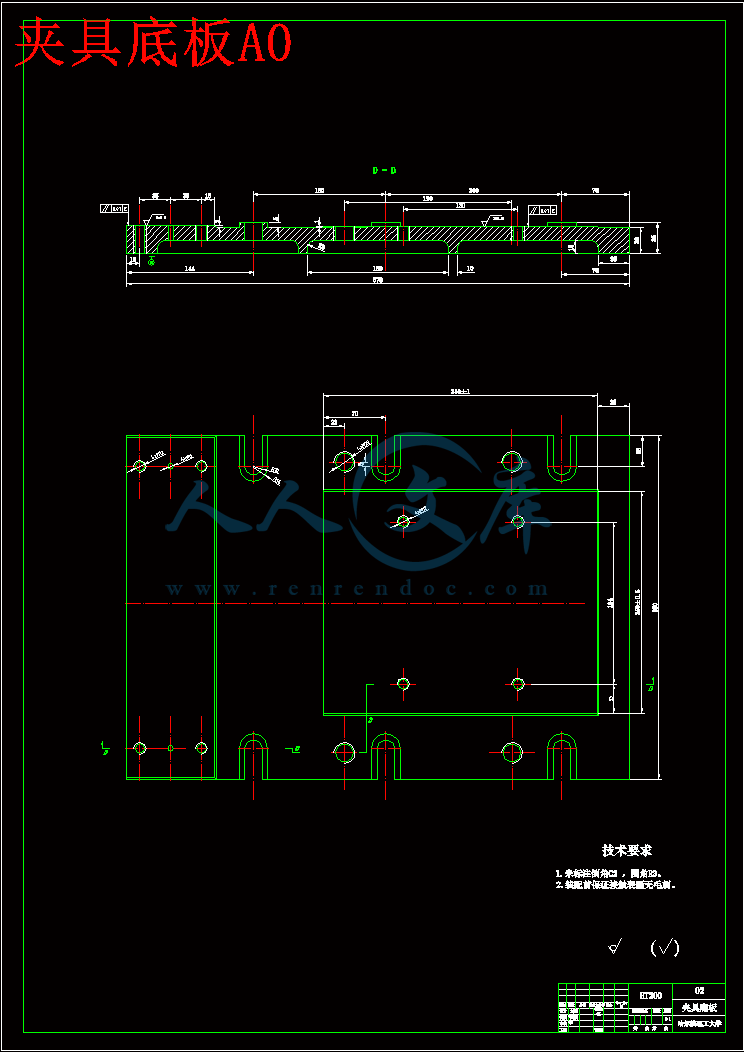
夹具底板A0.dwg

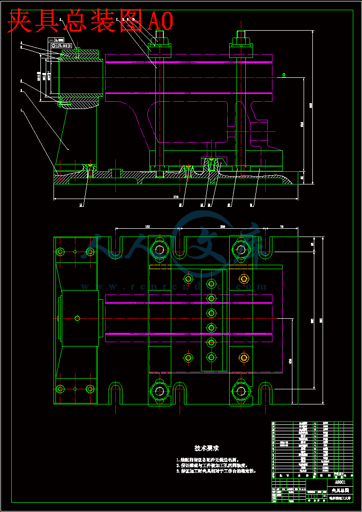
夹具总装图A0.dwg

封皮.doc

封面及封底.doc

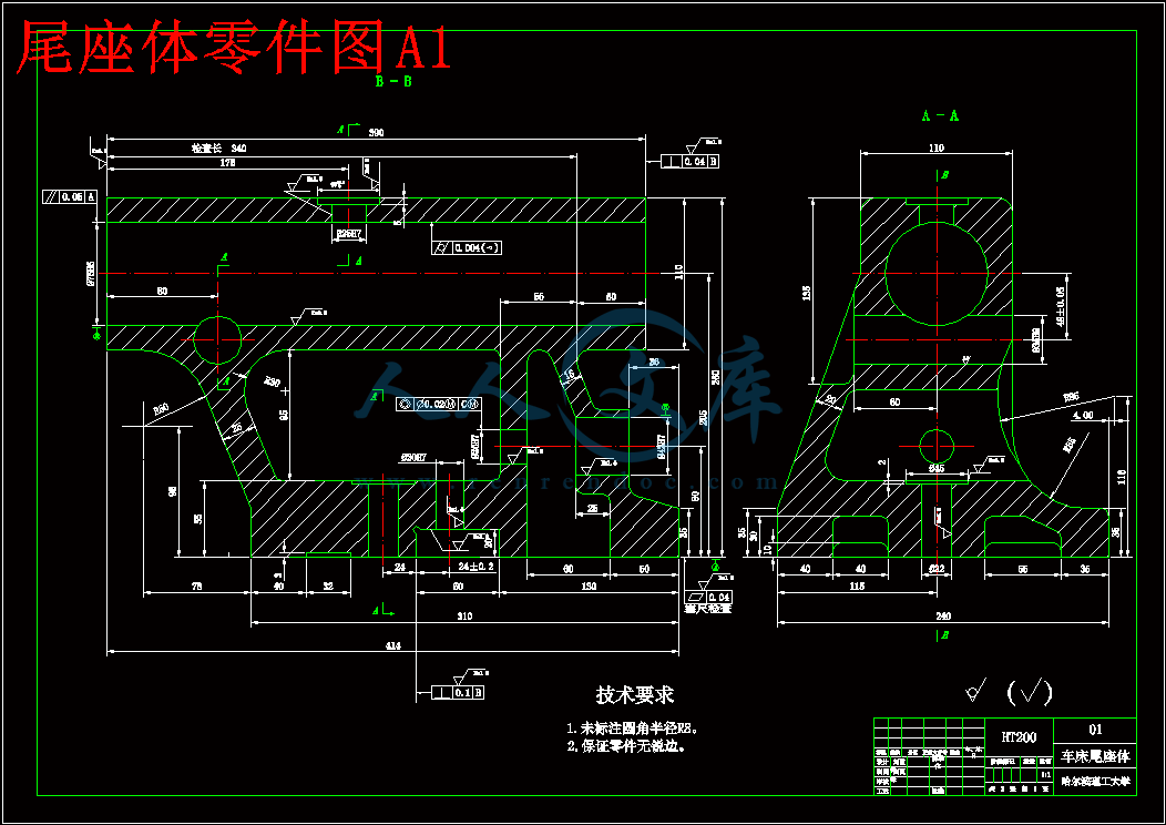
尾座体零件图A1.dwg

工序卡.doc

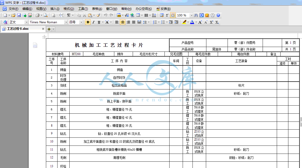
工艺过程卡.doc

评语.doc

车床尾座体工艺规程制订及工装设计开题报告.doc

车床尾座体工艺规程制订及工装设计论文.doc

零件图.JPG

车床尾座体工艺规程制订及工装设计

摘要

尾座体是车床上的重要的部件之一,是车床上用以支撑轴类零件车削加工和实施钻孔的主要车床附件。本文针对某类给定的尾座体进行了加工工艺与工装的设计,完成了以下工作:

概述了尾座体的技术和现状发展;

对尾座体进行了工艺分析,并提出了两种方案进行比较;

编制了尾座体的工艺规程,完成了其工序卡的设计;

针对工艺中的某重要工序,设计完成了一套镗孔夹具,包括定位元件,夹紧机构、对刀块、夹具体的设计并分析了定位误差。  

关键词 设计;工装;工艺;尾座体

Lather tail the craft work of the body pack a design

Abstract

   stalk spare parts, the car pares to process the main lather enclosure that drills a hole with implementation.This text aims at a certain the tail body giving certainly carried on to process the design that craft and work pack and completed once work:

   1.All said a tail the technique and present condition development of the body;

   2.Carried on craft analysis to the tail body, and put forward two kinds of projects to carry on a comparison;

   3.Drew up a tail body of craft regulations, completed the design of its work preface card;

   4.Aim at a craft in of some important work preface, designed to complete a set of Xian slot tongs, including fixed position component, clipped tight organization, to the knife piece, clip a concrete design and analyzed a fixed position error margin.  

Keywords design;  clamping;  craft;  tailstock

目录

摘要I

AbstractII

第1章 绪论1

1.1 课题来源1

1.2 课题背景及发展趋势1

1.3 夹具的基本结构及夹具设计的内容1

1.4 本章小结2

第2章 尾座体加工工艺规程设计3

2.1 零件的分析3

2.1.1 零件的作用3

2.1.2 零件的工艺分析3

2.2 加工的主要问题和工艺过程设计所应采取的相应措施4

2.2.1 确定毛坯的制造形式4

2.2.2 基面的选择4

2.2.3 确定工艺路线4

2.2.4 机械加工余量、工序尺寸及毛坯尺寸的确定5

2.2.5 确定主要工序工程中的切削用量7

2.3 本章小结17

第3章 专用夹具设计18

3.1 镗Ф75H6孔夹具设计18

3.1.1 定位基准的选择18

3.1.2 夹紧力的计算18

3.1.3 夹紧元件及动力装置确定19

3.1.4 镗套、镗模板及夹具体设计19

3.1.5 夹具精度及定位误差分析20

3.1.6 夹具设计及操作的简要说明20

3.2 本章小结22

结论23

致谢24

参考文献25

附录27

课题来源

   本课题来源于指导教师所给众多题目之一。 

课题背景及发展趋势

   加工工艺及夹具毕业设计是对所学专业知识的一次巩固,是在进行社会实践之前对所学各课程的一次深入的综合性的总复习,也是理论联系实际的训练。

   机床夹具已成为机械加工中的重要装备。机床夹具的设计和使用是促进生产发展的重要工艺措施之一。随着我国机械工业生产的不断发展,机床夹具的改进和创造已成为广大机械工人和技术人员在技术革新中的一项重要任务。

   材料、结构、工艺是产品设计的物质技术基础,一方面,技术制约着设计;另一方面,技术也推动着设计。从设计美学的观点看,技术不仅仅是物质基础还具有其本身的“功能”作用,只要善于应用材料的特性,予以相应的结构形式和适当的加工工艺,就能够创造出实用,美观,经济的产品,即在产品中发挥技术潜在的“功能”。

   技术是产品形态发展的先导,新材料,新工艺的出现,必然给产品带来新的结构,新的形态和新的造型风格。材料,加工工艺,结构,产品形象有机地联系在一起的,某个环节的变革,便会引起整个机体的变化。

   工业的迅速发展,对产品的品种和生产率提出了愈来愈高的要求,使多品种,对中小批生产作为机械生产的主流,为了适应机械生产的这种发展趋势,必然对机床夹具提出更高的要求。


夹具的基本结构及夹具设计的内容

   根据夹具设计的基本原理,选择合理的夹紧与定位方案,最有效的满足镗床夹具的设计 要求当工件的加工精度要求较高时,应采用具有固定夹具的单工位组合机床;加工精度较低时,可采用具有移动夹具的多工位组合机床。此外,还要考虑到不同布置形式的机床所能达到的加工精度。例如,对于同轴度要求较高的各孔,应采用从同一面对工件进行加工的机床布置形式。

   按在夹具中的作用,地位结构特点,组成夹具的元件可以划分为以下几类:

   1.定位元件及定位装置;

   2.夹紧元件及定位装置(或者称夹紧机构);

   3.夹具体;

   4.对刀-引导元件及装置(包括刀具导向元件,对刀装置及靠模装置等);

   5.动力装置;

   6.分度,对定装置;

   7.其它的元件及装置(包括夹具各部分相互连接用的以及夹具与机床相连接用的紧固螺钉,销钉,键和各种手柄等);

   每个夹具不一定所有的各类元件都具备,如手动夹具就没有动力装置,一般的车床夹具不一定有刀具导向元件及分度装置。反之,按照加工等方面的要求,有些夹具上还需要设有其它装置及机构,例如在有的自动化夹具中必须有上下料装置。

   专用夹具的设计主要是对以下几项内容进行设计:

   1.定位装置的设计;

   2.夹紧装置的设计;

   3.对刀-引导装置的设计;

   4.夹具体的设计;

   5.其他元件及装置的设计。 

本章小结

   通过本章陈述了尾座体加工的发展趋势以及所研究课题的主要内容,使以后的设计有了明确的针对性。

   本论文以车床尾座为模板,根据零件的特性,通过分析计算,确定加工 基准。需在多种方案中选择最优的加工工艺路线,并根据计算所得的余量选择合理的机床进行加工。最后在所有的工序中选择一道工序,做镗床夹具设计。

零件的作用

   题目所给的零件是机床尾座体,Φ75H6的孔与顶尖研配,底面与工作台相连,通过Φ20mm孔用螺栓将“尾座体”紧固在工作台上。主要作用是固定顶尖。圆柱体形的部分有一个Φ75H6孔,并且有一个Φ25孔,顶尖穿过Φ75H6孔,将螺钉拧紧,这样就将顶尖固定。  

零件的工艺分析

   “尾座体”共有三组加工表面,其中两组有位置度要求。

   1.以A为基准的加工表面。这一组表面包括110x390的上平面,两侧表面,Φ75mm孔,Φ25×5的沉头孔,Φ35H9孔以及Φ42H7孔。

   2.以B为基准的加工表面。这一组表面包括Ra=3.2μm的前端面, Ra=1.6μm的后端面,底平面60x20与32x3的槽,Φ20H7和Φ22的孔。

   3.以C为基准的加工表面。这一组表面包括Φ25H7孔。

   加工表面有位置度要求,如下:  

   底面平面度要求为0.04;Φ75H6孔圆度公差为0.004,轴线与底面平行度为0.05;后端面与Φ75H6轴线垂直度为0.04;Φ25H7孔与Φ42H7同轴度公差为0.02;底面60x20槽壁与孔Φ75H6轴线垂直度要求0.1;Φ75H6的孔需精加工、研配。  

加工的主要问题和工艺过程设计所应采取的相应措施

确定毛坯的制造形式

   零件的材料HT200。由于尾座体年产量一般为几千件,达到大批生产的水平,而且零件的轮廓尺寸较大,铸造表面质量的要求高,故可采用铸造质量稳定的,适合大批生产的金属模铸造。便于铸造和加工工艺过程,而且还可以提高生产率。 

基面的选择

   1.粗基准的选择  对于本零件而言,按照互为基准的选择原则,选择本零件的下表面作为加工的粗基准,可用装夹对肩台进行加紧,利用底面定位块支承和底面作为主要定位基准,以限制z、xz、y、xy、yz五个自由度达到定位目的。

2.精基准的选择  主要考虑到基准重合的问题,和便于装夹,采用已加工结束的上、下平面作为精基准。

确定工艺路线

表2.1工艺路线方案一

工序1粗,精镗φ75H6孔

工序2加工φ42H7孔,φ25H7孔

工序3粗,精铣上平面、侧平面

工序4粗,精铣底平面

工序5加工上平面φ25H7孔

工序6镗φ35H9侧面孔

工序7加工底平面各孔,槽

工序8去除锐边毛刺

工序9检验

表2.2工艺路线方案二

工序1粗,精铣底平面

工序2粗,精铣上平面、侧平面

工序3粗,精镗φ75H6孔

工序4加工φ42H7孔,φ25H7孔

工序5镗φ35H9侧面孔

工序6加工上平面φ25H7孔

工序7加工底平面各孔,槽

工序8去除锐边毛刺

工序9检验

   工艺路线的比较与分析:

   第二条工艺路线不同于第一条是将“镗孔工序放在除前后端面外的各面加工结束后再进行加工。其它的先后顺序均没变化。通过分析发现这样的变动提高了生产效率。而且对于零的尺寸精度和位置精度都有太大程度的帮助,并且符合先面后孔的加工原则。采用基准重合的原则,先加工底平面,然后以底平面为精基准再加工其它平面上的各孔与平面,这样便保证了Φ75H6和Φ42H7孔的轴线,同时满足了以两轴轴线为基准加工的要求。符合先加工面再钻孔的原则。若选第一条工艺路线, 加工不便于装夹,并且毛坯的端面与轴的轴线是否垂直决定了钻出来的孔的轴线与轴的轴线是非平行这个问题。所以发现第一条工艺路线并不可行。选取第二条工艺方案,先镗上、下平面,各孔,然后以这些已加工的孔为精基准,加工其它各孔,槽的形位公差要求。

   从提高效率和保证精度这两个前提下,发现第二个方案比较合理。所以我决定以第二个方案进行生产。具体的工艺过程见工艺卡片所示。  

机械加工余量、工序尺寸及毛坯尺寸的确定

   尾座体的材料是HT200,生产类型为大批生产。由于毛坯采用金属模铸造, 毛坯尺寸的确定如下:

   由于毛坯及以后各道工序或工步的加工都有加工公差,因此所规定的加工余量其实只是名义上的加工余量,实际上加工余量有最大加工余量及最小加工余量之分。

   由于本设计规定零件为大批量生产,应该采用调整法加工,因此计算最大与最小余量时应按调整法加工方式予以确定。这里就不讲述如何铸造成毛坯的过程了,只分析从毛坯加工成成品零件的过程如下:

   1.加工尾座体的底平面,底平面粗糙度要求为Ra=1.6μm,平面度要求为0.04,根据参考文献[8]表4-35和表4-37考虑3mm,粗加工2mm,精加工1mm到金属模铸造的质量和表面的粗糙度要求。最后刮研底面,保证平面度0.04。加工上平面和侧面时,用铣削的方法加工上平面和两侧面。由于上平面和两侧面的加工表面粗糙度未标注,所以按照粗糙度要求为Ra=6.3μm来加工,根据参考文献[8]表4-35和表4-37考虑2mm,粗铣加工2mm到金属模铸造的质量和表面的粗糙度要求。

   2.加工前后端面时,用铣削加工方法加工。考虑到加工方便,按照粗糙度都是Ra=1.6μm加工,根据参考文献[8]表4-35和表4-37考虑可用镗刀一次加工2mm到金属模铸造的质量和表面的粗糙度要求。因为后端面要求与基准B垂直度为0.04,所以等Φ75H6孔加工之后,再刮研保证垂直度。

   3.镗直径Φ75H6孔时,由于粗糙度要求Ra=0.8μm,因此考虑加工余量2.5mm。可一次粗加工2mm,一次精加工0.5mm就可达到要求。并且要保证从前端面开始的340mm锥度在0.04以内。

   4.加工Φ42H7孔,内壁粗糙度要求Ra=1.6μm,根据参考文献[8]表4-23考虑加工余量2.5mm。可一次钻削加工余量2mm,一次精镗0.5mm就可达到要求。以Φ42H7孔加工Φ25H7孔同轴度0.02,余量与Φ42H7孔相同。同时粗铣Φ42H7孔两个端面和Φ25H7孔的两个端面,保证各自长度值。

   5.加工Φ35H9孔,轴线距前端面为80mm,内壁粗糙度为Ra=3.2μm,根据参考文献[8]表4-23考虑加工余量2mm。可一次粗镗1.5mm,一次精镗0.5mm就可达到要求。

   6.加工上平面Φ25H7孔,先加工Φ25H7孔,内壁粗糙度要求Ra=1.6μm,根据参考文献[8]表4-23考虑加工余量1.5mm。可一次钻削加工余量1mm,一次铰孔0.5mm就可达到要求。然后锪粗糙度为Ra=6.3μm的Φ45的沉孔。

   7.加工底平面上的孔、槽,

   先分析孔的加工:

   Φ20H7孔内壁粗糙度Ra=1.6μm,根据参考文献[8]表4-23考虑加工余量1.5mm。可一次钻削加工余量1mm,一次铰孔0.5mm可达到要求

   Φ22孔及上面Φ45沉头孔粗糙度为Ra=6.3μm,一次粗加工即可完成,只需留1mm余量,需要考虑的是如何安排加工顺序,使用可调刀径的钻头,先钻削Φ22的孔,然后将刀径调大回拉,锪钻出沉头孔,最后调小刀径退刀即可。

   如前所说,在设计夹具时,应提高劳动生产率。切削力较大,为了夹紧工件,要求夹具的精度高,而这样的话将使整个夹具过于麻烦, 因此,应首先设法降低切削力,措施有二:一是提高毛坯的制造精度,使最大切削深度降低,以降低最大切削力;二是选择一种比较理想的压板压紧机构,由于自锁性比较好,故容易夹紧。因此,本夹具总的感觉还比较紧凑。对专用夹具的设计,可以了解机床夹具在切削加工中的作用,可靠地保证工件的加工精度,提高加工效率,减轻劳动强度,充分发挥和扩大机床的给以性能。本夹具设计可以反应夹具设计时应注意的问题,如定位精度、夹紧方式、夹具结构的刚度和强度、结构工艺性等问题。   目前车床尾座的生产周期相对较长,车床尾座采用铸造,不能达到其使用要求,必须经过许多步的在加工,才能满足其使用要求,在其加工过程中采用许多道工序。该课题就是为了优化加工工艺,提高加工生产效率,降低生产成本。该课题将在不降低车床尾座的使用性能的前提下采用机械加工的优化设计来达到预期目。其中本人对于对生产加工中的各个工序所需用时进行了计算,主要通过工厂请教加工工人,利用其丰富的加工经验从而使本课题更具实际的可运行性,并寻求指导老师的帮助,使得本次设计可以投入到实际的生产加工当中。

   本文对车床的机械结构进行了分析和说明,具体包含进给机构和主轴系统等核心部分的介绍。在对车床尾座的分析设计中,文章针对尾座体进行了结构设计,并进行了工艺规程文件的编制。对以后车床尾座设计计算方面的工作提供了参考,具有一定的实用价值。

   在整个设计过程中,我本着实事求是的原则,抱着科学、严谨的态度,主要按照课本的步骤,到图书馆查阅资料,在网上搜索一些相关的资料和相关产品信息,进工厂请教工人师傅,在学校征求指导老师的建议,最终完成了此次毕业设计。

参考文献

刘德荣.组合夹具结构简图的初步探讨,组合夹具,1982,15~32

孙已德.机床夹具图册.机械工业出版社,1984:20~23

贵州工学院机械制造工艺教研室.机床夹具结构图册.贵州任命出版社,1983:32~50

刘友才.机床夹具设计.机械工业出版社,1992:27~39

孟少龙.机械加工工艺手册第1卷.机械工业出版社,1991:3~10

金属机械加工工艺人员手册修订组.金属机械加工工艺人员手册.上海科学技术出版社,1979:5~25

李洪.机械加工工艺手册.机械工业出版社,1990:21~124

马贤智.机械加工余量与公差手册.中国标准出版社,1994:34~78

上海金属切削技术协会.金属切削手册.上海科学技术出版社,1984:7~23

周永强.高等学校毕业设计指导.中国建材工业出版社,2002:40~143

薛源顺.机床夹具设计(第二版) .机械工业出版社,2003:9~17

余光国,马俊,张兴发等.机床夹具设计.重庆大学出版社,1995:5~40

东北重型机械学院,洛阳农业机械学院,长春汽车厂工人大学.机床夹具设计手册.上海科学技术出版社,1980:32~46

李庆寿.机械制造工艺装备设计适用手册.宁夏人民出版社,1991:29~45

廖念钊,莫雨松,李硕根.互换性与技术测量.中国计量出版社,2000:9~19

哈尔滨工业大学,哈尔滨市教育局.专用机床夹具设计与制造.黑农江人民出版社,1979:32~42

乐兑谦.金属切削刀具.机械工业出版社,2005:4~17

哈尔滨工业大学.机床夹具设计手册.上海科学技术出版社,1983:10~69

Chernor.Machine Tools N,1984:3~18

John Louis Feirer.Machine Tool Metalworking.Glencoe/McGraw-Hill School Pub Co,1973:15~30

Manfred Weck.Handbook of Machine Tools: Automation and controls.Translated by H. Bibring.Wiley Heyden publication,1984 :12~66

Sors l.fatigue design of machine components.Oxford:pergramon press,1971:1~55


内容简介:
哈尔滨理工大学专科生毕业论文 哈尔滨理工大学荣成学院本科生毕业设计(论文)任务书学生姓名:刘国锋 学号:0930060108学 院: 荣成学院 专业:机械设计制造及其自动化任务起止时间: 2013年02月25日至 2013年06月 21日毕业设计(论文)题目:车床尾座体工艺规程制订及工装设计毕业设计工作内容:1、实际调研,收集相关资料,完成开题报告;13周。2、结合生产实际,制订零件的机械加工工艺;3、填写个工序的工序卡;47周。4、设计指定工序的专用夹具,画出装配图;811周。5、设计零件的工作图;1213周。6、撰写毕业设计论文,准备答辩;1416周。注:要求全部用计算机绘图和打印文稿(交打印件和电子稿)资料:1、机械制造工艺学;2、机床夹具设计及图册;3、金属切削用量手册;4、相关的技术资料。指导教师意见: 签名:2013年 2 月 24 日系主任意见:签名:2013年2月 25日附录Basic Machining Operations and Cutting TechnologyMachine tools have evolved from the early foot-powered lathes of the Egyptians and John Wilkinsons boring mill. They are designed to provide rigid support for both the workpiece and the cutting tool and can precisely control their relative positions and the velocity of the tool with respect to the workpiece. Basically, in metal cutting, a sharpened wedge-shaped tool removes a rather narrow strip of metal from the surface of a ductile workpiece in the form of a severely deformed chip. The chip is a waste product that is considerably shorter than the workpiece from which it came but with a corresponding increase in thickness of the uncut chip. The geometrical shape of workpiece depends on the shape of the tool and its path during the machining operation. Most machining operations produce parts of differing geometry. If a rough cylindrical workpiece revolves about a central axis and the tool penetrates beneath its surface and travels parallel to the center of rotation, a surface of revolution is produced, and the operation is called turning. If a hollow tube is machined on the inside in a similar manner, the operation is called boring. Producing an external conical surface uniformly varying diameter is called taper turning, if the tool point travels in a path of varying radius, a contoured surface like that of a bowling pin can be produced; or, if the piece is short enough and the support is sufficiently rigid, a contoured surface could be produced by feeding a shaped tool normal to the axis of rotation. Short tapered or cylindrical surfaces could also be contour formed. Flat or plane surfaces are frequently required. They can be generated by radial turning or facing, in which the tool point moves normal to the axis of rotation. In other cases, it is more convenient to hold the workpiece steady and reciprocate the tool across it in a series of straight-line cuts with a crosswise feed increment before each cutting stroke. This operation is called planning and is carried out on a shaper. For larger pieces it is easier to keep the tool stationary and draw the workpiece under it as in planning. The tool is fed at each reciprocation. Contoured surfaces can be produced by using shaped tools. Multiple-edged tools can also be used. Drilling uses a twin-edged fluted tool for holes with depths up to 5 to 10 times the drill diameter. Whether the drill turns or the workpiece rotates, relative motion between the cutting edge and the workpiece is the important factor. In milling operations a rotary cutter with a number of cutting edges engages the workpiece. Which moves slowly with respect to the cutter. Plane or contoured surfaces may be produced, depending on the geometry of the cutter and the type of feed. Horizontal or vertical axes of rotation may be used, and the feed of the workpiece may be in any of the three coordinate directions. Basic Machine Tools Machine tools are used to produce a part of a specified geometrical shape and precise I size by removing metal from a ductile material in the form of chips. The latter are a waste product and vary from long continuous ribbons of a ductile material such as steel, which are undesirable from a disposal point of view, to easily handled well-broken chips resulting from cast iron. Machine tools perform five basic metal-removal processes: I turning, planning, drilling, milling, and grinding. All other metal-removal processes are modifications of these five basic processes. For example, boring is internal turning; reaming, tapping, and counter boring modify drilled holes and are related to drilling; bobbing and gear cutting are fundamentally milling operations; hack sawing and broaching are a form of planning and honing; lapping, super finishing. Polishing and buffing are variants of grinding or abrasive removal operations. Therefore, there are only four types of basic machine tools, which use cutting tools of specific controllable geometry: 1. lathes, 2. planers, 3. drilling machines, and 4. milling machines. The grinding process forms chips, but the geometry of the abrasive grain is uncontrollable. The amount and rate of material removed by the various machining processes may be I large, as in heavy turning operations, or extremely small, as in lapping or super finishing operations where only the high spots of a surface are removed. A machine tool performs three major functions: 1. it rigidly supports the workpiece or its holder and the cutting tool; 2. it provides relative motion between the workpiece and the cutting tool; 3. it provides a range of feeds and speeds usually ranging from 4 to 32 choices in each case. Introduction of MachiningMachining as a shape-producing method is the most universally used and the most important of all manufacturing processes. Machining is a shape-producing process in which a power-driven device causes material to be removed in chip form. Most machining is done with equipment that supports both the work piece and cutting tool although in some cases portable equipment is used with unsupported workpiece. Low setup cost for small Quantities. Machining has two applications in manufacturing. For casting, forging, and press working, each specific shape to be produced, even one part, nearly always has a high tooling cost. The shapes that may he produced by welding depend to a large degree on the shapes of raw material that are available. By making use of generally high cost equipment but without special tooling, it is possible, by machining; to start with nearly any form of raw material, so tong as the exterior dimensions are great enough, and produce any desired shape from any material. Therefore .machining is usually the preferred method for producing one or a few parts, even when the design of the part would logically lead to casting, forging or press working if a high quantity were to be produced. Close accuracies, good finishes. The second application for machining is based on the high accuracies and surface finishes possible. Many of the parts machined in low quantities would be produced with lower but acceptable tolerances if produced in high quantities by some other process. On the other hand, many parts are given their general shapes by some high quantity deformation process and machined only on selected surfaces where high accuracies are needed. Internal threads, for example, are seldom produced by any means other than machining and small holes in press worked parts may be machined following the press working operations. Primary Cutting Parameters The basic tool-work relationship in cutting is adequately described by means of four factors: tool geometry, cutting speed, feed, and depth of cut. The cutting tool must be made of an appropriate material; it must be strong, tough, hard, and wear resistant. The tool s geometry characterized by planes and angles, must be correct for each cutting operation. Cutting speed is the rate at which the work surface passes by the cutting edge. It may be expressed in feet per minute. For efficient machining the cutting speed must be of a magnitude appropriate to the particular work-tool combination. In general, the harder the work material, the slower the speed. Feed is the rate at which the cutting tool advances into the workpiece. Where the workpiece or the tool rotates, feed is measured in inches per revolution. When the tool or the work reciprocates, feed is measured in inches per stroke, Generally, feed varies inversely with cutting speed for otherwise similar conditions. The depth of cut, measured inches is the distance the tool is set into the work. It is the width of the chip in turning or the thickness of the chip in a rectilinear cut. In roughing operations, the depth of cut can be larger than for finishing operations. The Effect of Changes in Cutting Parameters on Cutting Temperatures In metal cutting operations heat is generated in the primary and secondary deformation zones and these results in a complex temperature distribution throughout the tool, workpiece and chip. A typical set of isotherms is shown in figure where it can be seen that, as could be expected, there is a very large temperature gradient throughout the width of the chip as the workpiece material is sheared in primary deformation and there is a further large temperature in the chip adjacent to the face as the chip is sheared in secondary deformation. This leads to a maximum cutting temperature a short distance up the face from the cutting edge and a small distance into the chip. Since virtually all the work done in metal cutting is converted into heat, it could be expected that factors which increase the power consumed per unit volume of metal removed will increase the cutting temperature. Thus an increase in the rake angle, all other parameters remaining constant, will reduce the power per unit volume of metal removed and the cutting temperatures will reduce. When considering increase in unreformed chip thickness and cutting speed the situation is more complex. An increase in undeformed chip thickness tends to be a scale effect where the amounts of heat which pass to the workpiece, the tool and chip remain in fixed proportions and the changes in cutting temperature tend to be small. Increase in cutting speed; however, reduce the amount of heat which passes into the workpiece and this increase the temperature rise of the chip m primary deformation. Further, the secondary deformation zone tends to be smaller and this has the effect of increasing the temperatures in this zone. Other changes in cutting parameters have virtually no effect on the power consumed per unit volume of metal removed and consequently have virtually no effect on the cutting temperatures. Since it has been shown that even small changes in cutting temperature have a significant effect on tool wear rate it is appropriate to indicate how cutting temperatures can be assessed from cutting data. The most direct and accurate method for measuring temperatures in high -speed-steel cutting tools is that of Wright &. Trent which also yields detailed information on temperature distributions in high-speed-steel cutting tools. The technique is based on the metallographic examination of sectioned high-speed-steel tools which relates microstructure changes to thermal history. Trent has described measurements of cutting temperatures and temperature distributions for high-speed-steel tools when machining a wide range of workpiece materials. This technique has been further developed by using scanning electron microscopy to study fine-scale microstructure changes arising from over tempering of the tempered martens tic matrix of various high-speed-steels. This technique has also been used to study temperature distributions in both high-speed -steel single point turning tools and twist drills. Wears of Cutting Tool Discounting brittle fracture and edge chipping, which have already been dealt with, tool wear is basically of three types. Flank wear, crater wear, and notch wear. Flank wear occurs on both the major and the minor cutting edges. On the major cutting edge, which is responsible for bulk metal removal, these results in increased cutting forces and higher temperatures which if left unchecked can lead to vibration of the tool and workpiece and a condition where efficient cutting can no longer take place. On the minor cutting edge, which determines workpiece size and surface finish, flank wear can result in an oversized product which has poor surface finish. Under most practical cutting conditions, the tool will fail due to major flank wear before the minor flank wear is sufficiently large to result in the manufacture of an unacceptable component. Because of the stress distribution on the tool face, the frictional stress in the region of sliding contact between the chip and the face is at a maximum at the start of the sliding contact region and is zero at the end. Thus abrasive wear takes place in this region with more wear taking place adjacent to the seizure region than adjacent to the point at which the chip loses contact with the face. This result in localized pitting of the tool face some distance up the face which is usually referred to as catering and which normally has a section in the form of a circular arc. In many respects and for practical cutting conditions, crater wear is a less severe form of wear than flank wear and consequently flank wear is a more common tool failure criterion. However, since various authors have shown that the temperature on the face increases more rapidly with increasing cutting speed than the temperature on the flank, and since the rate of wear of any type is significantly affected by changes in temperature, crater wear usually occurs at high cutting speeds. At the end of the major flank wear land where the tool is in contact with the uncut workpiece surface it is common for the flank wear to be more pronounced than along the rest of the wear land. This is because of localised effects such as a hardened layer on the uncut surface caused by work hardening introduced by a previous cut, an oxide scale, and localised high temperatures resulting from the edge effect. This localised wear is usually referred to as notch wear and occasionally is very severe. Although the presence of the notch will not significantly affect the cutting properties of the tool, the notch is often relatively deep and if cutting were to continue there would be a good chance that the tool would fracture. If any form of progressive wear allowed to continue, dramatically and the tool would fail catastrophically, i. e. the tool would be no longer capable of cutting and, at best, the workpiece would be scrapped whilst, at worst, damage could be caused to the machine tool. For carbide cutting tools and for all types of wear, the tool is said to have reached the end of its useful life long before the onset of catastrophic failure. For high-speed-steel cutting tools, however, where the wear tends to be non-uniform it has been found that the most meaningful and reproducible results can be obtained when the wear is allowed to continue to the onset of catastrophic failure even though, of course, in practice a cutting time far less than that to failure would be used. The onset of catastrophic failure is characterized by one of several phenomena, the most common being a sudden increase in cutting force, the presence of burnished rings on the workpiece, and a significant increase in the noise level. Mechanism of Surface Finish Production There are basically five mechanisms which contribute to the production of a surface which have been machined. These are:1The basic geometry of the cutting process. In, for example, single point turning the tool will advance a constant distance axially per revolution of the workpiecc and the resultant surface will have on it, when viewed perpendicularly to the direction of tool feed motion, a series of cusps which will have a basic form which replicates the shape of the tool in cut. 2The efficiency of the cutting operation. It has already been mentioned that cutting with unstable built-up-edges will produce a surface which contains hard built-up-edge fragments which will result in a degradation of the surface finish. It can also be demonstrated that cutting under adverse conditions such as apply when using large feeds small rake angles and low cutting speeds, besides producing conditions which lead to unstable built-up-edge production, the cutting process itself can become unstable and instead of continuous shear occurring in the shear zone, tearing takes place, discontinuous chips of uneven thickness are produced, and the resultant surface is poor. This situation is particularly noticeable when machining very ductile materials such as copper and aluminum. 3The stability of the machine tool. Under some combinations of cutting conditions; workpiece size, method of clamping ,and cutting tool rigidity relative to the machine tool structure, instability can be set up in the tool which causes it to vibrate. Under some conditions this vibration will reach and maintain steady amplitude whilst under other conditions the vibration will built up and unless cutting is stopped considerable damage to both the cutting tool and workpiece may occur. This phenomenon is known as chatter and in axial turning is characterized by long pitch helical bands on the workpiece surface and short pitch undulations on the transient machined surface. 4The effectiveness of removing swarf. In discontinuous chip production machining, such as milling or turning of brittle materials, it is expected that the chip (swarf) will leave the cutting zone either under gravity or with the assistance of a jet of cutting fluid and that they will not influence the cut surface in any way. However, when continuous chip production is evident, unless steps are taken to control the swarf it is likely that it will impinge on the cut surface and mark it. Inevitably, this marking besides looking. 5The effective clearance angle on the cutting tool. For certain geometries of minor cutting edge relief and clearance angles it is possible to cut on the major cutting edge and burnish on the minor cutting edge. This can produce a good surface finish but, of course, it is strictly a combination of metal cutting and metal forming and is not to be recommended as a practical cutting method. However, due to cutting tool wear, these conditions occasionally arise and lead to a marked change in the surface characteristics. Limits and Tolerances Machine parts are manufactured so they are interchangeable. In other words, each part of a machine or mechanism is made to a certain size and shape so will fit into any other machine or mechanism of the same type. To make the part interchangeable, each individual part must be made to a size that will fit the mating part in the correct way. It is not only impossible, but also impractical to make many parts to an exact size. This is because machines are not perfect, and the tools become worn. A slight variation from the exact size is always allowed. The amount of this variation depends on the kind of part being manufactured. For examples part might be made 6 in. long with a variation allowed of 0.003 (three-thousandths) in. above and below this size. Therefore, the part could be 5.997 to 6.003 in. and still be the correct size. These are known as the limits. The difference between upper and lower limits is called the tolerance. A tolerance is the total permissible variation in the size of a part. The basic size is that size from which limits of size arc derived by the application of allowances and tolerances. Sometimes the limit is allowed in only one direction. This is known as unilateral tolerance.Unilateral tolerancing is a system of dimensioning where the tolerance (that is variation) is shown in only one direction from the nominal size. Unilateral tolerancing allow the changing of tolerance on a hole or shaft without seriously affecting the fit.When the tolerance is in both directions from the basic size it is known as a bilateral tolerance (plus and minus). Bilateral tolerancing is a system of dimensioning where the tolerance (that is variation) is split and is shown on either side of the nominal size. Limit dimensioning is a system of dimensioning where only the maximum and minimum dimensions arc shown. Thus, the tolerance is the difference between these two dimensions. 基本加工工序和切削技术机床是从早期的埃及人的脚踏动力车和约翰威尔金森的镗床发展而来的。它们为工件和刀具提供刚性支撑并可以精确控制它们的相对位置和相对速度。基本上讲,金属切削是指一个磨尖的锲形工具从有韧性的工件表面上去除一条很窄的金属。切屑是被废弃的产品,与其它工件相比切屑较短,但对于未切削部分的厚度有一定的增加。工件表面的几何形状取决于刀具的形状以及加工操作过程中刀具的路径。大多数加工工序产生不同几何形状的零件。如果一个粗糙的工件在中心轴上转动并且刀具平行于旋转中心切入工件表面,一个旋转表面就产生了,这种操作称为车削。如果一个空心的管子以同样的方式在内表面加工,这种操作称为镗孔。当均匀地改变直径时便产生了一个圆锥形的外表面,这称为锥度车削。如果刀具接触点以改变半径的方式运动,那么一个外轮廓像球的工件便产生了;或者如果工件足够的短并且支撑是十分刚硬的,那么成型刀具相对于旋转轴正常进给的一个外表面便可产生,短锥形或圆柱形的表面也可形成。平坦的表面是经常需要的,它们可以由刀具接触点相对于旋转轴的径向车削产生。在刨削时对于较大的工件更容易将刀具固定并将工件置于刀具下面。刀具可以往复地进给。成形面可以通过成型刀具加工产生。多刃刀具也能使用。使用双刃槽钻钻深度是钻孔直径5-10倍的孔。不管是钻头旋转还是工件旋转,切削刃与工件之间的相对运动是一个重要因数。在铣削时一个带有许多切削刃的旋转刀具与工件接触,工件相对刀具慢慢运动。平的或成形面根据刀具的几何形状和进给方式可能产生。可以产生横向或纵向轴旋转并且可以在任何三个坐标方向上进给。基本机床机床通过从塑性材料上去除屑片来产生出具有特别几何形状和精确尺寸的零件。后者是废弃物,是由塑性材料如钢的长而不断的带状物变化而来,从处理的角度来看,那是没有用处的。很容易处理不好由铸铁产生的破裂的屑片。机床执行五种基本的去除金属的过程:车削,刨削,钻孔,铣削。所有其他的去除金属的过程都是由这五个基本程序修改而来的,举例来说,镗孔是内部车削;铰孔,攻丝和扩孔是进一步加工钻过的孔;齿轮加工是基于铣削操作的。抛光和打磨是磨削和去除磨料工序的变形。因此,只有四种基本类型的机床,使用特别可控制几何形状的切削工具1.车床,2.钻床,3.铣床,4.磨床。磨削过程形成了屑片,但磨粒的几何形状是不可控制的。通过各种加工工序去除材料的数量和速度是巨大的,正如在大型车削加工,或者是极小的如研磨和超精密加工中只有面的高点被除掉。一台机床履行三大职能:1.它支撑工件或夹具和刀具2.它为工件和刀具提供相对运动3.在每一种情况下提供一系列的进给量和一般可达4-32种的速度选择。机械加工介绍作为产生形状的一种方法,机械加工是所有制造过程中最普遍使用的而且是最重要的方法。机械加工过程是一个产生形状的过程,在这过程中,驱动装置使工件上的一些材料以切屑的形式被去除。尽管在某些场合,工件无支承情况下,使用移动式装备来实现加工,但大多数的机械加工是通过既支承工件又支承刀具的装备来完成。小批量,低成本。机械加工在制造业上有两个应用。是铸造,锻造和压力工作,产生每一个特殊形状,甚至一个零件,几乎总有较高的模具成本。焊接的形状很大程度上取决于原材料。通过利用总成本高但没有特殊模具的设备,加工是有可能的;从几乎任何形式的原材料开始,只要外部尺寸足够大,由任意材料设计形状。因此加工是首选的方法,当生产一个或几个零件甚至在大批量生产时,零件的设计在逻辑上导致铸造,锻造或冲压制品 。高精度,表面精度。机械加工的第二个应用是基于可能的高精度和表面精度的。如果在其他工序中大批量生产,很多低量零件会产生出低的但可接受的公差。另一方面,许多零件由一些大变形过程产生一般的形状,并且只在具有很高精度的选定面加工。举例来说,内线流程是很少产生任何方式以外的其他机械加工并且紧接着压力操作后零件上的小洞可能被加工。主要的切削参数在切削时基本工具工作的关系充分描述的方法有4个因素:刀具几何形状,切削速度和切削深度。刀具必须由适当的材料做成;它必须有一定的强度,粗糙度,硬度和抗疲劳度。刀具几何形状由面和角度描述,对每一种切削操作都是正确的。切削速度是指切削刃通过工作面的速度,它已每分钟通过的英尺数表示。对于加工效率,切削速度相对于特殊工作组合必须具有适当规模。一般来讲,工件越硬,速度越小。进给是刀具进入工件的速率。当工件或刀具旋转时,进给量的单位是英寸每转。当刀具或工件往复移动时,进给量的单位是英寸没次,总的来说,在其他相似情况下进给量与切削速度成反比。切削速度用英寸表示,是刀具进入工件的距离表示的,它是指车削时屑片的宽度或是直线切削时屑片的厚度。粗加工时切削深度比精加工的切削深度大。切削参数的改变对切削温度的影响在金属切削作业中热量产生于主要和第二变形区而这些结果导致了复杂温度遍布于刀具,工件和屑片。一个典型的等温先如图所示,它可以看出正如预测的,当工件材料经历主要变形,被减切时,有一个非常大温度梯度遍布于屑片的整个宽度。当第二
温馨提示:
1: 本站所有资源如无特殊说明,都需要本地电脑安装OFFICE2007和PDF阅读器。图纸软件为CAD,CAXA,PROE,UG,SolidWorks等.压缩文件请下载最新的WinRAR软件解压。
2: 本站的文档不包含任何第三方提供的附件图纸等,如果需要附件,请联系上传者。文件的所有权益归上传用户所有。
3.本站RAR压缩包中若带图纸,网页内容里面会有图纸预览,若没有图纸预览就没有图纸。
4. 未经权益所有人同意不得将文件中的内容挪作商业或盈利用途。
5. 人人文库网仅提供信息存储空间,仅对用户上传内容的表现方式做保护处理,对用户上传分享的文档内容本身不做任何修改或编辑,并不能对任何下载内容负责。
6. 下载文件中如有侵权或不适当内容,请与我们联系,我们立即纠正。
7. 本站不保证下载资源的准确性、安全性和完整性, 同时也不承担用户因使用这些下载资源对自己和他人造成任何形式的伤害或损失。
提示  人人文库网所有资源均是用户自行上传分享,仅供网友学习交流,未经上传用户书面授权,请勿作他用。
关于本文
本文标题:车床尾座体工艺规程制订及工装设计【镗孔Ф75H6】【3张CAD图纸】【优秀】
链接地址:https://www.renrendoc.com/p-293135.html

官方联系方式

2:不支持迅雷下载,请使用浏览器下载   
3:不支持QQ浏览器下载,请用其他浏览器   
4:下载后的文档和图纸-无水印   
5:文档经过压缩,下载后原文更清晰   
关于我们 - 网站声明 - 网站地图 - 资源地图 - 友情链接 - 网站客服 - 联系我们

网站客服QQ:2881952447     

copyright@ 2020-2025  renrendoc.com 人人文库版权所有   联系电话:400-852-1180

备案号:蜀ICP备2022000484号-2       经营许可证: 川B2-20220663       公网安备川公网安备: 51019002004831号

本站为文档C2C交易模式,即用户上传的文档直接被用户下载,本站只是中间服务平台,本站所有文档下载所得的收益归上传人(含作者)所有。人人文库网仅提供信息存储空间,仅对用户上传内容的表现方式做保护处理,对上载内容本身不做任何修改或编辑。若文档所含内容侵犯了您的版权或隐私,请立即通知人人文库网,我们立即给予删除!