顶出板.dwg
顶出板.dwg

通风盖板模具设计及装配过程的动画设计【带PROE三维+动画仿真】【11张CAD图纸】

收藏

资源目录
跳过导航链接。
通风盖板模具设计及装配过程的动画设计【带PROE三维+动画仿真】【11张CAD图纸】.rar
顶出板.dwg---(点击预览)
顶出固定板.dwg---(点击预览)
通风盖板模具设计及装配过程的动画设计论文.doc---(点击预览)
装配图.dwg---(点击预览)
支柱.dwg---(点击预览)
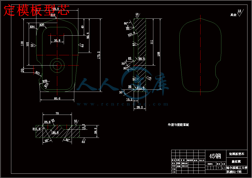
定模板型芯.dwg---(点击预览)
定模板.dwg---(点击预览)
定模固定板.dwg---(点击预览)
外文翻译--注塑模的温度调节系统.doc---(点击预览)
垫板.dwg---(点击预览)
动模板型芯.dwg---(点击预览)
动模板.dwg---(点击预览)
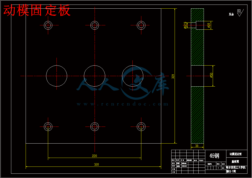
动模固定板.dwg---(点击预览)
任务书.doc---(点击预览)
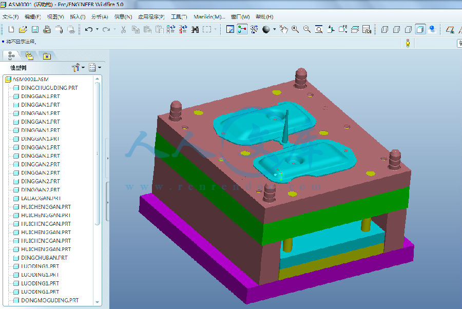
PROE三维图+动画仿真
003.prt.1
asm0001.asm.10
ASM0001.mpg
asm0002.asm.4
asm0002.asm.5
ASM0002.mpg
asm0003.asm.5
asm0003.asm.6
asm0003.asm.7
cajian1.prt.3
cajian2.prt.1
current_session.pro
daotao.prt.1
daozhu.prt.2
dianban.prt.11
dingchuban.prt.4
dingchuguding.prt.16
dingchuguding.prt.17
dinggan1.prt.2
dinggan2.prt.2
dingmoban.prt.2
dingmoban.prt.3
dingmoguding.prt.9
dongmoguding.prt.4
dongnoban.prt.4
drw0001.bak
drw0001_dwg__out.log.1
huichenggan.prt.1
jiaokoutao.prt.5
jiaokoutao.prt.6
laliaogan.prt.2
laliaogan.prt.3
luoding1.prt.3
luoding2.prt.5
luoding3.prt.3
prt0006.prt.1
results.rep
std.out
trail.txt.1
xingxin.prt.1
xingxin1.prt.5
xingxin2.prt.6
yuanzhuxiao.prt.2
zhizhu.prt.4
压缩包内文档预览:
预览图
编号:293233    类型:共享资源    大小:11.51MB    格式:RAR    上传时间:2014-06-24 上传人:上*** IP属地:江苏
50
积分
关 键 词:
通风盖板 模具设计 装配过程 动画设计 proe三维 动画仿真 cad 图纸
资源描述:

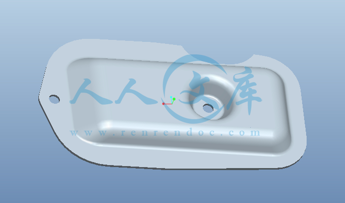
通风盖板模具设计及装配过程的动画设计

38页 15000字数+说明书+任务书+PROE三维图+动画仿真+11张CAD图纸【详情如下】

PROE三维图+动画仿真

任务书.doc

动模固定板.dwg

动模板.dwg

动模板型芯.dwg

垫板.dwg

外文翻译--注塑模的温度调节系统.doc

定模固定板.dwg

定模板.dwg

定模板型芯.dwg

支柱.dwg

装配图.dwg

通风盖板模具设计及装配过程的动画设计论文.doc

顶出固定板.dwg

顶出板.dwg

通风盖板模具设计及装配过程的动画设计

摘要

   目前塑料在实现“以塑代钢”方面起着不可忽视的作用,它正以其物美价廉的特征渗透到国民经济的各个领域。工程塑料制品的速度增长率为每年10%,然而在工程塑料中70%—80%以上的制品是采用注塑成型加工。如今塑料制品广泛应用于广泛应用于电子、机械、汽车、航天、家电、玩具等各个行业。因此也使注塑模具的设计与制造带来了繁荣的景象。在模具设计中,Pro/E软件以它强大的实体建模功能和结构分析功能扮演着不可或缺的角色。

本文简要概述了CAD技术在国内外的发展状况,介绍了CAD在模具工业中的使用和发展情况,介绍了在我国研究和发展模具CAD技术的必要性和迫切性, 介绍了Pro/E软件的一些模块及其功能,介绍模具与注射机的关系等,并图文并茂介绍了利用Pro/E软件进行模具设计的整个过程。涵盖主题包括:模具型腔设计,浇注系统设计,脱模机构设计,温度调节系统设计, 开模模拟等知识面。

   在英文翻译中,我将对国内资料没有详细介绍的温度调节系统作了介绍。

关键词 :塑料;模具;CAD技术;Pro/E

The Design of the Ventilates Lap Mold and the Animation of the Assembly Process

Abstract

   At present the plastic is playing the noticeable role in realizing "by plastic instead of steel" aspect. It is famous as its excellent in Quality and reason able in price characteristic and infiltrate to each domain of national economy. Engineering plastics go up by the ratio of 10% each year, however 70% - 80% above product isuses in the engineering plastics casts takes shape the processing. Now the plastic product widely applies in the domain of the electron, the machinery, the automobile, astronautics, the electrical appliances, the toy and so on. Therefore the design and the manufacture about the mold has broad foreground In mold design, Pro/E software is playing the indispensable role in its formidableentity modelling function and the structure analysis function.

   This article has briefly outlined the development condition of the CAD technology in the domestic and foreign , introduced  the use and development situation of the CAD  in the mold industry ,introduced  the necessity and urgency that develop and study mold CAD technology in our country, introduced some modules and its the function of the Pro/E software , introduced the relationship of the mold and the injection machine and  introduced the entire processuses which realize the mold designs using the Pro/ E software abundantly and elegantly. The design subject includes: the design of mold cavity, the design of pours system, the design of drawing of patterns organization, the control system design about temperature, simulation of opening mold and so on.

  In English translation, I have made the introduction to temperature control system that the domestic material not detailed introduction.  

Keywords :plastic; Injection Mold; CAD technology; Pro/E

不要删除行尾的分节符,此行不会被打印

目录

摘要I

AbstractII

第1章 绪论1

1.1 课题背景1

1.2 塑料注射模具CAD综述1

1.3 塑料注射模具CAD的特点2

1.4 计算机在塑料注射模具设计与制造中的应用2

1.5 现代模具技术发展3

1.6 新一代模具设计软件技术4

1.7 Pro/ENGINEER软件介绍4

第2章 注塑零件的设计6

2.1 材料特性6

2.1.1 使用性能6

2.1.2 成型性能6

2.2 塑料制品结构设计6

第3章 模具设计8

3.1 塑料的成型工艺特性8

3.2 注射机的选择9

3.3 模具材料的选择11

3.4 模具加工工艺12

3.5 注射模具设计13

3.5.1 成型零件结构设计14

3.5.2 浇注系统设计23

3.5.3 导向机构的设计25

3.5.4 排气系统设计26

3.5.5 脱模机构设计27

3.5.6 温度调节系统设计30

结论32

致谢33

参考文献34

附录35

课题背景


塑料注射模具CAD综述

   产品的制造工艺过程都必须先进行设计,设计工作是新产品研制的第一步。设计工作的水平直接关系到新产品质量性能、研制周期和技术经济效益。手工设计,设计人员必须查阅大量的技术资料和设计手册,根据本单位和有关企业的技术资料,通过理论计算和实验分析,把设计思想用图纸和说明书表达出来后,再与有关工程人员讨论、修改。在整个设计过程中.设计人员花费了大量的时间在绘图和查阅资料上,造成智力和时间的浪费,这远远不能适应当今生产的发展。随着计算机的发展,为了提高设计效率和质量,CAD应运而生了。

   CAD是二十世纪下半叶最重要的技术成果之一,其应用水平往往体现一个国家(地区)的科学技术水平,现已广泛应用在各个行业和部门。模具行业是应用计算机辅助设计最多,并同时也是最能体现CAD优越性的部门之一。

   随着科学技术的发展,模具行业在国民经济中的地位日益提高、重要性日趋明显。传统的模具设计与制造方法己不能适应工业产品的迅速更新换代和提高质量的要求。因此,国外工业发达的国家对模具CAD和模具CAM技术的开发非常重视。早在二十世纪六十年代,国外一些飞机制造公司就开始了CAD和CAM的研究工作。

   工业发达国家较大的模具生产厂家在模具CAD/CAM上进行了较大投资,正大力开发研究这一技术。如法国的FOS模具公司己购买了大型CAD/CAM系统,日本、美国、德国等国家也己开发CAD/CAM系统,并广泛应用于模具制造。

   我国模具CAD/CAM的开发开始于二十世纪七十年代末。虽然起步较晚,但发展迅速。到目前为止,先后经过国家有关部门鉴定的有精冲模、普通冲裁模、辊锻模、锤模和塑料注射模等,但这些系统大多数仍处于研究开发阶段,被推广生产使用并形成商品化的不多。近几年来华中理工大学、上海交通大学、合肥工业大学、北京航空航天大学等高等院校对模具CAD进行了卓有成效的研究。其中华中理工大学研究开发的HSC2.0注射模CAD/CAM/CAE系统,己受到川门的重视。它是在Auto CAD软件的基础上,采用Auto CAD提供的ADS开发平台用C语言编写的。它除了具有Auto CAD本身的功能外,还具有模具结构设计子系统、结构及工艺参数计算校核子系统、塑料注射流动、保压与冷却模拟子系统、数控线切割编程子系统、建库工具和设计进程管理等模块。所有程序均能在Auto CAD的环境中集成运行。

塑料注射模具CAD的特点

   塑料注射模具设计的特点主要是:

   1.外部约束多

   即根据制品及生产厂家的要求,对成型制品的材料性能、成型工艺条件、模具结构、使用设备等都要进行充分的考虑。但主要的还是要考虑塑料制品的形状结构、尺寸大小以及由此带来的模具结构问题。如成型零件的结构、顶出方式、排气形式、冷却回路的布置等。

   2.模具结构复杂且灵活

   注射模具包括浇注系统、成型零部件、脱模系统、导向系统、冷却系统、排气系统等组成。每一系统都有各自的结构形式,且结构形式由于加工制造方法、加工设备等的不同又有所区别,因此在设计中没有固定的准则,不同的设计人员对同一制品可能有多种结构设计,灵活性很大。

   因此,针对上述特点反映到模具CAD系统的开发方面,要求系统具有功能丰富、流程复杂、交互性强、用户界面友好等特点。

   塑料注射模具CAD技术主要从两个方面对模具设计人员提供强有力的帮助:一是模具结构CAD;二是模具CAE。

   模具结构CAD包括模具总体结构方案设计和零部件设计,数控仿真和数控程序的生成,模具装配模拟,零件图和装配图的生成与绘制等方面。

计算机在塑料注射模具设计与制造中的应用

   塑料注射模具的设计与制造是一个十分复杂的过程。它包括产品的概念设计、模具总体方案设计、模具结构设计、模具零件制造加工、模具装配以及制品生产等多个环节,在模具设计阶段还要进行有关部件的分析模拟与校核。传统的模具设计与制造方法难以全面考虑这些所有的环节。现在,计算机己应用于上述的各个环节。借助于计算机这一强有力的工具和CAD这一先进技术,可以把这些环节有机地结合起来。下面主要论述模具总体方案设计和分析模拟过程中计算机CAD的应用。

    1.模具总体方案设计阶段

   该阶段主要是根据塑料制品的要求,考虑成型型腔的数量、镶件的材料、浇注系统、冷却系统、脱模系统以及侧向分型系统的结构形式,选择模架类型、规格以及对注射设备的要求等。模具总体方案设计属概念设计范畴,对整个设计过程和设计结果具有决定性影响。但是,其经验性强,需要考虑多方面的因素和要求。因此,对设计人员的要求高.此外,由于模具结构的复杂性,总体方案的设计往往要经过反复修改,是一个逐步寻优的过程。

   模具总体方案设计CAD系统,为模具设计人员表达设计构思和反复修改设计方案提供了有效的手段,从而提高了设计结果的合理性和设计效率。人们对模具结构CAD的柔性技术进行了研究,提出了有关装配模型、虚零件和符号零件等不同方案,并开发出一些注射模具总体方案设计的CAD系统。

现在,KBS技术(基于知识的系统,Knowledge-Based System)在模具总体方案设计方面的应用,己成为一个重要的研究课题。这种技术应用知识库中的设计知识,从塑料产品应用需求、所用塑料的特性和工艺特征出发,经过逐步推理得出模具结构的各部分方案,从而得到总体设计方案。模具结构总体方案确定后,通过数控加工模块生成模具零件的数控加工程序,实现了设计CAI〕与制造CAM两个过程的连接,从而加快了模具设计与制造的周期。

   2.分析模拟

对于精密、大型的塑料注射模具,其成型过程是一个复杂的过程。在以往的模具设计中,设计人员的经验起着十分重要的作用。但也经常会进行反复的试模和修模,以不断修整模具的不合理部分。但这样会造成制造周期的延长和模具本身质量的下降。

现代模具技术发展?

   模具设计是一个多环节的复杂过程,从初始化到最后的装配检测,实质上是将产品的设计信息在生产环节间进行不间断传送与处理并反馈的过程,正确的模具设计方法应该是并行工程的方法,是实现模具CAD等各个模具间信息的提取、交换和处理的集成化,必须建立模具集成化的产品信息模型。采用基于特征变量化设计,工程数据库管理系统等技术已成为目前研究的热门。

   运用计算机辅助设计技术进行实物零件到实物的整个复杂过程称为反演化工程,采用反演化技术,可迅速将事物CAD模型化,再利用已有的模具CAD系统进行模具设计,具有速度快等优点,同时它使模具设计的流程由传统的开环结构向闭环结构转变:制件----模具设计----模具设计----制件同原件进行比较调整,从而建立模具质量保证体系。利用和集成各种计算机技术,网络为通讯手段,协调企业的各种行为以获得好的经济效益为目标来设计产品,模具作为一种特殊的行业无疑要向计算机化方向发展,这是未来模具设计总的发展趋势。

新一代模具设计软件技术

   新一代模具软件是建立在模具设计实践中归纳总结出来的大量知识上。具有智能化意义 。在智能化软件的支持下,CAD不在是对传统设计与计算方法的模仿,而是在先进设计理论的指导下,充分运用本领域专家的丰富知识和成功经验,其设计结果必然具有合理性和先进性 。

   新一代模具软件以立体的思想,直观的感觉来设计模具结构,所以生成的三维结构信息能方便地用于模具可制造性评价和数控加工,在三维参数化特征造型、成型过程模拟、数据加工过程仿真以及信息流的组织与管理方面已达到相当完善的程度并具有较高的集成化水平。

新一代软件已能具有面向装配的功能,因为模具的功能还有通过装配结果才能体现出来,而新一代模具软件可为模具设计人员提供多种途径来建立模具的装配模型。采用南向装配的设计方法后,模具装配不在是几个零件的简单拼装,起数据结构既能描述模具的功能,又可定义模具零部件间相互关系的装配特征,实现零部件的关联,因而能有效地保证模具的质量,目前,车内模具企业中已有相当多的厂家引进了较高档次的CAD/CAM/CAE系统,诸多软件在中车模具工业中应用。

Pro/ENGINEER软件介绍

   随着模具技术的发展,涌现出了很多设计和制造模具的优秀的软件。有:CADAM软件包(Computer-graphics Augmented Design and Manufacturing,计算机图形增强设计与制造)、CATIA软件包(Computer-Graphics Aided Three-Dimensional Interactive Applications,计算机辅助三维图形交互应用软件包)、Autodesk公司的AutoCAD系统、EDS公司的Unigraphics系统、PTC公司的Pro/ENGINEER系统。这些软件的出现,使模具的设计和制造过程变的更为方便和快捷。本设计采用的软件是Pro/ENGINEER。

   Pro/ENGINEER自1988年问世以来,10年间已成为全世界及中国地区最普及的3D、 CAD/CAM系统。Pro/ENGINEER在今日俨然成为世界3D CAD/CAM系统的标准软件,广泛应用于电子、机械、模具、工业设计、汽机车、自行车、航天、家电、玩具等各行业。Pro/ENGINEER可谓是个全方位的3D产品开发软件,集合了零件设计、产品组合、模具开发、NC加工、钣金件设计、铸造件设计、造型设计、逆向工程、自动测量、机构仿真、应力分析、产品数据库管理等功能于一体。

   Pro/ENGINEER是一套由设计至生产的机械自动化软件,是新一代的产品造型系统,是一个参数化、基于特征的实体造型系统,并且具有单一数据库功能。

   1.参数化设计和特征功能

   Pro/ENGINEER是采用参数化设计的、基于特征的实体模型化系统,工程设计人员采用具有智能特性的基于特征的功能去生成模型,如腔、壳、倒角及圆角,您可以随意勾画草图,轻易改变模型。这一功能特性给工程设计者提供了在设计上从未有过的简易和灵活。

   2. 单一数据库

   Pro/ENGINEER是建立在统一基层上的数据库上,不象一些传统的CAD/CAM系统建立在多个数据库上。所谓单一数据库,就是工程中的资料全部来自一个库,使得每一个独立用户在为一件产品造型而工作,不管他是哪一个部门的。换言之,在整个设计过程的任何一处发生改动,亦可以前后反应在整个设计过程的相关环节上。例如,一旦工程详图有改变,NC(数控)工具路径也会自动更新;组装工程图如有任何变动,也完全同样反应在整个三维模型上。这种独特的数据结构与工程设计的完整的结合,使得一件产品的设计结合起来。这一优点,使得设计更优化,成品质量更高,产品能更好地推向市场,价格也更便宜。

   Pro/ENGINEER具有包括Pro/DESIGN、Pro/MECHANICAL、Pro/MOLDESIGN等27个模块,本设计使用的主要是Pro/DESIGN、Pro/MOLDESIGN模块。Pro/MOLDESIGN模块用于设计模具部件和模板组装,它包括如下功能:

   (1) 采用参照设计模型的方法,自动生成模具型腔几何体。

   (2) 对单一、多面类似或者多面不同的型腔,采用 Pro/ENGINEER的组装命令及花样组来定出型腔。

   (3) 对复杂的多面/注模,提供 Slider/CAMMED移动功能。

   (4) 用不同的缩减补偿方式,修改造型几何体。

   (5) 在模拟过程,采用干扰核查的方法支定度及模似模具开口及 Molding Ejection Sequence.

   (6) 备有 AC Technology的 C—Flow/EZ分析软件,提供空腔冲填及 AIR TRAPPING模拟、 Front、ram速度、weld线及流体速度(Flow)。

   (7) 直接取得 Pertinent模具设计工程的信息,包括冲填器皿及型腔表面积等信息。

   (8) 可生成模具的特定功能,包括浇口(Sprue)、浇道(Runner)、浇槽(Gates)、冷凝线(cooling line)及分离线。

   (9)标准化的模具组装及元件。

参考文献

1. 申树义 高济 .塑料模具设计. 机械工业出版社. 2003年;

2.塑料模具技术手册编委会编. 塑料模具技术手册. 机械工业出版社.1997年;

3.陈万林等 .实用塑料注射模设计与制造. 机械工业出版社.2000年;

4.詹友刚.Pro/ENGINEER中文野火版教程——通用模块.清华大学出版社. 2004. 年;

5.陆宁编.实用注塑模具设.  中国轻工业出版社.  1997年;

6.许发越 .模具标准应用手册.  机械工业出版社 .1994年;

7.郭芝俊,邱宣怀.机械设计.高等教育出版社.1990年;

8.林清安.Pro/ENGINEER零件设计基础篇(上、下) .北京大学出版社,1999年;

9.林清安.Pro/ENGINEER零件组合.北京大学出版社 .2000年;

10.郭芝俊,邱宣怀.机械设计.高等教育出版社 .1990年;

11.冯炳尧 韩太荣 殷振海 蒋文森. 模具设计与制造简明手册 .上海科学技术出版社 .1992年;

12.Alan pugh “Injection mould design and manufacture” IFS(Publication)Ltd.HK 1986;

13.R.Paul “Plastics process technology” The MIT Press  1981。


内容简介:
哈尔滨理工大学毕业设计(论文)任务书学生姓名: 祝加贝 学号:1030060125学 院: 荣成学院 专业:机械设计制造及其自动化任务起止时间: 2014年02月24日至 2013年06月 20日毕业设计(论文)题目:通风盖板模具设计及装配过程的动画设计毕业设计工作内容:1、翻译外文资料、资料准备和写开题报告(第1至第3周);2、结合生产实际,制订零件的加工工艺,并进行相应的工艺参数计算;(第4至第6周);3、设计所有的模具,画出装配图以及所有零件的工作图;(第7至第11周);4、模具加工过程的动画设计(第12至第14周);5、攥写毕业论文,准备答辩;(第15周第16周)注:要求全部用计算机绘图和打印文稿(交打印件和电子稿)资料:1、机械制造工艺学;2、模具设计及图册;3、机械设计手册手册;4、相关的技术资料。5、Pro/ENGINEER相关资料;指导教师意见: 签名:2014年 02 月20 日系主任意见:签名:2014年02月22日教务处制表教务处制表附录外文资料TEMPERATURE CONTROL P. H. J. Ingham Marketing Manager ,Eurotherm Ltd,Worthing,Sussex,UK SUMMARYCommercial plastic materials are organically based and are therefore heatsensitive .Accurate temperature control of melt processes such as injection moulding is therefore necessary if problems caused by thermal degradation are to be avoided.The injection moulding process is considered form a temperature controlriewpoint and some of the control methods or techniques are described.since it should not be forgotten that good temperature control can lend to materials and energy savings. 1 INTRODUTIONThe injection moulding process is concerned with the efficient conversion of plastics raw material into moulded product of acceptable standards.Some of ths parameters which determine acceptability are weight,dimensions,colour and stenght,all of which can be affected by the conditions under which the material is processed.Having established by the conditions for thwese parameters so as to deermine acceptability,limits can be set for the conditions under which the material is processed.One of the most important parameters contributing to the correct operation of an injection moulding machine is temperature.All plastics materials can be correctly processed only within a certain range of temperatures which varies from materialFor some mateials and mould types the band isvery small and for others it can be quite wide.Any attempt to define the limits within which the product is acceptable determines the need for some form of control.There are a number of types of control which,if applied correctly,can lead to adequate performance.Significant material and energy savings can be achieved by correctly pplying the right type of control equipment.The reliability of the system and the degree of operator supervision required also depend very largely on the balance struck between initial cost and performance.It is the purpose of this chapter to examine the injection moulding machine from a temperature control viewpoint and to outline some of the control methods can be used ,together with advantages and disadvantages. 2 THE PROCESS2.1 Machine ZoningFrom a control viewpoint,an injection moulding machine consists of a number of zones (each equipped with a means of measauring the temperature) and a controller,which compares the measured value of the set-point and controls the heat input to the zone in such a way as to remove any different between the heat input to the zone in such a way as to remove any difference between the tow. Yu dividing the machine into a number of zones the different temperature requirements of different zones and their different heat input needs can most easily be met (Fig.1).For this purpose a typical small machine may have three or four barrel zones and a nozzle one. The zones nearest to the material feed hopper are where the plastic is melted and thus require fairly large heat inputs. However, in the zones hearest to the nozzle, the heat produced, by the rise in pressure needed to force the plastic into the mould, means that relatively little additional heat input is requied when the machine is running. Indeed, if the machine cycle very short, with some materials it may be that more heat is generated than required to maintain the temperature, which will then rise uncontrollably mless some form of additional cooling is applied.2.2 Thermocpuple LocationConsidering again the barrel zones:these consist of a metal arrel with wall thickness sufficient to withstand the high pressures produced during the mjection cycle. The most common form of heating is electrical and is ipplied using band heaters strapped around the barrel (Fig.2). A controller of any kind can only control the temperature at the point of measurement. Ideally this will be as deep into the barrel wall as possible, since it is the temperature of the plastic which is required and not that of the barrel. Plastic is a poor thermal conductor and depending on whether the net heat dow is into or out of the plastic, a thermocouple deep into the barrel wall will register a temperature above or below the actual temperature. If the measuring element is shallow or on the barrel surface, the difference between the measured and actual melt temperatures can be very large. For any given conditions of operation there will be a more or less fixed difference between the melt and measured temperatures and acceptable produce may be produced. If ,however, the conditions, e.g. machine speed or ambient temperature, change, this may give rise to a melt temperature which does not result in the production of acceptable product. It is therefore important to place the thermocouple as close to the melt as possible , i.e. deep the barrel.2.3 Temperature OvershootThe resultant system of an electrical band heater strapped around a thick walled barrel with a deep thermocouple is typical of most plastics processing machinery and present a number of control problems. Not only must stable control be achieved during normal running of the machine but acceptable start-up performance must also be achieved. The machine must be brought to its normal operating temperature as quickly as possible and preferably with no overshoot. (Overshoot is said to occur if the temperature is rising or falling at such a rate as it reaches set-point that it does not stop there but continues past by some amount before returning towards set-point again; see Fig.4.) The basic cause of temperature overshoot in the system is multiple heattransfer lags, i.e. where the heat generated electrically first raises the temperature of the heater thermal mass and is then conducted from the second thermal mass to a third and so on, until the heat reaches the point of measurement which, as stated already, is as near as possible to the point in the process to be controlled. In the simplest cast of multiple heat transfer only two thermal masses would be significantly involved, namely those of the heater and the load. If the thermal mass of each is about the same, this tends to represent about the worst case for overshoots (and hence controllability). Poor heat transfer from heater to load worsens the situation, since the heater temperature (during start-up, for example)can then become very much higher than the load temperature; when the power to the heater is cut off the final temperature reached (ignoring heat losses and assuming equal thermal masses for heater and load) will be the mean of their respective temperatures at the instant when the power is cut off. Thus ,the overshoot in load temperature increases as the heat transfer becomes worse.A particularly bad case of overshoot (and controllability) occurs where heat is transferred through a considerable thickness of heat-conducting material. This is exactly the situation which is presented by an injection machine barrel with deep set thermocouple. This sort of heat transfer represents in effect an infinite order multiple heat transfer: several minutes can elapse between switch-on of power and a significant change in thermocouple temperature. In fact the response has almost the appearance of a delay (i.e. transport lag ) although there is really a considerable difference between this heart-transfer lag and a true delay. During the time of the heart-transfer lag, heat is being fed into the barrel, so that even if the source of heat were switched off at the instant the deep thermocouple began to respond, the thermocouple temperature would continue to rise as the heat energy already fed in distributed itself evenly throughout the thickness of the barrel wall.A large part of the total lag can in practice be caused by the heart-transfer lag which occurs with a resistance heater. From the heater element thermal mass, via electrical insulation, to the outer surface of the barrel. For the lag through the barrel wall(or for any similar from the heat transfer) doubling the heart-transfer distance results in four times the lag. Iron, from which most injection machines are made, is a rather poor material for heat transfer: for example similar lag are obtained in aluminium and iron when the distance in aluminium is five times greater. 3. METHODS OF CONTROLLING TEMPERATURE 3.1 Measuring the TemperatureThe first item in the control system to consider is the measuring element, of which there are tow basic electrical types: active and passive.The active type are thermocouples. There are formed by the junction of tow dissimilar metals and give an output voltage proportional to the difference in temperature between the thermocouple and the point of measurement (Fig.3). The fact that the millivolt output of the thermocouple in relation to temperatures is non-linear and that it depends on a stable reference temperature for comparison purposes are factors , Which must be taken into account in the controller. Thermocouples are very robust mechanically. (This is an obvious advantage in the environment of the moulding shop.) They also exhibit good repeatability from example to example of the same type. The two most common types used in plastic processing are both base metal thermocouples and these are nickel chrome/nickel aluminium (Type K) and iron/jconstantan (Type J). The passive types rely on having a resistance which varies with temperature in a known manner and thus, when fed from a constant current upon temperature. Such elements do not require a reference temperature to be generated by the controller. The commonest are the platinum resistance thermometer (which occupies a larer volume than a thermocouple and is more fragile)and the thermistor(which operates on the same principle and has the same disadvantages). The thermocouple is by far the most common measuring elcment used in practice. The siting of the thermocouple will depend upon the degree of control required, as will the choice of controller.3.2 ON/OFF ControlThe simplest form of controller provides ON/OFF control of load power. The measured temperature is compared with the set-point and if it is too low, power is applied to the load; if it is too high the power is switched off. In practice there will be a small amount of hysteresis in the controller (mainly so that spurious noise signals on the thermocouple and effects due to mains regulation should not result in rapid ON/OFF chattering of the load power control relay). If the thermocouple and heater are in very close proximity, i.e. there is no appreciable lag, the temperature will cycle with an amplitude somewhat in excess of the controller hysteresis and with the natural period of the system. There will inevitably be some overshoot on start-up because full power will be applied to the load until the set and actual temperatures become equal and any stored energy in the heater will continue to be transferred to the load even after switch-off. It can be seen that if the thermocouple is deep in the barrel (thus measuring the melt temperature more closely) the system lags will be considerably increased and the temperature cycling will be of a longer period and will become much larger. Similar comments apply to the start-up overshoot. Thus ,in the least demanding circumstances, an ON/OFF controller with a shallow thermocouple may give acceptable results. However, with the large heaters required to give short start-up overshoot will probably be unacceptable for all but the least demanding situations and will be worse if account is taken of correct siting of the thermocouple. The natural period of the system results from a combination of heater power and location, sensor location, and the thermal mass of the system.3.3 Proportional Control (P only)If we take an ON/OFF controller and force the switching of the output within the controller itself (with variable mark: space ratio)at a rate which is higher than the natural period, then we have proportional control. As the measured temperature approaches the set temperature, the relay will switch off(for a short time) the power supplied to the load. This point, at which just less than full power is applied to the load, is the lower edge of the proportional band. As the actual temperature approaches the set temperature more closely, less and les power is applied to the load until, when the two become equal, the power input is zero. It is general for the proportional band to be downscale of the set-point, i.e. at set-point the power fed to the load is zer. The proportional band is usually defined as a percentage of the controller set-point scale span. Since the power applied to the load is proportional to the error or difference between actual and measured temperature (a so-called error-actuated system),it follows that if any power is required to maintain the temperature there must be some error in the system. This error is known as offset or droop (Fig.5). Since, on start-up, the load power will first be switched off at a temperature below the set-point, the resultant overshoot will be reduced. With a sufficiently large proportional band and sufficiently rapid cycling of the output power (compared to the systems natural frequency) the oscillations in temperature will cease eventually. However, this does not necessarily mean that there will be no sart-up overshoot in temperature, but only that the subsequent oscillation will decay to zero amplitude. 英文翻译 注塑模的温度调节系统 商用塑料是最常用的,但它是热敏感性材料。如果说因热引起的问题是可以避免的,那么象注塑模中熔化过程中精确的温度控制就是有必要的。 从温度控制的观点和一些控制方法和技术的角度来考虑(这些方法和技术因不应忘记而被叙述),好的温度控制能节约和热能。 一、介绍 注射模过程曾引起一次会议的讨论,这次会议为模制产品的塑料原材料制定了可行性标准。一些可行性参数是重量,尺寸,颜色和强度。所有这些参数都受材料制造环境的影响。为了决定其可行性,为这些参数已经建立了相应的公差。对注射机的正确操作起作用的众多参数中,最重要的一个参数是温度,所有的塑料产品的制造都只有在特定的温度范围内。这个特定的温度范围因材料而异。一些材料的这个温度范围相当宽,而另一些材料的这个范围却相当窄。 为使产品在允许温度限制范围内,需要某些形式的温度控制。如果应用正确,这里有大量的类型能导致正确控制形式的操作。通过正确的应用控制设备。能节省贵重的塑料和能量。系统的现实性和操作者监管要求的程度,也很大程度上依赖于最新消耗,运输消耗,工作费用三者之间的平衡。 这章的目的是从温度控制的角度来检查注射模具和列举一些常用的温控方法以及其优点。 二、 过程21 模具的分类 从控制的角度来说,一个注射模具由许多分区和一个控制部分组成(每一个分区有一种测量温度的方法),控制器比较两者之间的不同测量价值和控制两者之间的不同,而用某种方法输入到这个分区的热移走。通过划分模具的分区,能使这些分区更容易认识,不同的分区,要求有不同的温度和不同的热输入(如图1)为了达到这个目的,一个典型的小模具就可以有34个桶型区和喷管区。这些离主流道衬套最近的区域是塑料要求熔化的地方。因此要求有相当大的热量进给。然而,在离主流道衬套最远的浇口处,通过增加注射压力,使塑料和浇口之间产生摩擦热。这意味着,当模具在工作时只需要相当小的热量输入。如果机器的循环周期非常短。某些材料在制造过程中比被要求的热量产生更多的热量,为了保持温度,就需要采用某些形式的冷却方式应用。22 热电偶的安装 再考虑这些桶型区:一个型腔应具有足够的壁厚。用以承受足够的压力。最平常的加工方法是电加热和使用一个带状的加热片贴在型腔周围(如图2),在任何类型的一个控制器都只能控制一个点的测量温度的测试,而且尽可能贴近型腔。因为我们需要的是塑料的温度,而不是型腔的温度,塑料是热的不良导体。依靠纯热进去塑料,如果热电偶安放在型腔的表面或非常浅,那么测量值和实际值之间将会有非常大的差异。 任何给出的操作环境都或多或少的存在实际值和测量值之间的差异。然而如果环境变化,如模具的运动速度和周围的环境温度变化,这都可以影响到工件的熔化温度。因此,热电偶的安装位置要尽可能的靠近型腔的内壁。23温度过调量 一个具有一个热电偶的加热片贴在一个深孔型腔的壁上。它的合模系统是最典型的塑料加工机械,而且存在着大量的控制问题,不仅在正常的模具工作期间必须完成稳定的控制,而且可行的合理的初始操作也必须完成机械可以在不用调节时尽可能完美而迅速地使它达到正常的操作温度(如果温度上升或下降,以某一频率。就是说它经过那点,但不停留在那点,而是在它返回那点时继续通过一定数量的点。在这种情况下,过量调节就出现了。如图4) 在系统中引起过量调节的基本原因是,多个热传导滞后等产生的残余热量。首先,引起受热物体的温度上升,然后,传递给第二个受热物体,同时使第二个物体温度上升,然后从第二个受热物体传递给第三个受热物体。以次类推直到热在传递过程中达到控制温度的点附近。 举一个最简单的多个热传递的例子,如果两个受热体,如果每个受热体都是一样的,那将是过调量中最糟的。一种情况,冲加热到装入的差的热传递使环境变糟,因为加热温度(如在开始时的温度)。将使最终装入温度远高于其本身。当加热电源切断时,最终温度就达到了。(忽略温度损失和假设加热热量和吸收热量相等)。这将意味着最终电源切断时,最终各方面的温度。因此,过调量作为过调量作为热传递在装入温度上升时变地更糟。 在特别糟的过调量(可控制)的情况出现在热传递通过热导体材料的深处,这是实际的环境。这个环境是一个具有深的安装电热偶的注射模具环境。这套热传递系统抽绘一个无限次续的多热传递系统的影响。在打开电源和在热电偶中的一次重要转变之间需要几分钟的时间。实际
温馨提示:
1: 本站所有资源如无特殊说明,都需要本地电脑安装OFFICE2007和PDF阅读器。图纸软件为CAD,CAXA,PROE,UG,SolidWorks等.压缩文件请下载最新的WinRAR软件解压。
2: 本站的文档不包含任何第三方提供的附件图纸等,如果需要附件,请联系上传者。文件的所有权益归上传用户所有。
3.本站RAR压缩包中若带图纸,网页内容里面会有图纸预览,若没有图纸预览就没有图纸。
4. 未经权益所有人同意不得将文件中的内容挪作商业或盈利用途。
5. 人人文库网仅提供信息存储空间,仅对用户上传内容的表现方式做保护处理,对用户上传分享的文档内容本身不做任何修改或编辑,并不能对任何下载内容负责。
6. 下载文件中如有侵权或不适当内容,请与我们联系,我们立即纠正。
7. 本站不保证下载资源的准确性、安全性和完整性, 同时也不承担用户因使用这些下载资源对自己和他人造成任何形式的伤害或损失。
提示  人人文库网所有资源均是用户自行上传分享,仅供网友学习交流,未经上传用户书面授权,请勿作他用。
关于本文
本文标题:通风盖板模具设计及装配过程的动画设计【带PROE三维+动画仿真】【11张CAD图纸】
链接地址:https://www.renrendoc.com/p-293233.html

官方联系方式

2:不支持迅雷下载,请使用浏览器下载   
3:不支持QQ浏览器下载,请用其他浏览器   
4:下载后的文档和图纸-无水印   
5:文档经过压缩,下载后原文更清晰   
关于我们 - 网站声明 - 网站地图 - 资源地图 - 友情链接 - 网站客服 - 联系我们

网站客服QQ:2881952447     

copyright@ 2020-2025  renrendoc.com 人人文库版权所有   联系电话:400-852-1180

备案号:蜀ICP备2022000484号-2       经营许可证: 川B2-20220663       公网安备川公网安备: 51019002004831号

本站为文档C2C交易模式,即用户上传的文档直接被用户下载,本站只是中间服务平台,本站所有文档下载所得的收益归上传人(含作者)所有。人人文库网仅提供信息存储空间,仅对用户上传内容的表现方式做保护处理,对上载内容本身不做任何修改或编辑。若文档所含内容侵犯了您的版权或隐私,请立即通知人人文库网,我们立即给予删除!