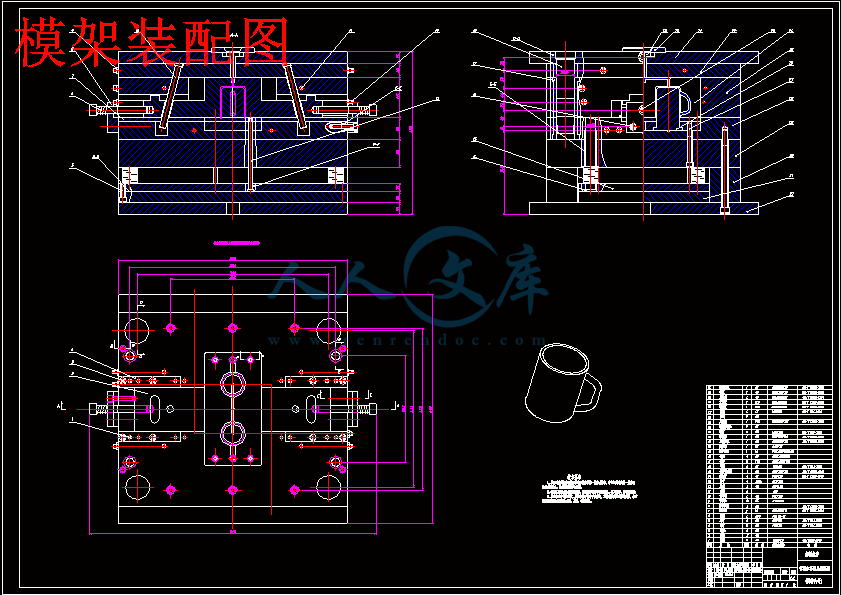
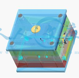
模架装配图.dwg
模架装配图.dwg

带柄水杯模具设计【带PROE三维图】【11张CAD图纸】【优秀】

收藏

资源目录
跳过导航链接。
带柄水杯模具设计【带PROE三维图】【11张CAD图纸】【优秀】.rar
模架装配图.dwg---(点击预览)
支承板.dwg---(点击预览)
推板.dwg---(点击预览)
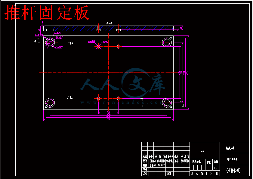
推杆固定板.dwg---(点击预览)
推料板.dwg---(点击预览)
带柄水杯模具设计说明书.doc---(点击预览)
带柄水杯模具设计开题报告.doc---(点击预览)
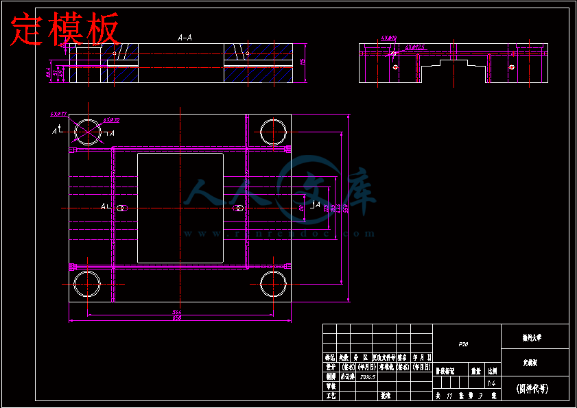
定模板.dwg---(点击预览)
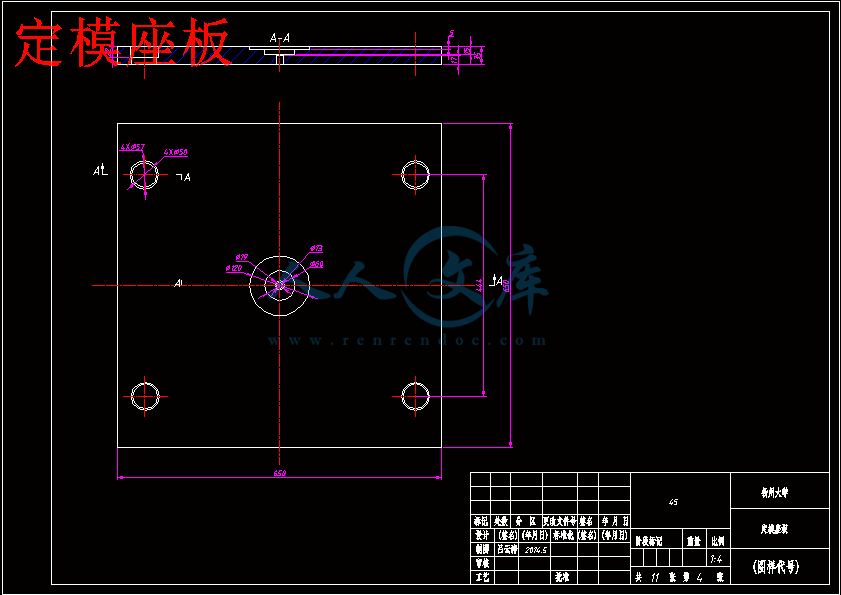
定模座板.dwg---(点击预览)
外文翻译--环保意识的设计和制造.doc---(点击预览)
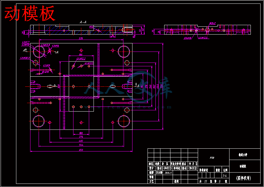
动模板.dwg---(点击预览)
动模座板.dwg---(点击预览)
前期材料.doc---(点击预览)
凹模.dwg---(点击预览)
凸模.dwg---(点击预览)
任务书.doc---(点击预览)
PROE三维建模
02.prt.1
04.prt.1
06.prt.1
07.prt.1
08.prt.1
a1_format.frm (2).1
a1_format.frm.1
a4_format.frm (2).1
a4_format.frm.1
config.win.1
gongjian.prt.1
mold_a_plate1.drw.2
mold_a_plate1.prt.13
mold_bush01.prt.1
mold_bush02.prt.1
mold_bush_sh03.prt.2
mold_b_plate1.drw.2
mold_b_plate1.prt.12
mold_connector07.prt.1
mold_connector14.prt.1
mold_connector24.prt.1
mold_connector27.prt.1
mold_dowelpin05.prt.1
mold_ejbpl_mh1.drw.2
mold_ejbpl_mh1.prt.3
mold_ejepl_mh1.drw.2
mold_ejepl_mh1.prt.4
mold_epincyl000.prt.2
mold_epincyl200.prt.1
mold_epincyl201.prt.1
mold_housing_1.drw.2
mold_housing_1.prt.3
mold_housing_1.prt.4
mold_intpl_mh_1.drw.2
mold_intpl_mh_1.prt.5
mold_loc_fh6.prt.2
mold_nipple01.prt.1
mold_nipple25.prt.1
mold_pillar_sh04.prt.1
mold_pillar_sh04.prt.2
mold_pipeplug21.prt.1
mold_pipeplug36.prt.1
mold_risers_mh1.drw.2
mold_risers_mh1.prt.3
mold_screw02.prt.1
mold_screw03.prt.1
mold_screw05.prt.2
mold_screw05.prt.3
mold_screw10.prt.1
mold_screw11.prt.2
mold_screw12.prt.1
mold_screw13.prt.1
mold_screw14.prt.1
mold_screw15.prt.1
mold_slider_asm01.asm.5
mold_sprbush5.prt.2
mold_spring_r01.prt.1
mold_strpl_fh2.drw.2
mold_strpl_fh2.prt.12
mold_s_guide01.prt.1
mold_s_lgibl01.prt.5
mold_s_lgibr01.prt.5
mold_s_lock01.prt.3
mold_s_pillar01.prt.1
mold_s_plate101.prt.2
mold_s_slider01.prt.3
mold_topclplate1.drw.2
mold_topclplate1.prt.10
mold_vol_2.prt.2
mold_vol_4.prt.2
mold_vol_6.prt.5
mold_vol_7.prt.5
mold_vol_8.prt.5
new.asm (2).1
new.asm.1
new.drw (2).1
new.drw.1
new.rep (2).1
new.rep.1
part_format.frm.1
slb (2).acc
slb.acc
slb.asm.1
slb.mfg.1
slb.prt.3
slb1m2j.acc
slb1m2j.asm.7
slb1m2j.mfg.3
slb1m2jgj.prt.2
slb1m2jmoldbase.asm.29
slb1m2jmoldbase.drw.1
slb1m2jmoldbase.rep.1
slb1m2jzhipian.prt.6
slb1m2j_ref.prt.2
slb_ref.prt.1
slb_ref_1.prt.1
tanhuan.prt.1
tjb.prt.1
tjb.prt.2
xwdk.prt.1
xwdk.prt.2
yxmb1m2j.acc
zm.prt.1
压缩包内文档预览:
预览图
编号:294160    类型:共享资源    大小:21.73MB    格式:RAR    上传时间:2014-06-29 上传人:上*** IP属地:江苏
50
积分
关 键 词:
带柄水杯 模具设计 proe三维 cad图纸
资源描述:

带柄水杯模具设计

40页 20000字数+说明书+任务书+开题报告+外文翻译+11张CAD图纸【详情如下】

PROE三维建模

任务书.doc

凸模.dwg

凹模.dwg

前期材料.doc

动模座板.dwg

动模板.dwg

外文翻译--环保意识的设计和制造.doc

定模座板.dwg

定模板.dwg

带柄水杯模具设计开题报告.doc

带柄水杯模具设计说明书.doc

推料板.dwg

推杆固定板.dwg

推板.dwg

支承板.dwg

模架装配图.dwg

摘 要

   模具是工业的重要工艺装备,是许多工业产品生产中不可缺少的组成部分。塑料作为现代社会经济发展的基础材料之一,是农业、工业、能源、交通运输等经济领域不可缺少的重要材料,其用途已渗透到经济和生活的各个领域,和钢铁、木材、水泥成为材料领域的四大支柱。模具是工业生产的基础工艺装备,被各行业广泛用于生产最终产品,其产生的价值往往是模具自身价值的几十倍、上百倍,被誉为“效益放大器”。

   本设计为带柄水杯模具制作设计,它系统的介绍了带柄水杯模具中的各个零部件的加工工艺过程及整套模具的装配和使用。其中,涉及到注射机各种参数的选取、零部件的加工方法、注射模的结构及相关的计算问题及特种加工工艺。在该模具设计中,利用CAD绘制了零件图和装配图。

   本设计在保证加工质量的前提下,尽量做到在提高生产率的同时把生产成本降到最低。

   关键词: 模具; 注射机;  塑料。

Abstract

   The mould is an important technical?equipment industry,?is an indispensable partin the production of?many industrial?products.?Plastic?as one of the?modern?social and economic development of the?basic materials,?is an important material foragricultural,?industrial,?energy,?transportation and other?areas of the economyindispensable,?its use?has?penetrated into all fields of?economic and social life,and the iron and steel,?wood,?cement has become?the four pillar?materials field.Mold?is the foundation?of industrial production technology and equipment,?the industry was widely?used in the production of?the final product,?its?value?is oftenseveral times?the value of the mold itself,?a hundred times,?known as the?"benefitamplifier".

   The design for the?shank?cup mould?design,?it?introduced the system of?assemblyand?machining process?of each parts of?shank?cup?in the mold?and?die package.The?injection machine,?relates to?the selection of various parameters,?parts of the processing?method,?the structure of the injection mould?and the relatedcomputational problems and?special processing technology.?In?the design,?to draw the part?drawing and assembly?drawing with CAD.

   This design in?the premise of ensuring the processing quality,?as far as possible to?minimize the cost of production?while improving the productivity.

   Keywords:?mould;injection machine;?plastic.  

目    录

摘要

Abstract

第一章 绪论1

1.1模具及模具工业的发展与现状1

1.2塑料成型模具的种类2

1.3注射模具的发展方向2

第二章  塑料成型工艺4

2.1 塑件材料的选择4

2.2确定成型方法4

2.3注塑成型工艺过程4

2.3.1 成型前的准备4

2.3.2 注塑成型过程4

2.3.3、塑件的后处理6

2.4塑件的结构工艺性6

2.5 塑件成型工艺参数7

2.5.1 温度7

2.5.2 压力8

2.5.3 成型周期9

第三章 带柄水杯注射模具设计10

3.1注塑成型设备10

3.1.1注塑机结构组成10

3.1.2 注塑机的分类10

3.1.3 注塑机的型号规格10

3.2注射模具分类及典型结构11

3.2.1注射模分类11

3.2.2注射模典型结构11

3.3带柄水杯模具的结构设计14

3.3.1分型面位置的确定14

3.3.2型腔数量的确定14

3.3.3 浇注系统设计15

3.3.4 成型零件设计16

3.3.5 合模导向机构设计17

3.3.6 推出机构设计18

3.3.7 模具温度调节系统设计20

3.3.8 标准模架的选用20

3.3.9 模架的尺寸计算21

3.4 注射模具与注射机的关系22

3.4.1最大注射量的校核22

3.4.2注射压力的校核22

3.4.3锁模力的校核23

3.4.4开模行程的校核23

第四章 带柄水杯模具三维设计25

4.1带柄水杯三维造型及模具设计25

4.2 模架设计27

4.2.1 定义模具模架27

4.2.2 添加设备28

4.2.3 设计顶出机构29

4.2.4 设计冷却系统29

第五章 带柄水杯注射仿真分析31

5.1 Pro/e塑料顾问的简介31

5.2 塑料顾问模块的进入31

5.3 分析功能应用31

5.4 分析结果31

5.5分析结果的输出33

5.6 注射仿真分析的优缺点33

第六章 小结与展望34

6.1小结34

6.2展望34

致 谢35

参考文献36

附  录37

   1.1模具及模具工业的发展与现状

   整体来看,中国塑料模具无论是在数量上,还是在质量、技术和能力等方面都有了很大进步,但与国民经济发展的需求、世界先进水平相比,差距仍很大。一些大型、精密、复杂、长寿命的中高档塑料模具每年仍需大量进口。在总量供不应求的同时,一些低档塑料模具却供过于求,市场竞争激烈,还有一些技术含量不太高的中档塑料模具也有供过于求的趋势。

   加入WTO,给塑料模具产业带来了巨大的挑战,同时带来更多的机会。由于中国塑料模具以中低档产品为主,产品价格优势明显,有些甚至只有国外产品价格的1/5~1/3,加入WTO后,国外同类产品对国内冲击不大,而中国中低档模具的出口量则加大;在高精模具方面,加入WTO前本来就主要依靠进口,加入WTO后,不仅为高精尖产品的进口带来了更多的便利,同时还促使更多外资来中国建厂,带来国外先进的模具技术和管理经验,对培养中国的专业模具人才起到了推动作用。

   虽然近几年模具出口增幅大于进口增幅,但所增加的绝对量仍是进口大于出口,致使模具外贸逆差逐年增大。这一状况在2006年已得到改善,逆差略有减少。模具外贸逆差增大主要有两方面原因:一是国民经济持续高速发展,特别是汽车产业的高速发展带来了对模具旺盛需求,有些高档模具国内的确生产不了,只好进口;但也确实有一些模具国内可以生产,也在进口。这与中国现行的关税政策及项目审批制度有关。二是对模具出口鼓励不够。现在模具与其它机电产品一样,出口退税率只有13%,而未达17%。

   从市场情况来看,塑料模具生产企业应重点发展那些技术含量高的大型、精密、复杂、长寿命模具,并大力开发国际市场,发展出口模具。随着中国塑料工业,特别是工程塑料的高速发展,可以预见,中国塑料模具的发展速度仍将继续高于模具工业的整体发展速度,未来几年年增长率仍将保持20%左右的水平。

   1.2塑料成型模具的种类

   1. 注射模

   注射模又称注塑模。塑料注射成型是在金属压铸成型的基础上发展起来的,成型所使用的设备是注射机。注射模通常适合于热塑性塑料的成型,目前部分热固性塑料也可以采用该方法。塑料注射成型是塑料成型生产中自动化程度最高、采用最广泛的一种成型方法。

   2. 压缩模

   压缩模又称压塑模或压胶模。塑料压缩成型是塑件成型方法中较早采用的一种方法。成型所使用的设备是塑料成型压力机,是热固性塑料通常采用的成型方法之一。与塑料注射成型相比,压缩模成型周期较长,生产效率较低。

   3. 压注模

   压注模又称传递模。压注成型所使用的设备和塑料的适应性与压缩成型完全相同,只是模具的结构不同。

   4. 挤出模

    挤出模是安装在挤出机料筒端部进行生产的,因此也称为挤出机头。成型所使用的设备是塑料挤出机。只有热塑性塑料才能采用挤出成型。

   5. 气动成型模

   气动成型模是指利用气体作为动力介质成型塑料制件的模具。气动成型包括中空吹塑成型、抽真空成型和压缩空气成型等。与其他模具相比较,气动成型模具结构最为简单,只有热塑性塑料才能采用气动成型。

   除了上述介绍的几种常用的塑料成型模具外,还有浇铸成型模、泡沫塑料成型模、聚四氟乙烯冷压成型模和滚塑模等。

   1.3注射模具的发展方向

   1.开发新的塑料成型工艺和快速经济模具。以适应多品种、少批量的生产方式。

   2.研究和应用模具的高速测量技术与逆向工程。采用三坐标测量仪或三坐标扫描仪实现逆向工程是塑料模CAD/CAM的关键技术之一。研究和应用多样、调整、廉价的检测设备是实现逆向工程的必要前提。

   3.推广应用热流道技术、气辅注射成型技术和高压注射成型技术。采用热流道技术的模具可提高制件的生产率和质量,并能大幅度节省塑料制件的原材料和节约能源,所以广泛应用这项技术是塑料模具的一大变革。制订热流道元器件的国家标准,积极生产价廉高质量的元器件,是发展热流道模具的关键。气体辅助注射成型可在保证产品质量的前提下,大幅度降低成本。目前在汽车和家电行业中正逐步推广使用。气体辅助注射成型比传统的普通注射工艺有更多的工艺参数需要确定和控制,而且其常用于较复杂的大型制品,模具设计和控制的难度较大,因此,开发气体辅助成型流动分析软件,显得十分重要。另一方面为了确保塑料件精度,继续研究发展高压注射成型工艺与模具以及注射压缩成型工艺与模具也非常重要。

   4.应用优质模具材料和先进的表面处理技术对于提高模具寿命和质量显得十分必要。

   因此,放眼未来,模具技术的发展趋势主要是模具产品向着更大型、更精密、更复杂及更经济的方向发展,模具产品的技术含量不断提高,模具制造周期不断缩短,模具生产朝着信息化、无图化、精细化、自动化的方向发展,模具企业向着技术集成化、设备精良化、产批品牌化、管理信息化、经营国际化的方向发展。

      第二章  塑料成型工艺

2.1 塑件材料的选择

   考虑到水杯的工作环境及作用来看,聚碳酸脂(PC)具有工作环境所需的性能。 PC属于热塑性塑料。(热塑性塑料—在特定的温度范围内能反复加热软化和冷却硬化的塑料。)PC的性能: 综合性能较好,无毒,化学稳定性好,耐水、油等;吸水性较小,透光率很高,介电性能良好。PC的用途: 适于制作传递中、小负荷的零部件;因PC无毒无味,可以制造医疗器械,小型日常用品等;因透光率较高,可制造大型灯罩、门窗玻璃等等透明制品。PC是非结晶型的线型结构的高聚物为此确定使用材料为:聚碳酸脂:PC

2.2确定成型方法

   塑料的种类很多,其成型的方法也很多,有注射成型、压缩成型、压注成型、挤出成型、气动与液压成型、泡沫塑料的成型等,其中前四种方法最为常用。其中,注射成型所用模具称为注射成型模具,简称注射模。注射模主要应用于成型热塑性塑料,因此根据对零件的分析,该PC材料的塑料水杯用注射成型为最佳

2.3注塑成型工艺过程

   2.3.1成型前的准备

   为使注塑成型过程顺利进行和保证塑件质量,成型前应该对所用塑料原料和设备作好一些准备工作。

   (1)检验塑料原料的色泽、颗粒大小、均匀性等;测定塑料的工艺性能;如果来料是粉料,则有时还需要对其进行染色和造粒;对易吸湿的塑料进行充分的干燥和预热。

   (2)对料筒进行清洗或拆换。

   (3)塑件带有金属嵌件时,应对嵌件进行预热,防止嵌件周围产生过大内应力。

   (4)脱模困难的塑件,要选择合适的脱模剂。脱模剂是使塑料制件容易从模具中脱出而覆在模具表面的一种助剂。常用的脱模剂有硬脂酸锌、液体石蜡、硅油等

   2.3.2注塑成型过程

   注塑过程如图2-1,首先将准备好的塑料加入注塑机的料斗,然后送进加热的料筒中,经过加热熔融塑化成粘流态塑料,在注塑机的柱塞或螺杆的高压推动下经喷嘴压入模具型腔,塑料充满型腔后,需要保压一定时间,使塑件在型腔中冷却、硬化、定型,压力撤消后开模,并利用注塑机的顶出机构使塑件脱模,最后取出塑件。这样就完成了一次注塑成型工作循环,以后是不断重复上述周期的生产过程。由上面的说明可以知道,注塑成型过程包括加料、塑化、注射、脱模等几个步骤。

   塑化是颗粒状塑料在注射机料筒中经过加热达到粘流状态并且具有良好可塑性的过程。对塑料的塑化要求是:塑料熔体在进入型腔之前,既要达到规定的成型温度,并要在规定的时间内提供足够量的熔融塑化料各处的温度尽量均匀一致,不发生或极少发生热分解以确保生产的顺利进行。螺杆式注塑机对塑料的塑化比柱塞式注塑机好得多。不管是何种形式的注塑机,注射过程均可分为充模、保压、倒流、浇口冻结后的冷却四个阶段。

   充模阶段是从柱塞或螺杆开始向前移动起,到塑料熔体经过喷嘴及模具浇注系统充满型腔时为止。

   塑料熔体充满型腔后,熔体开始冷却收缩,但柱塞或螺杆继续保持施压状态,料筒内的熔料会向模具型腔内继续流入进行补缩,以形成形状完整而致密的塑件。这一阶段称为保压阶段。    

   倒流阶段是柱塞或螺杆开始后退保压结束时开始的,这时型腔内的压力比流道内的高,因此会发生塑料熔体的倒流,从而使型腔内的压力迅速下降,直到浇口处熔料冻结倒流才结束。如果保压结束之前浇口已经

   冻结或者在喷嘴中装有止逆阀,则倒流阶段就不会存在。

   浇口冻结后的冷却是从浇口的塑料完全冻结时开始,这一阶段型腔内塑料继续进行冷却,没有塑料从浇口处流进或流出,但型腔内还可能有少量的流动。应该指出,塑料从注入型腔后即被冷却,直至脱模时为止。

   脱模是塑件冷却到一定温度后开模,在推出机构的作用下将塑料制件推出模外的过程。


   2.3.3塑件的后处理

   (1)退火处理  退火处理是将塑料制件放在定温的加热液体介质中(如热水、热的矿物油、甘油、乙二醇和液体石蜡)或热空气循环烘箱中静置一段时间,然后缓慢冷却的过程。目的是减少或消除塑件的内应力。

   (2)调湿处理  调湿处理是将刚脱模的塑件放在热水中隔绝空气进行防止氧化的退火,同时加快达到吸湿平衡的一种后处理方法。目的是使塑件的颜色、性能、尺寸得到稳定。聚酰胺类塑料制件通常需要进行调湿处理。

   2.4塑件的结构工艺性

    要想获得合格的塑料制件,除合理选用塑件的原材料外,还必须考虑塑件的结

   工艺要求,才能设计出合理的模具结构,以防止成型时产生气泡、缩孔、凹陷及开裂等缺陷,达到提高生产率和降低成本的目的。塑件结构工艺性设计的主要内容包括:尺寸和精度、表面粗糙度、塑件形状、壁厚、斜度、加强筋、支承面、圆角、

   1、壁厚

   塑料制品的壁厚对制品质量有至关重要的影响。壁厚过后,不但用料多,成本高还容易产生气泡、缩化、凹陷等缺陷,而且冷却时间长生产效率低(对热塑性塑料制品而言)。壁厚过薄,成型困难,流动阻力大,尤其是大型制品和形状复杂制品。

   制品最小壁厚的确定原则:(1)脱模时受顶出零件的推力不变形;(2)能承受装配时紧固力。

   壁厚因制品大小和塑料品种的不同而异。热塑性塑料制品的最小壁厚可达到0.25mm,但一般在(0.6~0.9)mm之间。常用壁厚为(2~4)mm。塑料水杯就取壁厚为3mm

   2、制品的精度

影响制品精度的因素较多。首先是模具的制造精度和模具的磨损量,其次是成型工艺条件的变化所引起的塑料收缩率的波动。另外,成型后的实效率变化和模具结构形式对尺寸精度也有一定的影响。因此,对塑料制品的精度要求不能过高,应在保证使用性能的情况下,尽可能选用低精度等级。

   3、制品的表面粗糙度

   塑料制品的表面粗糙度主要取决于成型模具型腔表面的粗糙度。另外,塑料品种,成型工艺以及成型模具型腔表面的磨损和腐蚀对制品的表面粗糙度也有一定的影响。一般情况下,模具型腔表面的粗糙度也有一定的影响。一般情况下,模具型腔表面的粗糙度要比所成型制品的表面粗糙度低1-2级。

   本课题可选用Ra(3.2~0.2)μm

   2.5 塑件成型工艺参数

   2.5.1温度

   在注塑成型时需控制的温度有料筒温度、喷嘴温度、模具温度等。

   (1)料筒温度  料筒温度应控制在塑料的粘流温度Tf(对结晶型塑料为熔点Tm)和热分解温度Td之间。

   料筒温度直接影响到塑料熔体充模过程和塑件的质量。料筒温度高,有利于注射压力向模具型腔内传递,另外,使熔体粘度降低,提高流动性,从而改善成型性能,提高生产率,降低制品表面粗糙度。但料筒温度过高,时间过长时,塑料的热降解量增大,塑件的质量会受到很大影响。选择料筒温度时,应考虑以下几方面的影响因素:

   ① 塑料的特性  热敏性塑料如聚甲醛、聚氯乙烯等要严格控制料筒的最高温度和在料筒中的停留时间;玻璃纤维增强的热塑性塑料由于流动性差而要适当提高料筒温度;对于热固性塑料,为防止熔体在料筒内发生早期硬化,料筒温度倾向于取小值。

   ② 注塑机类型  螺杆式注塑机由于螺杆转动时的剪切作用能获得较大的摩擦热,促进塑料的塑化,因而料筒温度选择比柱塞式注塑机低10~20℃。

   ③ 塑件及模具结构特点  薄壁塑件的型腔比较狭窄,塑料熔体注入时的阻力大,冷却快。料筒温度应选择高一些,反之则低一些。对于形状复杂或带有嵌件的制件,或者熔体充模流程曲折较多或较长时,料筒温度也应选择高一些。

   料筒温度并不是一个恒温,而是从料斗一侧开始到喷嘴为止是逐步升高的,这样可使塑料温度平稳上升达到均匀塑化的目的。

   (2)喷嘴温度  选择喷嘴温度时,考虑到塑料熔体与喷孔之间的摩擦热能使熔体经过喷嘴后出现很高的温升,为防止熔体在直通式喷嘴可能发生的“流涎现象”,通常喷嘴温度略低于料筒的最高温度。但对于热固性塑料一般都将喷嘴温度的取值高于料筒温度,这样一方面使其自身具有良好的流动性,另一方面又能接近硬化温度的临界值,即保证了注射成型,又有利于硬化定型。

   料筒温度和喷嘴温度主要影响塑料的塑化和流动,由于其影响因素很多,一般都在成型前通过“对空注射法”或“塑件的直观分析法”来进行调整,以便从中确定最佳的料筒和喷嘴温度。

   (3)模具温度  模具温度主要影响塑料在型腔内的流动和冷却,它的高低决定于塑料的结晶性、塑件的尺寸与结构、性能要求以及其他工艺条件(熔料温度、注射压力及注射速度、成型周期等)。如对于熔体粘度高的非结晶型塑料应采用较高的模温;塑件壁厚大时模温一般要高,以减小内应力和防止塑件出现凹陷等缺陷。对于热固性塑料模具温度一般较高,通常控制在150~220 ℃度范围,另外动模温度有时还需要比定模高出10~15 ℃,这样会更有利于塑件硬化定型。

   模具温度根据不同塑料的成型条件,通过模具的冷却(或加热)系统控制。

   对于要求模具温度较低的塑料,如聚乙烯、聚苯乙烯、聚丙烯、ABS塑料、聚氯乙烯等应在模具上设冷却装置;对模具温度要求较高的塑料,如聚碳酸脂、聚砜、聚甲醛、聚苯醚等应在模具上设加热系统。

   2.5.2压力

   注塑成型过程中的压力包括塑化压力和注射压力两种。

   (1)塑化压力 塑化压力又称背压,是注塑机螺杆顶部熔体在螺杆转动后退时受到的压力。一般操作中,塑化压力应在保证塑件质量的前提下越低越好,具体数值随所选用的塑料品种而变化,通常很少超过6 MPa。但要注意的是,背压力如果过小,物料易充入空气,使计量不准确,塑化不均匀。

   (2)注射压力  注射压力是指柱塞或螺杆头部注射时对塑料熔体所施加的压力。它的作用:一是克服塑料熔体从料筒流向型腔时的阻力,保证一定的充模速率;二是对塑料熔体进行压实。注射压力的大小,取决于塑料品种、注射机类型、模具浇注系统的结构、尺寸与表面粗糙度、模具温度、塑件的壁厚及流程大小等多种因素。确定注射压力的原则是:

   ① 对于热塑性塑料,注射压力一般在40~130 MPa之间。熔体粘度高,冷却速度快的塑料以及成型薄壁和长流程的塑件,采用高压注射有利于充满型腔;成型玻璃纤维增强塑料时采用高压注射有利于塑件表面光洁。其他均应选用低压慢速注射为宜。但要提醒的是,如果注射压力过高,塑件易产生飞边使脱模困难,另外使塑件产生较大的内应力,甚至成为废品。注射压力过低则易产生物料充不满型腔,甚至根本不能成型等现象。

   ② 对于热固性塑料,由于熔料中填料较多,粘度较大,且在注射过程中对熔体有温升要求,注射压力一般要选择大一些,常用范围约为100~170 MPa。

   ③ 在其他条件相同的情况下,柱塞式注塑机作用的注塑压力应比螺杆式的大,因为塑料在柱塞式注塑机料筒内的压力损失比螺杆式的大。

   2.5.5时间(成型周期)

   完成一次注塑过程所需的时间称为注塑成型周期。它包括以下几部分:

   (1)注射时间  注射时间包括充模时间、保压时间和合模冷却时间。其中保压时间和冷却时间合计为总的冷却时间。充模时间直接反比于充模速率,生产中约为3~5 s。保压时间就是对塑料的压实时间,在整个注射时间中所占比例较大,约为20~120 s。冷却时间以保证塑件脱模时不引起变形为原则,一般约为30~120 s。生产中注射时间一般在0.5~2min,厚大件可达5~10 min。

   (2)其他时间(辅助时间)包括开模、脱模、涂脱模剂、安放嵌件、合模等时间。第六章 小结与展望

   6.1小结

   在本次毕业设计中,我感觉到毕业设计不只是对以前所学知识的检验,更是对自己能力的一种提高。下面我对整个毕业设计做一下总结。

   第一是选题,选题是毕业设计的开端,本次设计我选择了带柄水杯模具设计。第二是收集资料,完成毕业设计的前期工作材料。第三是使用Pro/E完成模具,模架的设计以及使用CAD软件完成相关的零件图和装配图。第四是撰写毕业设计说明书。

   在这个过程我懂了许多东西,也培养了我独立工作的能力。

   6.2展望

   通过本次毕业设计,我感到自己应用基础知识及专业知识解决问题的能力得到了大大地提高。我想,我到工作单位后,将能够更快的适应工作岗位和工作要求。我对自己充满信心。参考文献

   [1]模具设计与制造技术教育丛书编委会编.模具结构设计. 机械工业出版社. 2006 年7月

   [2] 李翔鹏 康顺利主编.《Pro/ENGINEER Wildfire3.0 模具设计》.中国铁道出版社 .2006年12月

   [3]陈志刚主编.《塑料模具设计》[M].北京机械工业出版社 .2002年7月

   [4] 吴兆祥主编.《模具材料及表面处理》[M].北京机械工业出版社 .2003年11月

   [5] 肖爱明 王芸主编.《Pro/ENGINEER Wildfire模具设计》.兵器工业出版社.2005年6月

   [6]郭晓俊 孙江宏主编.《Pro/ENGINEER Wildfire3.0中文版模具设计》.清华大学出版社.2007年12月

   [7]塑料模设计手册编写组.《塑料模设计手册》.北京机械工业出版社 1982年

   [8]姜勇主编.《AutoCAD2006基础培训教程》.人民邮电出版社.2006年3月

   [9] 伍先明等编著.《塑料模具设计指导》[M].国防工业出版社 .2006年5月

   [10] 邹强主编.《塑料模具设计参考资料汇编》[M].清华大学出版社.2005年

   [11]邹玉堂编著.《Pro/ENGINEER实用教程》[M].机械工业出版社.2005年

   [12] 杨占尧 自柳主编.《塑料模具典型结构设计实例》.化工公业出版社.2008年9月

   [13]申开智主编.《塑料成型模具(第二版)》 .中国轻工业出版社.2009年5月

   [14]丁  浩主编.《 塑料加工基础》.上海科技出版社 .1998年7月

   [15]李秦蕊主编.《塑料模具设计》.西安工业大学出版社 .1997年3月

   [16]张玉平主编.《Pro/ENGINEER Wildfire4.0中文版模具设计》.电子工业出版社2008年5月

   [17]?赵蓓蓓.?初探塑料模具材料现状及发展方向[J].?2009年4月

   [18]?孙安垣?我国改性塑料行业的发展前景[M].《工程塑料应用》.2010年11月

   [19]?伍先明 王群.?塑料模具设计指导[M].??国防工业出版社?2006年4月

   [20]?朱光力 ?万金保.?塑料模具设计[M].??清华大学出版社 2003年6月

内容简介:
扬州大学广陵学院毕业设计(论文)任务书系 部: 专 业: 机械设计制造及其自动化 学生姓名: 吕云涛 学号: 100007124 毕业(论文)题目: 带柄水杯模具设计 起 迄 日 期: 2014-02-17 2014-06-01 设计(论文)地点: 指 导 老 师: 高 征 兵 专 业 负 责 人: 发任务书日期: 2014 年 2 月17 日毕业设计(论文)任务书1、本毕业设计(论文)课题应达到的目的:(1)熟悉塑料模具的理论知识(2)了解塑料模具的设计方法(3)运用Pro/E软件设计塑料零件的上下模(4)撰写毕业设计说明书2、本毕业设计(论文)课题任务的内容和要求(包括原始数据、技术要求、工作要求等):(1)内容:1 设计塑料件成型模型2 模具三维造型3 绘制模具零件图、装配图4 撰写毕业设计说明书(2) 要求:1 充分阅读文献,搜集相关资料2 在了解塑料加工工艺的基础上,应用Pro_E软件设计塑料件成型模具3 完成模具装配图、凹模、凸模、垫板的零件的三维工程图3、对本毕业设计(论文)课题成果的要求(包括毕业设计论文、图表、实物样品等):(1)带柄水杯上、下模;(2)注射模装配图; (3)注射模主要零件的零件图;(4)注塑模模架设计;(5)注射模设计说明书;4、主要参考文献:(1)范崇洛主编 机械加工工艺学 东南大学出版社 2009年 (2)胡兆国主编 机械加工基础 西南交大出版社、 2007年(3)傅水根主编 机械制造工艺学基础 清华大学出版社 2011年(4)冯辛安主编 机械制造装备设计 机械工业出版设 2004年(5)黄虹主编. 塑料成型加工与模具.北京:化学工业出版社.2002 (6)王善勤主编 .塑料注射成型工艺与设备.北京:中国轻工出版社.2000.3 (7)屈华昌 塑料成型工艺与模具设计.北京:机械工业出版社1996.4 (8)何忠保等编 .典型零件模具图册.北京:机械工业出版社.2000.11 (9)钱可强 机械制图.北京:高等教育出版社.2003.6 (10)廖念钊,古莹庵等.互换性与技术测量.北京:中国计量出版社.2000.1 (11)伍先明,王群等.塑料模具设计指导书.国防工业出版社.2008.2 (12)廖月莹,何冰强主编.塑料模具设计指导与资料汇编.大连理工大学出版社.2007.8 (13)冯新爱主编.塑料模具工程师手册.北京:机械工业出版社.2009.1 (14)何忠保等编.典型零件模具图册.北京:机械工业出版社2007.8(15)陈淑岭.插座注射模设计.模具制造2008年第3期 毕业设计(论文)任务书5、本毕业设计(论文)课题工作进度计划起止日期工 作 内 容第13周了解相关知识、完成实习调研,作开题报告第4、5周完成模具结构设计,包括凸凹模具、模架的三维造型第6、7周完成相关的零件图、装配图。中期检查第810周撰写毕业设计说明书第11、12周完善相关资料、答辩所在专业审核意见:负责人: 年 月 日学院意见:院长:年 月 日 扬州大学广陵学院毕业设计(论文)前期工作材料学生姓名: 吕云涛 学号: 100007124 系 部: 专 业: 机械设计制造及其自动化 设计(论文)题目: 带柄水杯模具设计 指导老师: 高 征 兵 材 料 目 录序号名 称数量备注1毕业设计(论文)选题、审题表12毕业设计(论文)任务书13毕业设计(论文)实习调研报告14毕业设计(论文)开题报告(含文献综述)15毕业设计(论文)外文资料翻译(含原文)16毕业设计(论文)中期检查表1 2014年 2 月 17 日注:毕业设计(论文)中期检查工作结束后,请将该封面与目录中各材料合订成册,并统一存放在“毕业设计(论文)资料袋中(打印件一律用A4纸型)。扬州大学广陵学院毕业设计选题、审题表学 院广陵学院选 题教 师姓名高征兵专 业机械设计制造及其自动化专业技术职务讲师申报课题名称 课题性质课题来源ABCD课题简介了解注塑模具,对模具的结构认识,使用现代CAD、CAM技术设计 模具。设计(论文)要 求(包括应具备的条件)1、实习报告2、毕业设计(论文)开题报告3、外文翻译4、设计塑料模具三维造型、模具型腔、模架 5、毕业设计(论文)说明书课题预计工作量大小大适中小课题预计难易程度难一般易所在专业审定意见:负责人(签名):年 月 日院主管领导意见: 签名: 年 月 日说明:1、该表作为本科学生毕业设计(论文)课题申报时专用,由选题教师填写,经所在专业有关人员讨论,负责人签名后生效;2、有关内容的填写见背面的填表说明,并在表中相应栏打“”课题一旦被学生选定,此表须放在“毕业设计(论文)资料袋”中存档。实习报告终于等到了实习的时候了,很早以前就从老师和学姐学长那里打听到了有毕业实习,那时候可以说是急切地期盼着这一天的到来,因为大家再也无法满足于课堂教学,尽管从同学朋友那里了解到实习并非像想象中的那样是一件快乐的事情。在实习期间虽然很累、很苦,但我却感到很快乐!因为我们在学到了作为一名机制专业学生所必备的知识的同时还锻炼了自己的动手能力。而且也让我更深刻地体会到伟大的诗人李白那一名言:只要功夫深,铁杵磨成针的真正内涵! 在刚刚到达实习单位的时候,我的心情是既兴奋又激动同时还有点担心,兴奋激动是因为我看到了成摞的零件图、装配图、电路图等等,这是在学校见不到的,可以说我们在学校见到的图和这些图比起来简直就是小巫见大巫。当然,刚才说了,我的心中同时还有些担心,担心是因为我的师傅是什么样的人呢?让我干什么呢?我能干得好么?我要是干得不好会怎么样呢?一系列的问号一直不停的我的脑子中浮现着。于是,我推开了我要去的办公室的门,我的毕业实习之路也就此开始!一、实习过程在我推开办公室门的同时,我看到了我的师傅,我的实习老师。我万万没想到的是,我的老师居然是个女的。我一直都认为,搞机械的一般都会是男的,而且是那种上岁数的老师傅,没想到我的师傅是个四十来岁女的,顿时我的压力就少了很多。刚到了单位,老师带着我们这些实习生在单位到处逛了逛,哪里有什么,哪里是什么,都给我们认真讲解。同时也跟我们说了很多生活上的事情,比如说工作时间,午休时间等等,一点都没有老师的架子,就像是家里人,家里的长辈一样,很亲切。在我们都熟悉了解了我们的实习单位之后,老师对我们进行了分组同时分配了个人的任务。当老师分配了工作岗位之后,我很幸运的被分到了院材料室,从事零件测绘以及文件的收集整理工作。自认为自己的机械制图学的还不错,本来以为会很简单,没想到跟自己想象的很不一样。在学校的时候,作为一名机械设计专业的一名学生,掌握机械的制图与测绘的必要性可想而知。 测绘实训是我们机械设计专业的一个重要实践环节,学校也根据专业情况学校开设了很多的测绘的实训课,上课期间我坚持听从老师的安排,按计划完成每天的实训任务,从中也更加深刻的了解机械的设计,制造与研发 ,认真的完成好每一次实训,为学好更深层次的专业知识打好基础。然而在实际的工作岗位中,跟学校的学的还是不太一样。当我看到桌子上的很多零件图,测绘图的时候,还是很傻眼。因为图纸都很大很大,在学校我见过最大的图纸是A0的,我们平时也很少会用到A0的图纸,但是,实习单位的图纸基本上都是A0的图纸,甚至还有更大的。当然不仅仅是机械制图的图纸,也有很多是电路图,线路图等等,让我顿时就就得很凌乱,都不知道应该干什么好。估计这时候老师有看出来了我的疑惑,给我讲解之后给我安排了我的工作任务:1、结合在学校学到的知识,了解测绘的一般方法和步骤,掌握测绘技能及绘图能力,并为后以后的工作扎下初步基础;2、通过零件草图,装配图和零件工作的绘制,培养自己实际动手能力和零部件测绘能力。使自己能恰当选择表达方案、合理布图,正确绘图,并在老师指导下完成尺寸标注及各项技术要求注写;3、了解简单机器的装配工艺。通过全面、系统的零部件测绘训练,培养自身初步的工程设计能力;4、熟悉运用有关资料(如国家标准,规范及规定画法等)。初步培养查阅标准资料的能力;5、培养自己团结协作的工作作风和严谨的学习态度,增强责任感。看到了自己的工作任务,我也就开始我的工作了。在开始测绘之前,我看了看办公室书架上面的书,基本上都是关于机械的东西,机械制图,机械原理等等,同时还有很多关于机械设计各项参数的书,也有很多是关于国家标准的书。看完了书之后又看了看桌子上已经画好的图发现,很多的手绘图基本上都是草图很少有表表准准的零件图或者装配图。我们在学校的时候,基本上都是用手画装配图或者零件图啊。后来问了老师才知道,原来现在的很多单位都是用手画出草图,标出相应的尺寸,装配方式等相关参数,最后用电脑绘画出标准的零件图装配图等等。而且像我们在学校使用的测绘软件是Auto-CAD、PRO-ENGINEER这两个软件,我在单位用的也是这个软件,因为我知道怎么用Auto-CAD以及PRO-ENGINEER绘图,然而老师告诉我现在单位用电脑绘图很少使用Auto-CAD、PRO-ENGINEER,大多用的都是SOLIDWORK、UG、CAXA等等。作为一名机械专业的学生,我不光要进行测绘也要去院车间进行实习,于是在实习最后几天的时候,老师带着我来到了院车间,学习铣工。我在车间实习的第一天看了关于铣工实习的有关的知识与我铣工实习过程中的注意事项的碟片。看到那飞转的机器、飞溅的铁花,令我既担心又激动。担心的是,如果那飞转的机器隆隆声让人心惊肉跳和那鲜红的铁花四处飞溅的发出耀眼的的光芒令人眼花缭乱激动的是,我终于可以亲自动手操作了,我想每一个工科的学生都想一试身手吧!其实,对我们这些工科的学生来说这是一次理论与实习相结合的绝好机会,又将全面地检验我们知识水平。铣工实习是机械类各专业学生必修的实习性很强的技术基础课。学生在铣工实习过程中通过独立地实习操作,将有关机械制造的基本工艺知识、基本工艺方法和基本工艺实习等有机结合起来的,进行工程实习综合能力的训练及进行思想品德和素质的培养与锻练。其实,现在的工厂加工车间都是大批量生产加工零件,换句话说,很多的地方人工铣或者说是手工铣逐渐被数控铣所代替,所以编程也就越来越重要了。也就是在这个时候,我发现我自己要学的还有很多,单凭借学校学的知识肯本不够用,要是想让自己更优秀只能用知识武装自己了。二、经验总结时光转瞬即逝,两个月的实习时间转眼就过去了,我想我在这段时间里学到了很多也懂得了很多。通过现场实习、观察,我知识面扩大了。实习使我们获得了基本生产的感性知识,同时又锻炼和培养了我们大学生吃苦耐劳的精神,也我们接触社会、了解机械行业状况、了解就业行情的一个重要途径,逐步实现由学生到社会的转变,并且让我们初步了解企业管理的基本方法和技能;体验企业工作的内容和方法。这些实际知识,对我们学习后面的课程乃至以后的工作,都是十分必要的基础。在实习期间也知道了学校和单位的差别,学校是学习的地方,而单位则是工作的地方,任何单位都是以获利为主,如果说我们的设计成本昂贵或者不容易生产,任何单位都是不会生产的。当然,我们同时也学到单位各位老师、各位师傅的敬业、严谨精神。老师们不耐其烦地帮我们查找工作中的错误,一遍又一遍。可能有的错误对于老师来讲十分的幼稚,但是老师还是能够认真的讲解,直到我们真正搞清楚弄明白为止,因此在这里我要再次感谢我的实习老师陈宏,她的谆谆教诲让我至今年难以忘记,我会拿她当作标尺,在今后的生活和工作中严格要求自己。 扬州大学广陵学院毕业设计中期检查表学生姓名 学号 指导教师高征兵选题情况课题名称 难易程度偏难适中偏易工 作 量较大合理较小符合规范化的要求任务书有无开题报告有无外文翻译质量优良中差学习态度出勤情况好一般差工作进度快按计划进行慢中期工作汇报及解答问题情况优良中差中期成绩评定:所在专业意见: 负责人 年 月 日8第二篇译文环保意识的设计和制造ECDM研究的问题包括:产品与过程集成与材料选择系统的设计,评估消费者的需求和产品使用的集成模型的发展,处理或回收,改进的方法,工具和对环境危害和成本或效益的风险评估程序,在加工或最终产品的材料,降低对环境的影响替代,在预测特定的政府法规的影响在整个产品生命周期技术的进步,新的或改进的制造过程,和增加的寿命,可以减少环境影响制造新的散装材料和涂料的研制1 能源,材料和资源的关注关于在ECDM方法和技术的发展,在过去的十年里有了巨大的增长的研究。国家制造科学中心创造了一个对抗程序来识别和解决重大环境问题(例如,提高生活质量,帮助合作解决环境问题,工业和环境安全的替代品取代过时的和有害的程序)。使用两种方法来减少生产过程的环境影响:消除或减少有害物质的使用过程,并分析不同替代生产过程的废物的产生机制。在第一种方法中,大多数的研究主要集中在材料替代选择,而第二种方法试图改善制造过程的安全化学分离。在设计过程中,材料的选择可以帮助回收过程。好的材料和制造工艺的选择可以提高技术效率和生产力,以及减少对环境的影响。选择最合适的材料和工艺的任务由于几个原因非常复杂:1)在材料和工艺的可用数量快速增长;2)增加新的规格,数量应满足,包括经济和环境法规的限制;3)材料短缺,这需要一个搜索一个兼容的替代。博克提供材料和工艺的选择方法,使用一个交互式的专家系统,称为营(计算机辅助材料工艺的选择)。营设计者提供了一个工具选择的材料和工艺组合。该系统,使用查询和内置的规则,对一个设计师的逻辑选择一个特定的材料和工艺组合。Whitmer 2,奥尔森,萨瑟兰开发的两两比较的方法确定的设计时应注重什么部分,影响产品的需求决定的。这种方法提供了一个层次决定生产环保意识的产品,和样品进行了比较。这些决定包括:1)对零件材料的选择;2)数和紧固件使用的类型;3)接触的零件的润滑油;4)部分在一个组件之间的几何关系。从比较的结果被用来确定的设计工作,最大限度地提高相对于环境设计的有效性分布。2 回收拆卸模型在ECDM文学,许多研究人员强调循环结束(EOL)产品的重要性和产品拆卸回收的有效作用。循环是由jovane等人的定义。“回收材料或部件的产品使他们获得新的产品。”另一个定义是由班克罗夫特为“产品设计以促进产品和物料回收利用。“这些定义中的“闭合回路”的材料和组件重用他们在产品生命周期不同阶段的原材料或辅助材料使用后。(1)循环狼和艾伦说,造纸行业将作为其输出的50%倍之多。然而,在塑料工业中,只有一小部分被回收。狼和爱伦还报道说,有58000000000磅的塑料树脂在美国售出的小于1%的回收。石井,尤邦克斯,他提出了一个用于回收废旧产品产品退役模型设计。作者用“丛的概念,“这是一个集组件和组件共享一个共同的特点,根据设计者的意图。一个无形的效益回收所产生的是“绿色”的形象。回收废旧产品的其他重大利益会导致整个部件或组件的重用。例如,电子材料(如硅,锗,镓,铟)可以获利的回收,因为他们的高生产成本。许多工业过程已经提出了从电子元件提取这些有价值的元素。回收要求的材料,并在丛的紧固方法与现有技术兼容。综述了各种金属henstack回收为基础的项目实践,侧重于废钢的汽车。研究产生的回收设计的一般性原则,包括简化机械拆卸,避免自我污染的材料组合,规范使用的材料,从钢项目分离铜含量高的项目。与回收设计相关的两个工程问题拆解技术和回收成本。西蒙指出,拆除所需的知识的组成部件的目的地或拆卸回收的可能性。然而,从一个产品是为了达到其生命的结束时间,技术将在循环再造的先进。这种现象揭示EOL产品的回收困难。西蒙提出了解决该问题的两个原则:1)去除最有价值的部分的第一和2)最大化“屈服”每个拆解操作。维腾堡提出的一个部件和材料的循环路径的概念,设想的宝马。它需要一个“瀑布模型”降低价值,其中注意力首先集中在拆卸零件适合重用具有最高的价值。电子废物的法令和二手车迫使制造商回收废法令,重复使用可回收的馏分,和处理残渣。在汽车行业,宝马是回收和拆卸设计的领导者。Z1模型与一个塑料的皮肤,可以从金属底盘20分钟一二个座位的汽车。门,保险杠,前,后,侧面板是由可回收的热塑性塑料采用GE。的宝马3251也使用可回收的塑料配件及目标市场环境意识的客户。通过这些努力,宝马已确定一些指引,使拆卸和回收容易。材料识别是回收的另一个有趣的方法。它需要一个能够识别材料技术,包括使用的比例和填充材料类型。理想的情况下,该技术应该是廉价的,手持使用不同的部件,和用于在一个车间式环境显著持久。一些研究人员已经在这方面的工作取得了不同程度的成功。舍戈尔德表明,傅里叶变换红外光谱的基础设备,虎和鸟是善于识别塑料和一些填充材料。这是不可能的或经济的回收产品完全;因此,回收利用的目的是最大限度地利用资源的质量和剩余产品的潜力,减少污染。扎斯曼,Kriwet,和Seliger提出三个目标应该设计评估中考虑:1)利润最大化(效益)在一个产品的寿命;2)使用的零件数量最大化;和3)的量最小化(重量)的垃圾废物。(2)拆卸人们已经认识到,使用过的产品的拆卸是必要使循环经济可行的处理技术现状。3安全和健康问题另一个ECDM是安全和健康问题。在汽车、电子等行业,最常见的焊料的今天是由铅和锡(37%的铅和63%的锡)。然而,由于铅的极端毒性,它已被限制或禁止住宅油漆,汽油,和许多其他产品在过去的十年。因此,大量的研究集中在替代锡铅焊料与无铅或导电胶。 第二篇英文原文Environmentally Conscious Design and Manufacturing The research issues in ECD&M include: integration of product and process design with material selection systems,development of models for assessing the integration of consumer demand and product use,disposal or recycling,improvement in methods,tools and procedures for evaluation of the risks associated with environmental hazards and the cost or benefit,substitution of materials with lower environmental impact in processing or in the final product,advancement in techniques for forecasting the effects of specific governmental regulations over the complete product life cycle,new or improved manufacturing processes,and development of new bulk materials and coatings with increased life spans that can be manufactured with decreased environmental impact. 1.Energy,Materials,and Resource Concern Research concerning the development of methods and techniques in ECD&M has grown tremendously in the past decade.The National Center for Manufacturing Sciences created an ECM program to identify and solve major environmental problems(for example,to improve the quality of life,to help the industry collaboratively solving the environmental problem,and to replace obsolete and harmful procedures with environmentally safe alternatives). Two approaches are used to reduce the environmental impact of manufacturing processes: eliminate or reduce the use of hazardous substances in the processes,and analyze the mechanisms of waste generation in different alternative manufacturing processes.In the first approach,most research focuses on the material substitution and selection,while the second approach attempts to improve the safety of manufacturing process.Material selection during the design process for chemical separation can be an aid to the recycling process.Good material and manufacturing process selection can improve technical efficiency and productivity,as well as reduce the environmental impact.The task of selecting the most suitable material and process has become very complex due to several reasons:1) rapid growth in the number of materials and processes available;2) increase in the number of new specifications to be satisfied,including economic and environmental regulatory constraints;and 3) materials shortages,which require a search for a compatible substitution. Bock provided a material and process selection methodology using an interactive expert system, called CAMPS(Computer-Aided Material Process Selection).CAMPS provide the designer with a tool for selecting the material and process combination.This system,using queries and built-in rules,simulates a designers logic in choosing a particular material and process combination. Whitmer 2, Olson, and Sutherland developed the Pairwise Comparison Approach to determine what portion of the design time should be focused on decisions that affect the demand of products. This approach provides a hierarchy of decisions for producing an environmentally conscious product,and sample comparisons were made. These decisions include: 1)material selection for parts; 2)number and type of fasteners used; 3)lubricant used for parts in contact;and 4)geometrical relationship among parts within an assembly.Results from the comparisons are used to determine the distribution of the design effort that maximizes the effectiveness of the design with respect to the environment. 2.Recycling and Disassembly Modeling In the ECD&M literature,many researchers emphasize the importance of recycling end-of-life (EOL) products and the role of product disassembly for effective recycling. Recycling is defined by Jovane et al.asrecovering materials or components of a used product to make them available for new products. Another definition was given by Bancroft as the use of product design to facilitate the recovery and reuse of materials in the product. These definitions infer closing the loop of materials and components after usage by reusing them for raw materials or secondary materials at different stages of the products life cycle. (1) Recycling. Wolf and Ellen reported that the paper industry recycles as much as 50% of its output. However, in the plastics industry, only a small portion is recycled. Wolf and Ellen also reported that there were 58 billion pounds of plastic resin sold in the United States and less than 1% of this was recycled. Ishii, Eubanks, and Marco proposed a design for a product retirement model for recycling EOL products. The authors used the concept of clump, which is a collection of components and subassembly that share a common characteristic based on the designers intent. One intangible benefit arising from recycling is the green image. The other significant benefit of recycling EOL products would result from reusing whole parts or subassemblies. For example, electronic materials (such as gallium, germanium, silicon, and indium) can be profitably recycled because of their high production cost. Many industrial processes have been proposed for extracting these valuable elements from electronic components. Recycling requires that materials and fastening methods in the clump are compatible with existing technologies. Henstack reviewed recycling practices for various metal-based items, which focuses on steel scrap in automobiles. The study has generated some general principles of design for recyclability, including simplifying mechanical disassembly, avoiding self-contaminating combinations of materials, standardizing materials used, and separating high copper content items from steel items. Two engineering problems associated with design for recyclability are dismantling techniques and recycling costs. Simon pointed out that dismantling required the knowledge of the destination or recycling possibility of the component parts disassembled. However, from the time a product is designed to the time it reaches the end of its life, techniques will have advanced in recycling and reengineering. This phenomenon reveals the difficulties of recycling EOL products. Simon suggested two guidelines for dealing with this problem: 1)remove the most valuable parts first and 2) maximize the yield of each dismantling operation. Wittenburg proposed the concept of a recycling path of components and materials, as envisaged by BMW. It entails a cascade model of decreasing values, in which attention is first focused on the disassembled parts suitable for reuse that have the highest value. The Decree on Electronic Waste and the Decree on Used Cars forced manufacturers to reclaim waste, to reuse the recyclable fraction, and to dispose of the residue. In the automobile industry, BMW is the leader in design for recycling and disassembly. The Z1 model is a two-seat automobile with an all-plastic skin that can be removed from the metal chassis in 20 minutes. The doors, bumpers, and front, rear, and side panels are made of recyclable thermoplastics produced by GE. The BMW 3251 also uses recyclable plastic parts and target-markets to environmental conscious customers. Through these efforts, BMW has identified some guidelines that make disassembly and recycling easier. Material recognition is another interesting approach of recycling. It requires a technology capable of identifying materials, including the proportion and type of filler materials used. Ideally, the technology should be cheap, hand-held for use on different components,and significantly durable for use in a workshop-type environment. A number of researchers have been working in this area with varying success. Shergold indicated that the Fourier Transform Infrared-based equipment that Rover and Bird developed is good at identifying plastics and some filler materials. It is not possible or economical to recycle a product completely; therefore, the aim of recycling is to maximize the recycle resources and to minimize the mass and pollution potential of the remaining products. Zussman, Kriwet, and Seliger proposed three objectives that should be considered during the design evaluation: 1) maximization of profit (benefits-costs) over a products lifespan; 2) maximization of the number of parts reused; and 3) minimization of the amount (weight) of landfill waste. (2) Disassembly. It has been recognized that disassembly of used products is necessary to make recycling economically viable in the current state of the art of reprocessing technology. Disassembly is defined by Brennan, Gupta, and Taleb as the process of systematic removal of desirable constitute parts from an assembly while ensuring that there is no impairment of the parts due to the process. There are both economic and environmental sound reasons for disassembly. Many issues and research need to be addressed in the area of disassembly. The most significant technical challenge is how to design a product for easy disassembly. Designing a product with easydisassembly constraints as well as easy assembly constraints is likely to be a very difficult task. In the past, products and machines were designed with only the assembly operations considered. Some of the problems to be addressed during design stages are the following: 1) Ease of separation. Design for ease of separation, handling, and cleaning of all product components. 2) Fasteners. New fasteners should be developed, and the existing ones should be replaced by other fastening methods. Taking apart a snap-fitted or pop-in, pop-out product is much easier and requires less energy than taking apart a welded product. 3) Modularity design. The importance of using assemblies in a products design is to ease dealing with a product after its useful life. 4) Material selection. The variety of material types must be minimized to increase the recyclability of the product. Highly recyclable materials such as aluminum and thermoplastics should be encouraged, while the use of thermosets, which cannot be recycled, should be minimized. Research from the CIM Institute by Rose and Evans focused on disassembly-oriented lifecycle analyses, where recyclability of the product was evaluated under possible future trends in recycling technology and economy. At the Swiss Federal Institute of Technology, an evaluation procedure has been proposed to support product design according to conflicting design for disassembly criteria. Each criterion is weighted and the final decision made taken on the basis of scaling all relevant criteria. Leonard reported that two basic methods of disassembly were used: reverse assembly and brute force. For reverse assembly, if a fastener is screwed in, then it is screwed out; if two parts are snap-fit together, then they are snapped apart. For brute force,parts are just pulled or cut. Seliger, Zussman, and Kriwet stated that some obstacles make disassembly difficult for todays manufactured product. First, it is difficult to gain all the information necessary to plan the disassembly. Parts of the product might have been modified during repair, and wear can make joined elements difficult to remove. In addition, many consumer products are not designed for ease of disassembly. Engineers have done an outstanding job of meeting functional requirements and federal emission regulations. Traditionally, the engineers concentrated on improving productivity and made the product easier to be assembled. Fastening processes, such as welding and adhesive bonding, are permanent-type systems. However, engineers will now have to incorporate recyclability and disassembly into their designs when creating future products. Disassembly sequence is another problem encountered in the design for disassembly. The problems associated with the disassembly sequence are 1) freeing the part of all attachments; 2) finding the succeeding part in the disassembly sequence; and 3) disassembly of the succeeding part. 3.Safety and Health Issues Another area with ECD&M is safety and health issues. Within the automotive and electronic industries, the most common solder being used today is composed of lead and tin (37% Pb and 63% Sn). However, because of leads extreme toxicity, it has been restricted or banned from residential paints, gasoline, and numerous other products over the last decade. Therefore, much research has focused on the substitution of tin-lead solder with either non-lead or conductive adhesive.第一篇译文(中文) 2.3注射模 2.3.1注射模塑注塑主要用于热塑性制件的生产,它也是最古老的塑料成型方式之一。目前,注塑占所有塑料树脂消费的30%。典型的注塑产品主要有杯子器具、容器、机架、工具手柄、旋钮(球形捏手)、电器和通讯部件(如电话接收器),玩具和铅管制造装置。 聚合物熔体因其较高的分子质量而具有很高的粘性;它们不能像金属一样在重力流的作用下直接被倒入模具中,而是需要在高压的作用下强行注入模具中。因此当一个金属铸件的机械性能主要由模壁热传递的速率决定,这决定了最终铸件的晶粒度和纤维取向,也决定了注塑时熔体注入时的高压产生强大的剪切力是物料中分子取向的主要决定力量。由此所知,成品的机械性能主要受注射条件和在模具中的冷却条件影响。 注塑已经被应用于热塑性塑料和热固性塑料、泡沫部分,而且也已经被改良用于生产反应注塑过程,在此过程中,一个热固树脂系统的两个组成部分在模具中同时被注射填充,然后迅速聚合。然而大多数注塑被用热塑性塑料上,接下来的讨论就集中在这样的模具上。 典型的注塑周期或流程包括五个阶段(见图2-1):(1)注射或模具填充;(2)填充或压紧;(3)定型;(4)冷却;(5)零件顶出。 图2-1 注塑流程 塑料芯块(或粉末)被装入进料斗,穿过一条在注射料筒中通过旋转螺杆的作用下塑料芯块(或粉末)被向前推进的通道。螺杆的旋转迫使这些芯块在高压下对抗使它们受热融化的料筒加热壁。加热温度在265至500华氏度之间。随着压力增强,旋转螺杆被推向后压直到积累了足够的塑料能够发射。注射活塞迫使熔融塑料从料筒,通过喷嘴、浇口和流道系统,最后进入模具型腔。在注塑过程中,模具型腔被完全充满。当塑料接触冰冷的模具表面,便迅速固化形成表层。由于型芯还处于熔融状态,塑料流经型芯来完成模具的填充。典型地,在注塑过程中模具型腔被填充至95%98%。 然后模具成型过程将进行至压紧阶段。当模具型腔充满的时候,熔融的塑料便开始冷却。由于塑料冷却过程中会收缩,这增加了收缩痕、气空、尺寸不稳定性等瑕疵。为了弥补收缩,额外的塑料就要被压入型腔。型腔一旦被填充,作用于使物料熔化的压力就会阻止模具型腔中的熔融塑料由模具型腔浇口处回流。压力一直作用到模具型腔浇口固化。这个过程可以分为两步(压紧和定型),或者一步完成(定型或者第二阶段)。在压紧过程中,熔化物通过补偿收缩的保压压力来进入型腔。固化成型过程中,压力仅仅是为了阻止聚合物熔化物逆流。 固化成型阶段完成之后,冷却阶段便开始了。在这个阶段中,部件在模具中停留某一规定时间。冷却阶段的时间长短主要取决于材料特性和部件的厚度。典型地,部件的温度必须冷却到物料的喷出温度以下。 冷却部件时,机器将熔化物塑炼以供下一个周期使用。高聚物受剪切作用和电热丝的能量情况影响。一旦喷射成功,塑炼过程便停止了。这是在冷却阶段结束之前瞬间发生的。然后模具打开,部件便生产出来了。2.3.2注塑模具 注塑模具与它们的生产出来的产品一样,在设计、精密度和尺寸方面各不相同。热塑性模具的功能主要是把可塑性聚合物制成人们想要的形状,然后再将模制部件冷却。 模具主要由两个部件组成:(1)型腔和型芯,(2)固定型腔和型芯的底座。模制品的尺寸和重量限制了模具型腔的数量,同时也决定了所需设备的能力。从模具成型过程考虑,模具设计时要能安全合模、注射、脱模的作用力。此外,浇口和流道的设计必须允许有效的流动以及模具型腔均匀填充。图2-2举例说明了典型注射模具中的部件。模具主要由两部分组成:固定部分(型腔固定板),熔化的聚合物被注入的旁边;在注塑设备结尾或排出旁边的瓣合(中心板)部分。模具这两部分之间的分隔线叫做分型线。注射材料通过一条叫做浇口的中心进料通道被转运。浇口位于浇口轴套的上面,它逐渐缩小(锥形)是为了促进模具打开时浇注材料的释放。在多型腔模具中,主流道将高分子聚合熔化物提供到流道系统中,流道系统通过浇口流入每个模具型腔。 中心板支撑主型芯。主型芯的用途是确立部件的内部结构。中心板有一个支持或支撑板。支撑板反过来被背对注塑模顶杆空间的U型结构的柱子支撑,注塑模顶杆空间由背面的压板和垫块组成。被固定在中心板上的U型结构,为也被叫做脱模行程的顶出行程提供了空间。在固化的过程中,部件从主型芯周围收缩以至于当模具打开的时候,部件和浇口随着瓣合机构一起被带出来。接着,中央的起模杆被激活,引起脱模板向前移动以至于顶杆能够推动部件离开型芯。带有冷却通道的上下模被提供,冷却通道通过冷却水循环流通来吸收热塑性高分子聚合熔融物传递给模具的热量。模具型腔也包含好的通风口(对于5毫米而言,通风口应该为0.02到0.08毫米)来确保填充过程中没有空气滞留在模具型腔内。 1-顶杆 2-顶出板 3-导套 4-导柱 5-下顶针板 6-脱件销 7-复位杆 8-限位杆 9-导柱 10-导柱 11-型腔板 12-浇口套 13-塑料工件 14-型芯 现在使用的有六种基本注射模具类型。它们是:(1)双板模;(2)三板模;(3)热流道模具;(4)绝热保温流道模具;(5)温流道模具;和(6)重叠压塑模具。图2-3和图2-4阐明了这六种基本注射模具类型。 1.双板模一个双板模具由每块都带有型腔和型芯的两块平板组成。平板被固定在压板上。瓣合机构包含工件自动拆卸机构和流道系统。所有注射模具的基本设计都有这个思想。双板模具是用来制作要求大型浇口制品的最合理的工具。2. 三板模这种类型的模具由三块板组成:(1)固定板或压板被连接到固定压盘上,通常包含主流道和分流道;(2)当模具打开的时候,包含分流道和浇口中间板或型腔固定板是被允许浮动的;(3)活动板或阳模板包含模制件和用来除去模制件的顶出装置。当按压进行打开的时候,中间板和活动板一起移动,因此释放了主流道和分流道系统和清除了浇口处模制品的赘物。当模具打开的时候,这种设计类型的模具使分离流道系统和模制件变成了可能。这种模具设计让点浇口浇注系统能够运用。3. 热流道模具在这个注射模具的流程中,分流道要保持热的,目的是使熔融的塑料一直处于流动的状态。实际上,这是一个“无流道”模具流程,有时候它也被叫做无流道模具。在无流道模具中,分流道被包含在自己的板中。热流道模具除了模塑周期中模具的分流道部分不被打开这点外,其他地方与三板注射模具相似。加热流道板与剩下的冷却部分的模具是绝缘的。分流道中除了热加板,模具中剩余部分是一个标准的两板模具。无流道模具相比传统的浇口流道模具有几个优点。无流道模具没有模具副产品(浇口,分流道,主流道)被处理或者再利用,也没有浇口与制件的分离。周期仅仅要求制件被冷却和从模具中脱离。在这个系统中,从注射料筒到模具型腔,温度能够达到统一。4. 绝热保温流道模具绝热流道模具是热流道模具的一种演变。在这种类型的模具中,分流道材料的外表面充当了绝缘体来让熔融材料通过。在隔热的模具中,通过保留自己的温度使模具中的物料一直是熔化的。有时候,一个分料梭和热探测器被加入模具中来增加柔韧性。这种类型的模具对于多孔中心浇口的制件来说是理想的。5. 温流道模具它是热流道模具的一种演变。在这种模具中,流道而不是流道板被加热。这是通过电子芯片嵌入探测器实现的。6. 重叠压塑模具重叠压塑注射模具顾名思义。一个多重两板模具其中的一块板被放在另一块板的上面。这种结构也可以用在三板模具和热流道模具上。两板重叠结构使单一的挤压输出量加倍,与一个型腔数量相同的两板模具相比,还减少了一半的合模压力。这种方式也被叫做“双层模塑”。2.3.3压膜机1. 传统的注塑机在这个流程中,塑料颗粒或粉末被倒入一个机器料斗中,然后被送入加热料筒室。一个活塞压缩物料,迫使物料渐进地通过加热料筒中物料被分料梭慢慢散开的加热区域。分料梭被安装在料筒的中心,目的是加速塑料体中心的加热。分料梭也有可能被加热,以便塑料能够内外一起被加热。物料从加热料斗流经喷嘴进入模具。喷嘴是料斗和模具之间的密封装置它被用来阻止因为剩余压力而引起的物料泄露。模具在注塑机的末端被夹具夹紧闭合。对于聚苯乙烯而言,机器末端两三吨的压力通常用在之间和流道系统中每个小的投影面积上。传统的活塞式机器是唯一能生产斑点部分的类型的机器。另一种类型的注塑机将塑料材料充分地混合,以至于仅有一种颜色被生产出来。2. 柱塞式预塑机这种机器使用了分料梭活塞加热器来预塑塑料颗粒。塑料颗粒变成熔化状态之后,液态的塑料被倒入一个蓄料室,直到塑料准备好被压入模具。这种类型的机器比传统的机器生产零件的速度更快,因为在制件冷却的时间中,模具腔被填满进行喷射。由于注射活塞在流动的物料中工作,因此在压缩颗粒的时候没有压力损失。这种现象能够应用在带有更多投影面积的大型制件上。柱塞式预塑机的其他特点与传统的单一活塞式注塑机是一样的。图2-5举例说明了柱塞式预塑机。 3. 螺杆式预塑机在这种注塑机中,用挤压机来塑化塑料物料。旋转的螺杆使塑料芯块向前,提供给挤压机料筒的加热内壁。熔融的,塑化的物料从挤压机移动到一个蓄料室,然后通过注射活塞移动到模具中。螺杆的应用有以下优势:(1)便于物料更好的混合及塑料溶化后的剪切作用;(2)流动物料硬度的范围更广及热敏材料可以流动;(3)能在更短的时间内进行色泽改变;(4)模具制件中的应力更小4. 往复式螺杆注塑机这种类型的注塑机使用了一个水平的挤压机来代替加热室。螺杆的旋转使塑料物料向前移动通过挤压机料筒。随着物料流经带螺杆的加热料筒,物料从颗粒状态变为塑料熔融状态。螺杆往复的过程中,传递给模制物料的热量是由螺杆和挤压机的料筒壁之间的摩擦和传导引起的。当物料向前移动的时候,螺杆返回到在挤压机料筒前方决定物料容量的行程开关处。在这个时候,与典型挤压机类似的挤压过程结束了。当物料注射到模具中,螺杆向前移动来转移料筒中的物料。在这个注塑机中,螺杆既充当活塞,又充当螺杆。模具中的浇口截面冻结阻止回流之后,螺杆开始旋转并且向后移动,进行下一个周期。图2-5展示了往复式螺杆注塑机。这种形式的注塑有几个优点。它更有效地塑化热敏感材料,由于螺杆的混合作用更快地混合色泽。给材料加热的文都能够更低,并且整个周期时间可以更短。第一篇英文原文 2.3 Injection Molds 2.3.1 Injection Molding Injection molding is principally used for the production of thermoplastic parts, and it is also one of the oldest. Currently injection-molding accounts for 30% of all plastics resin consumption. Typical injection-molded products are cups, containers, housings, tool handles, knobs, electrical and communication components (such as telephone receivers), toys, and plumbing fittings. Polymer melts have very high viscosities due to their high molecular weights; they cannot be poured directly into a mold under gravity flow as metals can, but must be forced into the mold under high pressure. Therefore while the mechanical properties of a metal casting are predominantly determined by the rate of heat transfer from the mold walls, which determines the grain size and grain orientation in the final casting, in injection molding the high pressure during the injection of the melt produces shear forces that are the primary cause of the final molecular orientation in the material. The mechanical properties of the finished product are therefore affected by both the injection conditions and the cooling conditions within the mold. Injection molding has been applied to thermoplastics and thermosets, foamed parts, and has been modified to yield the reaction injection molding (RIM) process, in which the two components of a thermosetting resin system are simultaneously injected and polymerize rapidly within the mold. Most injection molding is however performed on thermoplastics, and the discussion that follows concentrates on such moldings. A typical injection molding cycle or sequence consists of five phases (see Fig. 2-1): (1) Injection or mold filling; (2) Packing or compression; (3) Holding; (4) Cooling; (5) Part ejection. Fig. 2-1 Injection molding process Plastic pellets (or powder) are loaded into the feed hopper and through an opening in the injection cylinder where they are carried forward by the rotating screw. The rotation of the screw forces the pellets under high pressure against the heated walls of the cylinder causing them to melt. Heating temperatures range from 265 to 500 F. As the pressure builds up, the rotating screw is forced backward until enough plastic has accumulated to make the shot. The injection ram (or screw) forces molten plastic from the barrel, through the nozzle, sprue and runner system, and finally into the mold cavities. During injection, the mold cavity is filled volumetrically. When the plastic contacts the cold mold surfaces, it solidifies (freezes) rapidly to produce the skin layer. Since the core remains in the molten state, plastic flows through the core to complete mold filling. Typically, the cavity is filled to 95%98% during injection. Then the molding process is switched over to the packing phase. Even as the cavity is filled, the molten plastic begins to cool. Since the cooling plastic contracts or shrinks, it gives rise to defects such as sink marks, voids, and dimensional instabilities. To compensate for shrinkage, addition plastic is forced into the cavity. Once the cavity is packed, pressure applied to the melt prevents molten plastic inside the cavity from back flowing out through the gate. The pressure must be applied until the gate solidifies. The process can be divided into two steps (packing and holding) or may be encompassed in one step (holding or second stage). During packing, melt forced into the cavity by the packing pressure compensates for shrinkage. With holding, the pressure merely prevents back flow of the polymer melt. After the holding stage is completed, the cooling phase starts. During cooling, the part is held in the mold for specified period. The duration of the cooling phase depends primarily on the material properties and the part thickness. Typically, the part temperature must cool below the materials ejection temperature. While cooling the part, the machine plasticates melt for the next cycle. The polymer is subjected to shearing action as well as the condition of the energy from the heater bands. Once the shot is made, plastication ceases. This should occur immediately before the end of the cooling phase. Then the mold opens and the part is ejected. 2.3.2 Injection Molds Molds for injection molding are as varied in design, degree of complexity, and size as are the parts produced from them. The functions of a mold for thermoplastics are basically to impart the desired shape to the plasticized polymer and then to cool the molded part. A mold is made up of two sets of components: (1) the cavities and cores, and (2) the base in which the cavities and cores are mounted. The size and weight of the molded parts limit the number of cavities in the mold and also determine the equipment capacity required. From consideration of the molding process, a mold has to be designed to safely absorb the forces of clamping, injection, and ejection. Also, the design of the gates and runners must allow for efficient flow and uniform filling of the mold cavities. Fig.2-2 illustrates the parts in a typical injection mold. The mold basically consists of two parts: a stationary half (cavity plate), on the side where molten polymer is injected, and a moving half (core plate) on the closing or ejector side of the injection molding equipment. The separating line between the two mold halves is called the parting line. The injected material is transferred through a central feed channel, called the sprue. The sprue is located on the sprue bushing and is tapered to facilitate release of the sprue material from the mold during mold opening. In multicavity molds, the sprue feeds the polymer melt to a runner system, which leads into each mold cavity through a gate. The core plate holds the main core. The purpose of the main core is to establish the inside configuration of the part. The core plate has a backup or support plate. The support plate in turn is supported by pillars against the U-shaped structure known as the ejector housing, which consists of the rear clamping plate and spacer blocks. This U-shaped structure, which is bolted to the core plate, provides the space for the ejection stroke also known as the stripper stroke. During solidification the part shrinks around the main core so that when the mold opens, part and sprue are carried along with the moving mold half. Subsequently, the central ejector is activated, causing the ejector plates to move forward so that the ejector pins can push the part off the core. Both mold halves are provided with cooling channels through which cooled water is circulated to absorb the heat delivered to the mold by the hot thermoplastic polymer melt. The mold cavities also incorporate fine vents (0.02 to 0.08 mm by 5 mm) to ensure that no air is trapped during filling. Fig. 2-2 Injection mold 1-ejector pin 2-ejector plate 3-guide bush 4-guide pillar 5-ejector base plate 6-sprue puller pin 7-push-back pin 8-limit pin 9-guide pillar 10-guide pillar 11-cavity plate 12-sprue bushing 13-plastic workpiece 14-core There are six basic types of injection molds in use today. They are: (1) two-plate mold; (2) three-plate mold, (3) hot-runner mold; (4) insulated hot-runner mold; (5) hot-manifold mold; and (6) stacked mold. Fig. 2-3 and Fig. 2-4 illustrate these six basic types of injection molds. Fig. 2-3 This illustrates three of the six basic types of injection molding dies (1) Two-plate injection mold (2) Three-plate injection mold (3) Hot-runner mold See Fig. 2-4 for the other three types. Fig. 2-4 This illustrates three of the six basic types of injection molding dies (1) Insulated runner injection mold (2) Hot manifold injection mold (3) Stacked injection mold See Fig. 2-3 for the other three types. 1. Two-Plate Mold A two-plate mold consists of two plates with the cavity and cores mounted in either plate. The plates are fastened to the press platens. The moving half of the mold usually contains the ejector mechanism and the runner system. All basic designs for injection molds have this design concept. A two-plate mold is the most logical type of tool to use for parts that require large gates. 2. Three-Plate Mold This type of mold is made up of three plates: (1) the stationary or runner plate is attached to the stationary platen, and usually contains the sprue and half of the runner; (2) the middle plate or cavity plate, which contains half of the runner and gate, is allowed to float when the mold is open; and (3) the movable plate or force plate contains the molded part and the ejector system for the removal of the molded part. When the press starts to open, the middle plate and the movable plate move together, thus releasing the sprue and runner system and degating the molded part. This type of mold design makes it possible to segregate the runner system and the part when the mold opens. The die design makes it possible to use center-pin-point gating. 3. Hot-Runner Mold In this process of injection molding, the runners are kept hot in order to keep the molten plastic in a fluid state at all times. In effect this is a runnerless molding process and is sometimes called the same. In runnerless molds, the runner is contained in a plate of its own. Hot runner molds are similar to three-plate injection molds, except that the runner section of the mold is not opened during the molding cycle. The heated runner plate is insulated from the rest of the cooled mold. Other than the heated plate for the runner, the remainder of the mold is a standard two-plate die. Runnerless molding has several advantages over conventional sprue runner-type molding. There are no molded side products (gates, runners, or sprues) to be disposed of or reused, and there is no separating of the gate from the part. The cycle time is only as long as is required for the molded part to be cooled and ejected from the mold. In this system, a uniform melt temperature can be attained from the injection cylinder to the mold cavities. 4. Insulated Hot-Runner Mold This is a variation of the hot-runner mold. In this type of molding, the outer surface of the material in the runner acts like an insulator for the melten material to pass through. In the insulated mold, the molding material remains molten by retaining its own heat. Sometimes a torpedo and a hot probe are added for more flexibility. This type of mold is ideal for multicavity center-gated parts.5. Hot-Manifold This is a variation of the hot-runner mold. In the hot-manifold die, the runner and not the runner plate is heated. This is done by using an electric-cartridge-insert probe. 6. Stacked Mold The stacked injection mold is just what the name implies. A multiple two-plate mold is placed one on top of the other. This construction can also be used with three-plate molds and hot-runner molds. A stacked two-mold construction doubles the output from a single press and reduces the clamping pressure required to one half, as compared to a mold of the same number of cavities in a two-plate mold. This method is sometimes called “two-level molding”. 2.3.3 Mold Machine 1. Conventional Injection-Molding Machine In this process, the plastic granules or pellets are poured into a machine hopper and fed into the chamber of the heating cylinder. A plunger then compresses the material, forcing it through progr
温馨提示:
1: 本站所有资源如无特殊说明,都需要本地电脑安装OFFICE2007和PDF阅读器。图纸软件为CAD,CAXA,PROE,UG,SolidWorks等.压缩文件请下载最新的WinRAR软件解压。
2: 本站的文档不包含任何第三方提供的附件图纸等,如果需要附件,请联系上传者。文件的所有权益归上传用户所有。
3.本站RAR压缩包中若带图纸,网页内容里面会有图纸预览,若没有图纸预览就没有图纸。
4. 未经权益所有人同意不得将文件中的内容挪作商业或盈利用途。
5. 人人文库网仅提供信息存储空间,仅对用户上传内容的表现方式做保护处理,对用户上传分享的文档内容本身不做任何修改或编辑,并不能对任何下载内容负责。
6. 下载文件中如有侵权或不适当内容,请与我们联系,我们立即纠正。
7. 本站不保证下载资源的准确性、安全性和完整性, 同时也不承担用户因使用这些下载资源对自己和他人造成任何形式的伤害或损失。
提示  人人文库网所有资源均是用户自行上传分享,仅供网友学习交流,未经上传用户书面授权,请勿作他用。
关于本文
本文标题:带柄水杯模具设计【带PROE三维图】【11张CAD图纸】【优秀】
链接地址:https://www.renrendoc.com/p-294160.html

官方联系方式

2:不支持迅雷下载,请使用浏览器下载   
3:不支持QQ浏览器下载,请用其他浏览器   
4:下载后的文档和图纸-无水印   
5:文档经过压缩,下载后原文更清晰   
关于我们 - 网站声明 - 网站地图 - 资源地图 - 友情链接 - 网站客服 - 联系我们

网站客服QQ:2881952447     

copyright@ 2020-2025  renrendoc.com 人人文库版权所有   联系电话:400-852-1180

备案号:蜀ICP备2022000484号-2       经营许可证: 川B2-20220663       公网安备川公网安备: 51019002004831号

本站为文档C2C交易模式,即用户上传的文档直接被用户下载,本站只是中间服务平台,本站所有文档下载所得的收益归上传人(含作者)所有。人人文库网仅提供信息存储空间,仅对用户上传内容的表现方式做保护处理,对上载内容本身不做任何修改或编辑。若文档所含内容侵犯了您的版权或隐私,请立即通知人人文库网,我们立即给予删除!