设计任务书.doc

QTZ40塔式起重机的变幅系统设计【优秀机械毕业设计】【word+50张CAD图纸全套】

收藏

压缩包内文档预览:
预览图 预览图 预览图 预览图 预览图
编号:295367    类型:共享资源    大小:3.55MB    格式:RAR    上传时间:2014-07-07 上传人:QQ14****9609 IP属地:陕西
45
积分
关 键 词:
qtz40 塔式起重机 系统 设计 优秀 优良 机械 毕业设计 word 50 cad 图纸 全套
资源描述:

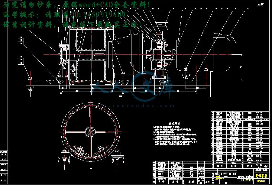
QTZ40塔式起重机总体及变幅机构的设计

QTZ40塔式起重机——变幅系统的设计

QTZ40塔式起重机的变幅系统设计【优秀机械毕业设计】【word+50张CAD图纸全套】

【带任务书+开题报告+外文翻译+实习报告】【73页@正文35260字】【详情如下】【全套设计需要咨询请加QQ1459919609】.bat

图纸总汇50张.dwg

实习报告.doc

封皮.docx

我的开题报告.doc

摘要.docx

正文.docx

目录.docx

翻译原文.pdf

英语翻译.doc

设计任务书.doc

毕业设计(论文)任务书

QTZ40塔式起重机——变幅系统的设计

1、毕业设计(论文)目的:

本次毕业设计是对机械专业学生在毕业前的一次全面训练,目的在于巩固和扩大学生在校所学的基础知识和专业知识,训练学生综合运用所学知识分析和解决问题的能力。是培养、锻炼学生独立工作能力和创新精神的最佳手段。毕业设计要求每个学生在工作过程中,要独立思考,刻苦钻研,有所创新、解决相关技术问题。通过毕业设计,使学生掌握塔式起重机的总体设计、变幅机构的设计、变幅小车的设计和计算等内容,为今后步入社会、走上工作岗位打下良好的基础。

2、毕业设计(论文)任务内容和要求(包括原始数据、技术要求、工作要求等):

(1)设计任务:

①总体参数的选择(QTZ40级别)

②结构形式

(2)总体设计

①主要技术参数性能

②设计原则

③平衡重的计算

④塔机的风力计算

⑤整机倾翻稳定性的计算

(3)变幅机构的设计和计算

①变幅机构的形式

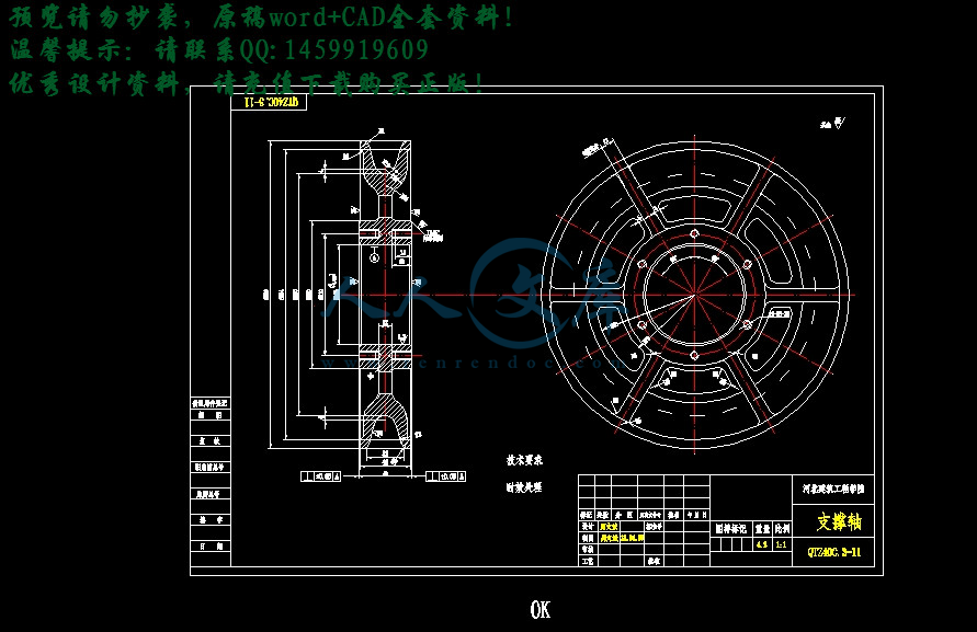
②确定卷筒尺寸

③选择电动机、减速器、制动器、联轴器

④验算实际变幅速度

⑤验算起、制动时间

⑥电动机发热验算

⑦卷筒强度的计算

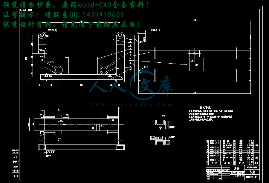
(4) 变幅小车的设计

①   变幅小车的形式

②   变幅小车的强度计算

(5) 设计要求

①  主要任务:学生应在指导教师指导下独立完成一项给定的设计任务,编写符合要求的设计说明书,并正确绘制机械与电气工程图纸,独立撰写一分毕业论文,并绘制有关图表。

②   知识要求:学生在毕业设计工作中,应综合运用多学科的理论、知识与技能,分析与解决工程问题。通过学习、钻研与实践,深化理论认识、扩展知识领域、延伸专业技能。

③   能力培养要求:学生应学会依据技术课题任务,完成资料的调研、收集、加工与整理,正确使用工具书;培养学生掌握有关工程设计的程序、方法与技术规范,提高工程设计计算、图纸绘制、编写技术文件的能力;培养学生掌握实验、测试等科学研究的基本方法;锻炼学生分析与解决工程实际问题的能力。

④   综合素质要求:通过毕业设计,学生应掌握正确的设计思想;培养学生严肃认真的科学态度和严谨求实的工作作风;在工程设计中,应能树立正确的生产观、经济观与全局观。

⑤   设计成果要求:

1)凡给定的设计内容,包括说明书、计算书、图纸等必须完整,不得有未完的部分,不应出现缺页、少图纸现象。

2)对设计的全部内容,包括设计计算、机械构造、工作原理、整机布置等,均有清晰的了解。对设计过程、计算步骤有明确的概念,能用图纸完整的表达机械结构与工艺要求,有比较熟练的认识图纸能力。对运输、安装、使用等亦有一般了解。

3)说明书、计算书内容要精练,表述要清楚,取材合理,取值合适,设计计算步骤正确,数学计算准确,各项说明要有依据,插图、表格及字迹均应工整、清楚、不得随意涂改。制图要符合机械机械制图标准,且清洁整齐。

4)对国内外塔式起重机情况有一般的了解,对各种塔式起重机有一定的分析、比较能力。

其他各项应符合本资料有关部分提出的要求。

3、毕业设计(论文)成果要求(包括图表、实物等硬件要求):

①  计算说明书一份

  内容包括:设计任务要求的选型、设计计算内容、毕业实习报告等。作到内容完整,论证充分(包括经济性论证),字迹清楚,插图和表格正规(分别进行统一编号)、批准,字数要求不少于2万字;撰写中英文摘要;提倡学生应用计算机进行设计、计算与绘图。

  ②  图纸一套

不少于四张零号图纸量

4、主要参考文献:

【1】 董刚 李建功 潘风章主编 《机械设计》(第3版) 北京:机械工业出版社 1998

【2】 张质文,虞和谦等.起重机设计手册.北京:中国铁道出版社.1997.

【3】 《机械设计手册》(第1卷)(新版)机械设计手册编委会编著 

北京:机械工业出版社 2004.8

【4】 《机械设计手册》(第2卷)(新版)机械设计手册编委会编著 

北京:机械工业出版社 2004.8

【5】 成大先主编《机械设计手册》(第4版)北京:化学工业出版社 2002

【6】 顾迪民主编《工程起重机》(第2版)北京:中国建筑工业出版社 1988

【7】 刘品主编《互换性与测量技术基础》(第2版)哈尔滨:哈尔滨工业大学出版社 2001

【8】 徐灏主编《机械设计手册》(第2版) 北京:机械工业出版社 2000

【9】 曹双寅主编《工程结构设计原理》 南京:东南大学出版社 2002

【10】刘鸿文主编《材料力学》(第4版) 高等教育出版社

【11】《QTZ400塔式起重机使用说明书》

【12】张青  张瑞军  编著《工程起重机结构与设计》北京:化学工业出版社,2008.7

【13】中华人民共和国国家标准GB/T 13752-92 《塔式起重机设计规范》 北京:中国标准出版社 1993

【14】范俊祥主编《塔式起重机》 中国建材工业出版社

【15】许镇宇、邱宣怀主编:《机械零件》 人民教育出版社

【16】刘佩衡主编《塔式起重机使用手册》  北京:机械工业出版社,2002

【17】中国建设部《钢结构设计规范》      2003.12

【18】黄靖远 龚剑霞 贾延林  《机械设计学》北京工业出版社,2002

【19】safety on construction sites  著者American Society of civil Engineers.Task Committee on Crane Safety on Constructions Sites 中图分类号:TH21-36

【20】孙在鲁 著《塔式起重机应用技术》北京:中国建材工业出版社,2003.5

【21】SAE crane standards manual 著者Backham 中图分类号:TH21-65

5、毕业设计(论文)课题工作进度计划:

起 迄 日 期工   作   内   容

2013.3.25-2013.3.28

2013.3.29-2013.4.13

2013.4.14-2013.4.20

2013.4.21-2013.5.15

2013.5.16-2013.6.5

2013.6.6-2013.6.19

2013.6.20-2013.6.21

熟悉整理资料

方案选择及总体设计

绘制总图

变幅机构、变幅小车的设计

绘制变幅机构、变幅小车装配图

绘制零件图纸

准备论文及答辩

摘要

塔式起重机作为建筑施工的主要设备,在建筑等行业发挥着极其重要的作用。塔式起重机属于臂架型起重机,由于其臂架铰接在较高的塔身上,且可回转,臂架长度较大,结构轻巧、安装拆卸运输方便,适于露天作业,因此大多数用于工业与民用建筑施工。

塔式起重机是为了满足高层建筑施工、设备安装而设计的新型起重运输机械,QTZ40塔式起重机是由建设部长沙建设机械研究院设计的新型建筑用塔式起重机,该机为水平臂架,小车变幅,上回转自升式多用途塔机。

本设计的题目是固定式QTZ40塔式起重机起升系统的设计。QTZ40塔式起重机有多种形式,此次设计的形式为上回转液压顶升自动加节,可随着建筑物的升高而升高,固定式高度为30米,在附着状态下可达到100米,其工作幅度为40米。

本设计书主要包括三部分:第一部分是QTZ40塔式起重机总体方案的选择及总体设计计算过程;第二部分是变幅机构的设计与计算:包括变幅机构的形式、确定卷筒尺寸、选择电动机、减速器、制动器、联轴器;验算实际变幅速度 验算起、制动时间;电动机发热验算;卷筒强度的计算;第三部分是变幅小车的设计:包括变幅小车的形式、变幅小车的强度计算。

关键词:QTZ40塔式起重机     总体设计:变幅系统

ABSTRACT

As an important facility, the tower crane plays an important role in construction industry. The tower crane belongs to the arm rack type crane. Its arm is hinged on the high tower body, and it may rotate. It has longer arm, dexterous structure. What’s more, it is easy to be assembled, disassembled and transported. It is suitable for the open-air work and mainly used for industry and civil construction

Tower cranes are to meet high-rise construction building, equipment installation and design as a new type machinery of lifting transport. The QTZ40 tower cranes are new tower cranes designed by Changsha Institute of the Ministry of Construction Machinery used in construction building. The aircraft is horizontal boom, trolley luffing, on the back or decanted from the tower-type multi-purpose  machines .

 The design topic is the stationary QTZ40 tower crane system and the design of lifting structure. There are many kinds of QTZ40 tower crane. The form of this design is as below. With an upper rotating hydraulic pressure propping system, the machine could add height automatically and thus rise with the building ascension. The stationary type is 30meter high; it could reach the height of 100meters when it is being adhered. Its work scope is 40 meters.

 This design book mainly includes three parts. The first part summarizes the present situation and the development tendency of the tower crane in both our country and abroad, as well as the characteristic and application occasion..The second part is the QTZ40 tower crane overall concept choice and the system design computation process; the third part is the organization design and the computation of lifting mechanism and the last is the design of the hook group.

Keywords: QTZ500 tower crane    The total design:luffing system

目录

第1章 前言1

1.1塔式起重机概述1

1.2塔式起重机的发展趋势1

第2章 总体设计2

 2.1 概述2

2.2确定总体设计方案2

2.2.1 选择确定总体参数 2

  2.2.2工作机构20

2.2.3安全保护装置28    

 2.3 总体设计设计总则30

  2.3.1 整体工作级别30

2.3.2 机构工作级别30

2.3.3 主要技术性能参数31

2.4 平衡重的计算31  

2.5 起重特性曲线33

2.6 塔机风力计算35

  2.6.1工作工况Ⅰ35

  2.6.2工作工况Ⅱ 39

2.6.3非工作工况Ⅲ41

2.7 整机的抗倾覆稳定性计算44

2.7.1工作工况Ⅰ45

  2.7.2工作工况Ⅱ 46

2.7.3非工作工况Ⅲ47

2.7.3非工作工况Ⅳ48

2.8 固定基础稳定性计算49

第3章 变幅机构的设计和计算 51

3.1变幅机构的形式 51

3.2 确定卷筒的尺寸51

  3.2.1 卷筒的名义直径51

3.2.2 多层绕卷筒相关参数计算52

3.3. 选择电动机、减速器、制动器、联轴器53

3.3.1选择电动机 53

3.3.2 选择减速器 54

3.3.3 变幅机构制动器的选择54

3.3.4变幅机构联轴器的选择 55

 3.4. 验算变幅速度57

 3.5验算起、制动时间验算 57

 3.6电动机发热校验 59

 3.7 校验卷筒强度60

第4章  变幅小车的设计61

 4.1 变幅小车的形式61

 4.2 变幅小车的设计61

    4.2.1绳索牵引式小车构造及其驱动方式61

     4.2.2 运行小车牵引力计算63

4.2.3牵引绳最大张力66      

     4.2.4 选择牵引绳67

    4.2.5 牵引卷筒计算67

毕业设计小结70

参考文献 72

第1章  前言

1.1 概述

塔式起重机是我们建筑机械的关键设备,在建筑施工中起着重要作用,我们只用了五十年时间走完了国外发达国家上百年塔机发展的路程,如今已达到发达国家九十年代末期水平并跻身于当代国际市场。

QTZ40型塔式起重机简称QTZ40型塔机,是一种结构合理,性能比较优异的产品,比较国内同规格同类型的塔机具有更多的优点,能够满足高层建筑施工的需要,可用于建筑材料和预制构件的吊运和安装,并能在市内狭窄地区和丘陵地带建筑施工。高层建筑施工中,它的幅度利用率比其他类型起重机高,其幅度利用率可达全幅度的80%。

QTZ40型塔式起重机是400kN·m上回转自升式塔机。上回转自升塔式起重机是我国目前建筑工程中使用最广泛的塔机,几乎是万能塔机。它的最大特点是可以架得很高,所以所有的高层和超高层建筑、桥梁工程、电力工程,都可以用它去完成。这种塔式起重机适应性很强,所以市场需求很大。

1.2 发展趋势

  塔式起重机是在第二次世界大战后才真正获得发展的。在六十年代,由于高层、超高层建筑的发展,广泛使用了内部爬升式和外部附着式塔式起重机。并在工作机构中采用了比较先进的技术,如可控硅调速、涡流制动器等。进入七十年代后,它的服务对象更为广泛。因此,幅度、起重量和起升高度均有了显著的提高。

就工程起重机而言,今后的发展主要表现在如下几个方面:①整机性能:由于先进技术和材料的应用,同种型号的产品,整机重量要轻20%左右;②高性能、高可靠性的配套件,选择余地大、适应性好,性能得到充分发挥;③电液比例控制系统和智能控制显示系统的推广应用;④操作更方便、舒适、安全,保护装置更加完善;⑤向吊重量大、起升高度、幅度更大的大吨位方向发展。

第2章 总体设计

2.1 概述

   总体设计是毕业设计中至关重要的一个环节,它是后续设计的基础和框架。只有在做好总体设计的前提下,才能更好的完成设计。它是对满足塔机技术参数及形式的总的构想,总体设计的成败关系到塔机的经济技术指标,直接决定了塔机设计的成败。

1.遵循“三化”:即零件标准化、产品系列化、部件通用化。

2.采用“四新”:即新技术、新结构、新材料、新工艺。

3.满足“三好”:即好制造、好使用、好维修。

制定设计总则以后,便可以编写设计任务书,在调研的基础上运用所学的知识,确定总体设计方案,保证设计的成功。

总体设计指导各个部件和各个机构的设计进行,一般由总工程师负责设计。在接受设计任务以后,应进行深入细致的调查研究,收集国内外的同类机械的有关资料,了解当前的国内外塔机的使用、生产、设计和科研的情况,并进行分析比较,制定总的设计原则。设计原则应当保证所设计的机型达到国家有关标准的同时,力求结构合理,技术先进,经济性好,工艺简单,工作可靠。

2.2 确定总体设计方案

QTZ40塔式起重机是上回转液压自升式起重机。尽管其设计型号有各种各样,但其基本结构大体相同。整台的上回转塔机主要由金属结构,工作机构,液压顶升系统,电器控制系统及安全保护装置等五大部分组成。

2.2.1 金属结构

塔式起重机金属结构部分由塔顶,吊臂,平衡臂,上、下支座,塔身,转台等主要部件组成。对于特殊的塔式起重机,由于构造上的差异,个别部件也会有所增减。金属结构是塔式起重机的骨架,承受塔机的自重载荷及工作时的各种外载荷,是塔式起重机的重要组成部分,其重量通常约占整机重量的一半以上,因此金属结构设计合理与否对减轻起重机自重,提高起重性能,节约钢材以及提高起重机的可靠性等都有重要意义。

1. 塔顶

自升塔式起重机塔身向上延伸的顶端是塔顶,又称塔帽或塔尖。其功能是承受臂架拉绳及平衡臂拉绳传来的上部载荷,并通过回转塔架、转台、承座等的结构部件或直接通过转台传递给塔身结构。

自升式塔机的塔顶有直立截锥柱式、前倾或后倾截锥柱式、人字架式及斜撑式等形式。截锥柱式塔尖实质上是一个转柱,由于构造上的一些原因,低部断面尺寸要比塔身断面尺寸为小,其主弦杆可视需要选用实心圆钢,厚壁无缝钢管或不等边角钢拼焊的矩形钢管。人字架式塔尖部件由一个平面型钢焊接桁架和两根定位系杆组成。而斜撑式塔尖则由一个平面型钢焊接桁架和两根定位系杆组成。这两种型式塔尖的共同特点是构造简单自重轻,加工容易,存放方便,拆卸运输便利。

塔顶高度与起重臂架承载能力有密切关系,一般取为臂架长度的1/7-1/10,长臂架应配用较高的塔尖。但是塔尖高度超过一定极限时,弦杆应力下降效果便不显著,过分加高塔尖高度不仅导致塔尖自重加大,而且会增加安装困难需要换用起重能力更大的辅助吊机。因此,设计时,应权衡各方面的条件选择适当的塔顶高度。

本设计采用前倾截锥柱式塔顶,断面尺寸为1.36m×1.36m。腹杆采用圆钢管。塔顶高6.115米。塔冒用无缝钢管焊接而成,顶部设有连接平衡臂拉杆和吊臂拉杆的铰销吊耳,以及穿绕起升钢丝绳的定滑轮,顶部应装有安全灯和避雷针。其结构如图2-1所示:

图2-1   塔顶结构图

2. 起重臂

1) 构造型式

塔式起重机的起重臂简称臂架或吊臂,按构造型式可分为:小车变幅水平臂架;俯仰变幅臂架,简称动臂;伸缩式小车变幅臂架;折曲式臂架。

小车变幅水平臂架,简称小车臂架,是一种承受压弯作用的水平臂架,是各式塔机广泛采用的一种吊臂。其优点是:吊臂可借助变幅小车沿臂架全长进行水平位移,并能平稳准确地进行安装就位。因此此次设计采用小车变幅水平臂架。

小车臂架可概分为三种不同型式:单吊点小车臂架,双吊点小车臂架和起重机与平衡臂架连成一体的锤头式小车臂架。单吊点小车变幅臂架是静定结构,而双吊点小车变幅臂架则是超静定结构。幅度在40m以下的小车臂架大都采用单吊点式构造;双吊点小车变幅臂架结构一般幅度都大于50m。双吊点小车变幅臂架结构自重轻,据分析与同等起重性能的单吊点小车变幅臂架相比,自重均可减轻5%-10%。小车变幅臂架拉索吊点可以设在下弦处,也可设在上弦处,现今通用小车变幅臂架多是上弦吊点,正三角形截面臂架。这种臂架的下弦杆上平面均用作小车运行轨道。

2) 分节问题

臂架型式的选定及构造细部处理取决于塔机作业特点,使用范围以及承载能力等因素,设计时,应通盘考虑作出最佳选择,首先要解决好分节问题。

小车臂架常用的标准节间长度有6、7、8、10、12m五种。为便于组合成若干不同长度的臂架,除标准节间外,一般都配设1~2个3~5m长的延接节,一个根部节,一个首部节和端头节。端头节构造应当简单轻巧,配有小车牵引绳换向滑轮、起升绳端头固定装置。此端头节长度不计入臂架总长,但可与任一标准节间配装,形成一个完整的起重臂。本次设计选用标准节长度为6m,另加上2m长的延接节。其示意图见图2-2:

图2-2臂架分节

3) 截面形式及截面尺度

塔机臂架的截面形式有三种:正三角形截面、倒三角形截面和矩形截面。小车变幅水平臂架大都采用正三角形截面,本次设计的QTZ40采用正三角形截面。选用这种方式的优点是:节省钢材,减轻重量,从而节约成本。其尺寸截面形式如图2-3所示:

图2-3  臂架截面及其腹杆布置

1-水平腹杆2-侧腹杆3-上弦杆4-下弦杆

臂架一-五节:B=1020mm H=800mm

臂架六-七节:B=1017mm H=800mm

臂架截面尺寸与臂架承载能力、臂架构造、塔顶高度及拉杆结构等因素有关。截面高度主要受最大起重量和拉杆吊点外悬臂长度影响最大。截面宽度主要与臂架全长有关。设计臂架长度为40m,共分七节。

4) 腹杆布置和杆件材料选用

矩形截面臂架的腹杆体系宜采用人字式布置方式,而三角形截面起重臂的腹杆体系既可采用人字式布置方式,也可 采用顺斜置式。此两种布置方式各有特点。

当采用顺斜置式式,焊缝长度较短、质量不易保证。焊接变形不均匀,节点刚度较差,且不便于布置小车变幅机构。因此本设计选用人字式布置方式。其优点在于,这种布置方式应用区段不受限制,焊缝长度较长,强度易于保证,焊接变形较均匀,节点刚度较好,便于布置小车变幅机构。

臂架杆件材料有多种选择可能性。一般情况下,上吊点小车变幅臂架的上弦以选用16Mn实心钢为宜,但造价要高。因此本设计选用20号无缝圆钢管。其特点是:惯性矩、长细比要小,抗失稳能力高。下弦采用等边角钢对焊的箱型截面杆件,经济实用,具有良好的抗压性能。因此上弦杆选用89×8、89×7,下弦选用的角钢型号为:75×8、75×5,臂间由销轴连接。

参考文献

【1】 董刚 李建功 潘风章主编 《机械设计》(第3版) 北京:机械工业出版社 1998

【2】 张质文,虞和谦等.起重机设计手册.北京:中国铁道出版社.1997.

【3】 《机械设计手册》(第1卷)(新版)机械设计手册编委会编著 

北京:机械工业出版社 2004.8

【4】 《机械设计手册》(第2卷)(新版)机械设计手册编委会编著 

北京:机械工业出版社 2004.8

【5】 成大先主编《机械设计手册》(第4版)北京:化学工业出版社 2002

【6】 顾迪民主编《工程起重机》(第2版)北京:中国建筑工业出版社 1988

【7】 刘品主编《互换性与测量技术基础》(第2版)哈尔滨:哈尔滨工业大学出版社 2001

【8】 徐灏主编《机械设计手册》(第2版) 北京:机械工业出版社 2000

【9】 曹双寅主编《工程结构设计原理》 南京:东南大学出版社 2002

【10】刘鸿文主编《材料力学》(第4版) 高等教育出版社

【11】《QTZ400塔式起重机使用说明书》

【12】张青  张瑞军  编著《工程起重机结构与设计》北京:化学工业出版社,2008.7

【13】中华人民共和国国家标准GB/T 13752-92 《塔式起重机设计规范》 北京:中国标准出版社 1993

【14】范俊祥主编《塔式起重机》 中国建材工业出版社

【15】许镇宇、邱宣怀主编:《机械零件》 人民教育出版社

【16】刘佩衡主编《塔式起重机使用手册》  北京:机械工业出版社,2002

【17】中国建设部《钢结构设计规范》      2003.12

【18】黄靖远 龚剑霞 贾延林  《机械设计学》北京工业出版社,2002

【19】safety on construction sites  著者American Society of civil Engineers.Task Committee on Crane Safety on Constructions Sites 中图分类号:TH21-36

【20】孙在鲁 著《塔式起重机应用技术》北京:中国建材工业出版社,2003.5

【21】SAE crane standards manual 著者Backham 中图分类号:TH21-65

内容简介:
河北建筑工程学院毕业实习报告系 别 机械工程系 专 业 机械设计制造及其自动化 班 级 机 091 班 姓 名 周文斌 学 号 2009307107 指导教师 李常胜 实习成绩 毕业实习报告1、实习目的毕业实习是大学生完成四年的全部课程之后的最重要的实践环节。也是在进行毕业设计或毕业论文时必不可少的实践性教学环节。它对于培养我们的动手能力有很大的意义,而且可以使我们了解传统的机械制造工艺和现代机械制造技术。毕业实习为大学生提供了培养和造就实践能力和创新能力的必要物质基础和良好的环境,这次毕业实习对我们毕业生来说意义非常的重大,因此每位同学都必须珍惜这一难得的机会,有效地利用宝贵的毕业实习时间,把培养实践能力和打造创新能力作为毕业实习和毕业设计的指导思想。2、实习内容老师为了我们更加感性的认识塔式起重机,安排我们去长春机械展销会参观实习。因为对塔式起重机比较陌生,所以我们对这次的实习抱很大希望,首先要对塔式起重机有个全面的了解,其次对于自己要设计的起升机构更要弄明白。我们 3 月 19 日出发,经过一天的坐火车我们来到东北老工业基地长春。第二天在老师的带领下我们观看了塔式起重机以及大型挖掘机等重要机械,让我们着实的开了眼界。各个生产商都摆放着他们的代表性产品。我们详细的看了每个部件,塔身、臂架、标准节、等等很多部件。当然我仔细看了起升机构的结构并照下了很多照片以便下来自己再细细研究。在老师的介绍下我们对塔式起重机有了初步的认识。塔式起重机是一种塔身竖立起重臂会转到起重机械。在工业与民用建筑施工中塔式起重机是完成预制构件与其他建筑材料与工具等吊装工作的主要设备。在高层建筑施工中,它的幅度利用率比其他类型起重机高。塔式起重机在高层工业和民用建筑施工的使用中一直处于领先地位。应用塔式起重机对于加快施工进度、缩短工期、降低工程造价起着重要的作用。由于塔式起重机性能参数不断完善,使建筑工艺也有可能进行许多重大改革,比如采用大型砌块、大板结构设置箱形结构后,建筑物结构件的预制装备化、工厂化达到了很高的水平。塔式起重机是在第二次世界大战后才真正获得发展的。在中国塔式起重机的生产与应用已有 40 多年的历史,经历了一个从侧回到自行设计制造的过程。经过多年的发展,中国塔式起重机行业随着全国范围建筑任务的增加而进入了一个新的兴盛时期,至此,无论从生产规模、应用范围和塔式起重机总量等角度来衡量,中国均堪称塔式起重机大国。根据国内外一些技术资料介绍,塔式起重机的发展趋势可具体归纳为吊臂长度加长、工作速度提高且能调速、改善操纵条件、更多的采用组装式结构四个方面。塔式起重机一般有四大工作机构,它们是起升机构、变幅机构、回转机构、行走机构。起升机构用来实现载荷的升降,它是塔式起重机中最重要也是最基本的机构,起升机构的性能将直接影响到整台塔式起重机的工作性能。变幅机构是塔式起重机改变工作幅度的机构,用以扩大塔式起重机的工作范围,提高工作效率。通过变幅机构能将所运输的物料运送到工作面上。回转机构是塔式起重机的主要工作机构之一,它能将起升在空间的物料绕塔式起重机垂直轴线作圆周运动,扩大塔式起重机的工作面。行走机构的作用是驱动塔式起重机沿着轨道行驶、配合其他机构完成水平运输及垂直运输工作。塔式起重机的自重和载荷重量通过行走机构的行走轮传给轨道。塔式起重机的起升机构通常由电机、制动器、减速器、卷筒、钢丝绳、滑轮组及吊钩等零部件组成。电机通过联轴器与减速器相连。减速器的输出轴上装有卷筒,它通过钢丝绳和安装在塔身或塔顶上导向滑轮及滑轮组与吊钩相连。电机工作时,卷筒将钢丝绳卷进或放出,通过滑轮组使吊钩上的物品起升或下降。当电机停止工作时,制动器通过弹簧力将制动轮刹住。塔式起重机的变幅机构按工作性质可分为非工作性变幅机构和工作性变幅机构。非工作性变幅机构指只在空载时改变幅度,调整取物装置的作业位置,而在重物装卸英东过程中幅度不再改变。这种变幅机构变幅次数少,变幅时间对起重机的生产效率影响小,一般采用较低的变幅速度,其优点是构造简单、自重轻。工作性变幅机构是指能在带载条件下变幅的机构。变幅过程是起重机工作循环主要环节,变幅时间对起重机的生产效率有直接影响,一般采用较高的变幅速度。其优点是生产率高,能更好地满足装卸工作地需要。工作性变幅机构驱动功率较大,而且要求安装限速和防止超载的安全装置,与非工作性变幅机构相比,构造复杂,自重也较大。塔式起重机的变幅机构按机构运动形式分为臂架摆动式变幅机构和运行小车式变幅机构。动臂式变幅机构式通过吊臂俯仰摆动实现变幅。小车变幅塔式起重机是指通过起重小车沿起重臂运行进行变幅的塔式起重机。综合变幅塔式起重机是指根据作业的需要臂架可以弯折的塔式起重机。塔式起重机的回转机构能使塔机的起重臂架作 360 度回转,这样就扩大了塔式起重机的工作面。塔式起重机回转机构包括回转支撑装置和驱动机构两部分。回转支撑装置为塔机的回转部分提供稳定、牢固的支撑,并将回转部分的载荷传递给塔身部分;驱动机构驱动塔机的回转部分,使其相对塔机的固定部分实现回转。塔式起重机的回转支撑装置一般有柱式回转支撑装置和滚动轴承式回转支撑装置。塔式起重机上一般采用电动回转驱动装置。回转驱动装置通常安装在塔机的回转部分上,电动机经减速器带动最后一级小齿轮,小齿轮与装在塔机固定部分上的大齿圈相啮合,以实现回转运动。行走机构用以支撑起重机本身的重量和起重载荷,并使起重机水平运行。起重机的行走方式分为有轨行走机构和无轨行走机构两类。有轨行走是指车轮在专门铺设的轨道上行走;无轨行走则采用轮胎或履带,可以在普通的道路上行驶,机动性强。通过老师的讲解使我们更深入的了解的塔式起重机的构造和功用。为我们的毕业设计做了很好的铺垫。3、实习结果实习结束了,该次实习使我们不仅掌握了有关起升机构的知识还了解了关于塔式起重机的其他部件。以前在课本上不能理解的问题都有了更深刻的认识。这次实习以及前一段时间查阅的大量资料为我的毕业设计提供了良好的基础,使我深深地体会到要想搞好设计,就必须耐心仔细地查找与设计相关的资料和信息(包括设计产品的基本功能、主要结构、应用特点及其发展前途,市场效益等) 。我国目前制造业的发展状况也粗步了解了机械制造的发展趋势。在新的世纪里,科学技术必将以更快的速度发展,更快更紧密得融合到各个领域中,而这一切都将大大拓宽机械制造业的发展方向。将来的机械制造将会向“四个化”发展,即柔性化、灵捷化、智能化、信息化。即使工艺装备与工艺路线能适用于生产各种产品的需要,能适用于迅速更换工艺、更换产品的需要,使其与环境协调的柔性,使生产推向市场的时间最短且使得企业生产制造灵活多变的灵捷化,还有使制造过程物耗,人耗大大降低,高自动化生产,追求人的智能与机器智能高度结合的智能化,以及借助于物质和能量的力量生产出价值的信息化。4、实习总结或体会毕业实习是我们从学校到社会的一座桥梁,是从理论到实际的一条纽带。加强我们综合能力的培养,使得我们既要掌握专业的基本理论和基本知识,又具有对于所学知识的运用能力以及独立工作的能力,为我们在毕业设计中、甚至为毕业后的实际工作打下了良好的基础。通过此次毕业实习我们了解到目前机械制造的发展趋势,也使我们清晰地定位我们所处的位置,对我们以后走上工作岗位起到一个良好的模范作用。纸上得来终觉浅,绝知此事要躬行。我深深地感觉到自己所学知识的肤浅和在实际运用中的专业知识的匮乏,一旦接触到实际,才发现自己知道的是多么少,这时才真正领悟到“学无止境”的含义。河 北 建 筑 工 程 学 院本 科 毕 业 设 计 ( 论 文 )题目QTZ40 塔式起重机变幅系统的设计学 科 专 业 机械设计制造及其自动化 班 级 机 091 班 姓 名 周文斌 指 导 教 师 李常胜 辅 导 教 师 河北建筑工程学院毕业设计(论文)开题报告课题名称QTZ40 塔式起重机变幅系统的设计系 别: 机械工程系 专 业: 机械设计制造及其自动化 班 级: 机 091 学生姓名: 周文斌 学 号: 2009307107 指导教师: 李常胜 课题来源 导师课题 课题类别 工程设计一、论文资料的准备1.塔式起重机概述塔式起重机是一种塔身树立起重臂回转的起重机械,简称塔机,也叫塔吊,起源于西欧。具有工作效率高、使用范围广、回转半径大、起升高度大、操作方便以及安装与拆卸比较简便等特点。主要完成在高层建筑施工中预制构件及其他建筑材料与工具等吊装工作。塔式起重机应具备下列特点:(1)起升高度和工作幅度较大、起重力矩大;(2)工作速度高,具有安装微动性能及良好的调速性能;(3)要求拆装运输方便迅速,以适应频繁转移工地的需要。2.我国塔式起重机的发展现状塔式起重机在我国的生产与应用已经有 50 余年的历史,经历了以个从测绘仿制到自行设计制造的过程,特别是进入 20 世纪 90 年代以后,我国塔式起重机行业随着全国范围建筑任务的增加而进入了一个兴盛时期,年产量连年猛增,而且有部分产品出口到国外。 现在我国的建筑用塔式起重机已越来越普遍,从普通的多层民用建筑、房地产工程、高层建筑到大型的铁路工程、桥梁工程、电力工程、水利工程等,到处都有塔机的应用。近 20 年来,市场的需求,有力的促进了技术的进步,通过研究开发、技术创新、引进消化,我们的设计手段和配套件生产能力也有了很大的进步,计算机辅助设计、微电子技术、程控语言控制技术都在塔机上得到了应用。当然也不可否认,我国的塔机产品的技术性能、制作质量和品种型号规格,与发达国家产品相比,仍然存在较大的差距,特别是基础零部件的可靠性、电气元件、液压元件、工艺安装、生产设备和检测手段等,差距更大。这就影响了我们整机产品的质量和可靠性,增加了事故隐患。对此我们绝不可以掉以轻心,要加倍努力、敢于创新、严格把关、赶超国际水平。3.我国塔式起重机的发展趋势我国大规模经济建设已有二十来年的历史,这二十来年里,大量建筑物的涌现和大型工程的兴建,铁路、公路桥梁的建设,给塔式起重机提供了良好的市场。我国的塔式起重机发展趋势可以分以下几个方面:我国塔机产品的品种、型号、规格应向多样化发展,以适应不同工程、不同用户的需求。就目前现实而言,我国塔式起重机几乎是上回转一统天下,下回转塔机很少。4. 国外发展概况 塔式起重机是在第二次世界大战后才真正获得发展的。战后各国面临着重建家园的艰巨任务,浩大的建筑工程量迫切需要大量性能良好的塔式起重机。自塔式起重机在建筑施工中显露身手并逐渐成为工程机械一个重要分支以来,已经有 50 余年历史,其间利经了曲折复杂的发展阶段。70 年代末,由于种种原因,国外塔式起重机制造业陷入了低谷,不少中小工厂纷纷停业或转产,仅少数大厂得以维持。直至 80 年代末才呈现逐渐复苏态势,1994 年为复苏年头,复苏势头最好的国家为德国。据有关资料介绍,在塔机制造业鼎盛的 70 年代,西德拥有各式塔机 48500 台,80 年代总量减至 1/3,而近几年,东西德合并,基建规模扩大,塔机产量上升,现有塔机近 40000 台,其中半数机龄不足 5 年 。如今世界塔机市场最为红火的地区为东欧和亚太(特别是东南亚) 。活跃在塔机市场上的著名产商是;德国的 Liebherr 、Peiner、 Wolff ,法国的 Potain 、BPR,意大利的 Potain-Simma、Comedil 、 Nauva 、 EDILMAC ,西班牙的 Comensa ,芬兰的 Betrox ,丹麦的 KRLL 澳大利亚的 Favco。这些大厂为了在国际塔机市场上占有更多份额,莫不注重总结经验,认真分析市场动态,下大力气进行产品的更新和开发。近年来,国外塔机在新产品开发上大致有下列一些特点: (1)更多的厂家注重开发经济型城市塔机并扩展成系列。 (2)国外塔机新产品中,有一些新颖的轻、中型折叠式快速安装塔机颇引人注目。 (3) 根据一些国家城建当局的有关规定,为防止塔机臂架在狭窄的空间运行发生矛盾,避免吊臂相互碰撞以及碰到邻近的建筑物,在城市高层建筑密集地区施工必须采用动臂式自升塔式起重机。 (4)在经过较长时间研制之后,履带式水平臂架塔机作为一种新产品正式问世。 (5) 变频调速系统在国外塔机新产品上得到推广应用。 (6)高新技术开始在塔机上应用。 (7)无论上回转或下回转式塔机,都十分重视驾驶室的平面设计和空间处理。5.QTZ40 型塔式起重机的简单介绍及其市场前景QTZ40 自升式塔吊为上回转、水平臂架、小车变幅、液压自升式多用途塔吊。起重力矩 400KN.m,最大起重量 4t,独立架设时最大起升高度可达 30 米,加附着最大起升可达 100 米,最大幅度分 40 米。该机参数先进,性能优良可靠,造型美观,质量精良,结构简单实用,设有先进的安全装置,维修方便,使用安全,价格合理,是广大中小建筑企业理想的建筑施工机械。同时该机适用性好,广泛用于中高层以下的各类工业与民用建筑和滑模施工的吊装,还常用于港口、货场的装卸。二、本课题的目的(重点及拟解决的关键问题)本毕业设计是对机械专业学生在毕业前的一次全面训练,目的在于巩固和扩大学生在校期间所学的基础知识和专业知识,训练学生综合运用所学知识分析和解决问题的能力。是培养、锻炼学生独立工作能力和创新精神之最佳手段。毕业设计要求每个学生在工作过程中,要独立思考,刻苦钻研,有所创造的分析、解决技术问题。通过毕业设计,使学生掌握装载机的总体设计、工作装置设计、牵引计算等技术工作的实现方法,为今后步入工作岗位打下良好的基础。重点及拟解决的问题是:1、变幅机构和变幅小车的形式,卷筒尺寸计算2、小车的强度计算3、整机倾翻稳定性的计算三、主要内容、研究方法、研究思路1.主要内容塔式起重机的总体设计、变幅机构的设计、变幅小车的设计和计算等内容。2. 研究方法本设计的题目是 QTZ40 变幅机构的设计,主要设计理念是通过参照同类塔式起重机进行设计。QTZ40 塔式起重机有多种形式,此次设计的形式为上回转液压顶升自动加节,固定式高度,工作幅度等设计。本机性能先进,结构合理,操作使用安全可靠其主要特点是起重力矩大、起升高度高、工作幅度大、作业空间广、使用效率高。3.研究思路本设计书主要包括三部分:第一部分是 QTZ40 塔式起重机总体方案的选择及总体设计计算过程;第二部分是变幅机构的设计与计算:包括变幅机构的形式、确定卷筒尺寸、选择电动机、减速器、制动器、联轴器;验算实际变幅速度 验算起、制动时间;电动机发热验算;卷筒强度的计算。第三部分是变幅小车的设计:包括变幅小车的形式、变幅小车的强度计算。最后,还需要对不同截面的稳定性、刚度及强度进行验算以及校核。四、总体安排和进度(包括阶段性工作内容及完成日期)2013.3.25-2013.3.28 熟悉整理资料2013.3.29-2013.4.13 方案选择及总体设计2013.4.14-2013.4.20 绘制总图2013.4.21-2013.5.15 变幅机构、变幅小车的设计2013.5.16-2013.6.5 绘制变幅机构、变幅小车装配图2013.6.6-2013.6.19 绘制零件图纸2013.6.19-2013.6.21 准备论文及答辩五、主要参考文献【1】 董刚李建功潘风章主编机械设计 (第 3 版)北京:机械工业出版社1998【2】 张质文,虞和谦等.起重机设计手册.北京:中国铁道出版社.1997.【3】 机械设计手册 (第 1 卷) (新版)机械设计手册编委会编著北京:机械工业出版社2004.8【4】 机械设计手册 (第 2 卷) (新版)机械设计手册编委会编著北京:机械工业出版社2004.8【5】 成大先主编机械设计手册 (第 4 版)北京:化学工业出版社2002【6】 顾迪民主编工程起重机 (第 2 版)北京:中国建筑工业出版社1988【7】 刘品主编互换性与测量技术基础 (第 2 版)哈尔滨:哈尔滨工业大学出版社2001【8】 徐灏主编机械设计手册 (第 2 版)北京:机械工业出版社2000【9】 曹双寅主编工程结构设计原理南京:东南大学出版社2002【10】刘鸿文主编材料力学 (第 4 版) 高等教育出版社【11】 QTZ400 塔式起重机使用说明书【12】张青 张瑞军 编著工程起重机结构与设计北京:化学工业出版社,2008.7【13】中华人民共和国国家标准 GB/T13752-92塔式起重机设计规范北京:中国标准出版社1993【14】范俊祥主编塔式起重机 中国建材工业出版社【15】许镇宇、邱宣怀主编:机械零件 人民教育出版社【16】刘佩衡主编塔式起重机使用手册 北京:机械工业出版社,2002【17】中国建设部钢结构设计规范 2003.12【18】黄靖远 龚剑霞 贾延林 机械设计学北京工业出版社,2002【19】safety on construction sites 著者 American Society of civil Engineers.Task Committee on Crane Safety on Constructions Sites 中图分类号:TH21-36指导教师意见: 指导教师签名: 日期:教研室意见: 教研室主任签名: 日期:系意见:系领导签名: 日期:系盖章课题来源:导师课题、社会实践、自选、其他课题类别:工程设计、施工技术、新品开发、软件开发、科学实验、毕业论文。摘要塔式起重机作为建筑施工的主要设备,在建筑等行业发挥着极其重要的作用。塔式起重机属于臂架型起重机,由于其臂架铰接在较高的塔身上,且可回转,臂架长度较大,结构轻巧、安装拆卸运输方便,适于露天作业,因此大多数用于工业与民用建筑施工。塔式起重机是为了满足高层建筑施工、设备安装而设计的新型起重运输机械,QTZ40 塔式起重机是由建设部长沙建设机械研究院设计的新型建筑用塔式起重机,该机为水平臂架,小车变幅,上回转自升式多用途塔机。本设计的题目是固定式 QTZ40 塔式起重机起升系统的设计。QTZ40 塔式起重机有多种形式,此次设计的形式为上回转液压顶升自动加节,可随着建筑物的升高而升高,固定式高度为 30 米,在附着状态下可达到 100 米,其工作幅度为 40 米。本设计书主要包括三部分:第一部分是 QTZ40 塔式起重机总体方案的选择及总体设计计算过程;第二部分是变幅机构的设计与计算:包括变幅机构的形式、确定卷筒尺寸、选择电动机、减速器、制动器、联轴器;验算实际变幅速度 验算起、制动时间;电动机发热验算;卷筒强度的计算;第三部分是变幅小车的设计:包括变幅小车的形式、变幅小车的强度计算。关键词:QTZ40 塔式起重机 总体设计:变幅系统ABSTRACTAs an important facility, the tower crane plays an important role in construction industry. The tower crane belongs to the arm rack type crane. Its arm is hinged on the high tower body, and it may rotate. It has longer arm, dexterous structure. Whats more, it is easy to be assembled, disassembled and transported. It is suitable for the open-air work and mainly used for industry and civil constructionTower cranes are to meet high-rise construction building, equipment installation and design as a new type machinery of lifting transport. The QTZ40 tower cranes are new tower cranes designed by Changsha Institute of the Ministry of Construction Machinery used in construction building. The aircraft is horizontal boom, trolley luffing, on the back or decanted from the tower-type multi-purpose machines .The design topic is the stationary QTZ40 tower crane system and the design of lifting structure. There are many kinds of QTZ40 tower crane. The form of this design is as below. With an upper rotating hydraulic pressure propping system, the machine could add height automatically and thus rise with the building ascension. The stationary type is 30meter high; it could reach the height of 100meters when it is being adhered. Its work scope is 40 meters. This design book mainly includes three parts. The first part summarizes the present situation and the development tendency of the tower crane in both our country and abroad, as well as the characteristic and application occasion.The second part is the QTZ40 tower crane overall concept choice and the system design computation process; the third part is the organization design and the computation of lifting mechanism and the last is the design of the hook group.Keywords: QTZ500 tower crane The total design:luffing system目录第 1 章 前言11.1 塔式起重机概述11.2 塔式起重机的发展趋势1第 2 章 总体设计22.1 概述22.2 确定总体设计方案22.2.1 选择确定总体参数 22.2.2 工作机构202.2.3 安全保护装置 28 2.3 总体设计设计总则302.3.1 整体工作级别302.3.2 机构工作级别302.3.3 主要技术性能参数312.4 平衡重的计算31 2.5 起重特性曲线332.6 塔机风力计算 352.6.1 工作工况 352.6.2 工作工况 392.6.3 非工作工况412.7 整机的抗倾覆稳定性计算442.7.1 工作工况 452.7.2 工作工况 462.7.3 非工作工况472.7.3 非工作工况482.8 固定基础稳定性计算49第 3 章 变幅机构的设计和计算 513.1 变幅机构的形式 513.2 确定卷筒的尺寸513.2.1 卷筒的名义直径513.2.2 多层绕卷筒相关参数计算523.3. 选择电动机、减速器、制动器、联轴器 533.3.1 选择电动机 533.3.2 选择减速器 543.3.3 变幅机构制动器的选择543.3.4 变幅机构联轴器的选择 553.4. 验算变幅速度573.5 验算起、制动时间验算 573.6 电动机发热校验 593.7 校验卷筒强度60第 4 章 变幅小车的设计614.1 变幅小车的形式614.2 变幅小车的设计614.2.1 绳索牵引式小车构造及其驱动方式614.2.2 运行小车牵引力计算634.2.3 牵引绳最大张力66 4.2.4 选择牵引绳674.2.5 牵引卷筒计算67毕业设计小结70参考文献 72Manuscript received September 9, 2005. This work was supported by Siemens Automation and Drivers, who provided all of the equipment necessary in implementing the crane control. Furthermore, they provided financial support for graduate students to install and program the controller. K. A. Hekman was with the American University in Cairo, Cairo 11511 Egypt. He is now with the Engineering Department, Calvin College, Grand Rapids, MI 49546 USA. (phone 616-526-7095, fax: 616-526-6501, e-mail hekman) W. E. Singhose is with the George W. Woodruff school of MechanicalEngineering, The Georgia Institute of Technology, Atlanta GA 30332 USA(e-mail:William.Singhose) Abstract When cranes move objects in a workspace, the payload frequently swings with large amplitude motion. Open loop methods have addressed this problem, but are not effective for disturbances. Closed loop methods have also been used, but require variable speed driving motors. This paper develops a feedback based method for controlling single speed motors to cancel the measured payload oscillations by intelligently timing the ensuing on and off motor commands. The oscillation suppression scheme is experimentally verified on a bridge crane. I. INTRODUCTIONCranes are frequently used to transport objects in a cluttered workspace. One inherent problem with cranes is that the payload can swing freely. These oscillations pose safety hazards and can damage the payload or other objects in the workplace. Traditionally, an experienced crane operator has been required to keep the oscillations under control. More recently, various control approaches have been applied to augment the operators skill. These approaches fall into open and closed loop categories. One open loop approach used is input shaping, which has proven effective on cranes for reducing sway during and after the move 1,2,3, including during hosting 4. Shapers can be designed with increased robustness to modeling inaccuracies 5 (i.e. cable length changing the frequency). Another open loop approach is optimal control, which calculates a motion trajectory off line based on the mathematical model of the system 6,7. However, if the model is inaccurate, the performance will suffer. This is also the case with input shaping, but to a lesser degree. In addition, optimal control has not been used with current crane operator interfaces, as the path is not knownbeforehand. System model uncertainties and external disturbances provide the motivation for feedback control. Controllers have used the position and velocity of the trolley and the cable swing angle 8,9,10,11 or the spreader inclination 12 to generate trolley commands that reduce payload oscillations. Wave absorption control adjusts the trolley velocity to absorb any waves that are being returned by the payload, thereby canceling the oscillation 13. Feeding a delayed angle measurement back to the desired position has also been shown effective in reducing payload oscillations 14. Sorenson et al. 15 developed a control system that combined input shaping and PD feedback control. The feedback control used measurements from an overheadcamera and compared the crane response to the modeled shaped response. In another method to reduce the effect of a disturbance, Park and Chang 16 proposed a “commandless” input shaping method for a telescopic handler. To compensate for the vibrations from unloading the handler, they introduce a pulse that induces vibration equal in magnitude but opposite in direction of the vibration from unloading. They show the methods potential by using it to reduce vibration by about 75%. However, issues of properly timing the impulse and ease of calibration remain. All of the feedback methods require the velocity oracceleration of the trolley to be precisely controlled. The research here is based on using measurement of payload swing to generate commands for simple on-off motors to cancel the payload swing, making it applicable to a broader range of cranes. II. VECTOR BASED INPUT SHAPER CALCULATIONBooker 17 provides a framework for analyzing oscillations with vectors. Singhose et al. 18 provide insight into how vibration cancellation can be achieved in a vector-based analysis of input shapers. An impulse of magnitude A1applied to an undamped second-order system of unit mass will induce a response of () tAtx sin1= . (1) This has a magnitude A1and phase angle of zero. Similarly, if a second impulse of magnitude A2was applied at time T2, then it would result in an output of () ( ) ( )2222sinsin TtATtAtx = , tT2. (2) This has a magnitude A2and phase angle =T2. The magnitudes and angles can be transformed into vector notation as seen in Fig. 1. Summing these vectors gives the total vibration response, as seen in Fig. 2. The corresponding time response of these impulses is seen in Fig. 3. After the second impulse, the total response matches the amplitude and phase of AR. If the system has damping, then this method needs to be modified. First, the angle changes to T21= . (3) Feedback Control for Suppression of Crane Payload Oscillation Using On-Off Commands Keith A. Hekman, and William E. Singhose Proceedings of the 2006 American Control ConferenceMinneapolis, Minnesota, USA, June 14-16, 2006WeC11.41-4244-0210-7/06/$20.00 2006 IEEE 1784Second, damping causes the amplitude to decay over time. To account for the decay, calculations use the effective amplitude at t=0 that results in the required amplitude at T2of 2122 = eAAeff. (4) A shaper can be designed such that the sum of all the effective impulses results in zero vibration, as seen in Fig. 4. To do this, the A3effis chosen to be the negative of ARfrom Fig. 2. To get the magnitude of this canceling impulse, it must be converted to the time it will occur using (3) and 2133 = eAAeff. (5) In reality, systems are not moved with impulses. To create a practical command, the impulse sequence isconvolved with the desired command. For example, Fig. 5 shows a step command convolved with two impulses produces a stair step command. The resulting command will not produce any residual vibrations. III. PAYLOAD OSCILLATION CANCELLATION. The goal of this research is not to create commands that result in no residual oscillation for point-to-point motion. Rather, the measured payload swing is used to create commands for simple on-off motors that cancel any oscillation once it occurs. When creating such commands, the magnitude of the actuator force vector cannot be arbitrarily chosen, as the motor can only be turned on and off. However, turning the motor on or off will cause payload oscillations, which can be represented as vectors. Unlike a pure impulse, these vectors will not have zero phase angles, as the motor does not instantly stop or accelerate to full speed. Therefore, by the time the command is completed, the payload will have some displacement and some velocity, giving a vector representation similar to Fig. 6. The vector for turning the motor off should have a similar magnitude, but in the opposite direction, assuming that the acceleration and deceleration dynamics are similar. If not, it can be represented by its own unique amplitude and phase. The controller developed here will use two command switches (on-off) to eliminate the position and velocity components of the vibration. The controller needs to calculate the appropriate times for these commands in real time. To make this calculation, a vector triangle is used, as seen in Fig. 7. The three sides of the triangle are the current vibration level (Avib), and the vibration amplitudes of “on” and “off” commands. If the triangle can be created, then the oscillations can be forced back to zero (the origin of the vector diagram.) Assuming that the operator wants the crane to be moving, then the command sequence would be “off”, wait, then “on” again. Certain components of the triangle are known: the magnitude of the current vibration and the effect of turning the crane on (Aon) and off (Aoff). The A2effA1 A3effFig. 4. Summing three vectors to get zero vibration *Shaped CommandInput ShaperInitial Command0 0 0 Time TimeFig. 5. Creating a stair step command by convolution Aon on /. Fig. 6. Vector representation for turning the motor on. Aon effon=TAvibAoffvibAon effon=TAvibAoffvib(a)(b)offoffFig. 7. Vector diagram for calculating time to turn motor off. A1A2 TimeAmplitudeT2 A2 A1 Impulse Sequence Vector Diagram2=T 1=0Fig. 1. Impulse sequence and corresponding vector diagram A2 A1 AR R Fig. 2. Summing two vectors to get the total response timeresponse to A1response to A2timetotal responseresponse to ARA1A2A1ARA2Fig. 3. Time response of impulses (adapted from 18) 1785unknowns are the time until the crane is turned back “on” again (T), and at what existing vibration phase angle the crane should be turned “off” (vib). Since it is a triangle, there are two possible solutions as shown in Fig. 7. The time response of these solutions is given in Fig. 8. The solution in Fig. 7a is preferable as it has a smaller angle on=T, so the time until the vibration is canceled is shorter. Also, the swing angle is less. To find vib, the intermediate angles seen in Fig. 9 are used. From the law of cosines, cos2222viboffviboffeffonAAAAA += (6) oneffonoffeffonoffvibAAAAA cos2222+= . (7) From (7) +=effonoffvibeffonoffonAAAAA2cos2221 (8) If there is no damping, then the solution can be solved directly since Aon eff=Aon. Note that most cranes have near zero damping, but if the damping is significant, then the same equation can be used to solve for on, but it must be solved iteratively, with 21 =oneAAoneffon. (9) Equation (8) is initially calculated using =0. After onis found, from Fig. 9 can be calculated using +=viboffeffonviboffAAAAA2cos2221 (10) Once is known, vibcan be calculated using +=offvb(11) Once the controller has turned off the crane, it then waits until the angle of the vibration is opposite in direction to on. At this point, the controller turns the motor back on. If the calibration is perfect, oscillations will be eliminated. If the operator desires the crane to be stopped, then vibrations can be canceled by moving the overhead support either forward or backward. This results in two different phase angles of vibration that can be used for the controller,as seen in Fig. 10. In part (a), the reverse direction, the diagram is basically the same as Fig. 7a, except the on and the off are exchanged. Based on this, +=+=+=ronvbviboneffoffviboneffoffonvibeffoffonoffAAAAAAAAAA1222122212cos2cos(12) For Fig. 10b, the vector diagram has the same geometry for as (a), only rotated by radians. Therefore +=fonvb 2. (13) The controller compares the existing vibration phase angle to (12) and (13) and uses whichever angle occurs first. Oncethe crane is stopped, then the controller waits until the oscillation phase angle is opposite to that of the “on” command. Then, the motor is turned back on. The maximum oscillation magnitude that can be canceled using an on-off command is approximately twice the oscillation induced by an “on” command. If the current oscillation magnitude is larger than this, then the controller calculations are based on the maximum cancellation level. As a precaution, this maximum level can be reduced to limit the distance moved in canceling the oscillations, thus limiting the angle onand T. A limitation of this oscillation cancellation method is thatit assumes that superposition can be applied for the vector representations of induced vibration. This is only true if the motor has time to reach its steady state velocity between thevectors, so small payload oscillations cannot be eliminated. Therefore, an oscillation magnitude threshold is used. IV. CONTROLLER IMPLEMENTATIONThe proposed controller using the oscillation cancellation techniques from Section III was implemented on a large bridge crane. The crane has a camera mounted on the trolley to measure the payload swing in the horizontal plane. The camera can also measure the height of the payload. All of the control actions were based on a single payload height. Aoff r effoff=TAvibAon rvib 1Avib vib 2(a, reverse) (b, forward) on fon roff Aoff f effAon fFig. 10. Vector diagram for when to turn on motor.offon motorinput0timepayloadswingfrom (a)from (b)Fig. 8. Time Response from vector diagram of Fig. 7. Aon effon=TAvibAoffFig. 9. Angles used to calculate command initiation time. (b) PayloadSwing(a) Motor Input1786The system could be calibrated at different heights and the timings would be based on the camera measured height. A. System Calibration The controller calculations (8)-(13) require the magnitude and phase angle of the oscillations caused by turning the motor “on” and “off”. These can be calculated by plotting the crane input and response on the same graph, as seen in Fig. 11. Fig. 11a shows the motor being turned off at about 5.5 seconds while the crane is moving forward. The motor takes about a second to come to rest after the command is issued. Fig. 11b shows the payload swing angle and the oscillation level m given by ()22&+=m (14) where is the natural frequency of the system. The times of the zero crossing of the swing angle before (tb) and after (ta) the input change (ti) were recorded. The phase angles of the oscillation before (b) and after (a) the input can be calculated using ( ) ( )pipaapipbbtttttttt =+= 22 (15) where tpis the time of one oscillation period. The complex vector of the input transition is given by foffbaifoffibiaeAememA=. (16) where mband maare the amplitudes of the oscillation before and after the input the subscript f denotes forward motion. A similar procedure can be done for the remaining vectors. Graphically, the s can be plotted for starting and stopping, for both forward and reverse, as seen in Fig. 12. On average the oscillation had an amplitude of a=0.052 radians at an angle of =1.11(+) radians (63.6 (+180). B. Controller Response for User Motion Fig. 13 shows the response of the crane to a user request to move backward. In Fig. 13a, the user input is shown using a line with circles. The resulting trolley speed is seen with a dashed line. As shown in Fig. 13b, the crane motion excites oscillations in the payload. Fig. 13c shows the phase angle of the oscillations given by =&1tan . (17) It also shows the switch angle calculated from (11)-(13). At the initial crossing (at about 2 seconds), the oscillation level is not large enough (1.7) to trigger a control action. It is one period later (at about 6 seconds) that the oscillation canceling control action takes place. At this point, the controller briefly turns off the crane motor, as seen in Fig.13a by the solid line. At this point the switch angle jumps to the angle to turn back on the motor. At 7 seconds, this angle occurs, and the crane motor is turned back on. When the crane reaches full speed (at about 8 seconds), the oscillation level is quite small (about a half degree). The operator stops pressing the reverse button at about 11 seconds, as seen by the sold line in Fig. 13a. When the crane stops, oscillations are again induced. When the desired command is at rest, there are two switch angles -0.04 -0.02 0 0.02 0.04-0.04-0.0200.020.04/back startback stopforward startforward stop. Fig. 12. Oscillation vectors for different commands 01userinput(%fullspeed)ticontrolmotor speed0 2 4 6 8 10-505tbtambmaswing angle(o)time (s)payload anglevibration levelFig. 11. Measured bridge crane response to an “off” command (a) UserInput(%full speed)(b) swing angle() -1-0.500.51userinput (%fullspeed)user inputcontrolscaled motor speed-4-2024payloadswing (o)payload ang.oscillation amp.0 2 4 6 8 10 12 14 16-90090180270time (s)phase angle (o)oscillation ang.switch ang.Fig. 13. Response to an operator input of reverse (a) user input(%fullspeed)(b) payload swing ()(c) phaseangle () 1787-1-0.500.51userinput (%fullspeed)user inputcontrolsc. motor speed-505payloadswing (o)payload ang.oscillation amp.0 1 2 3 4 5 6 7 8 9 10 11 12-90090180270time (s)phase angle (o)oscillation ang.switch ang.Fig. 15. Response to a large disturbance (a) user input(%fullspeed)(b) payload swing ()(c) phaseangle () given by (12) and (13), as the crane can cancel theoscillation by going both forwards and backwards. The first angle occurs at a little after 13 seconds, and the crane moves forward slightly to cancel the oscillations. Once the crane is back at rest very little oscillations remain. C. Controller Response for Disturbance Rejection Fig. 14 shows the response of the crane to a disturbance when the bridge is at rest. At a little after 1 secon
温馨提示:
1: 本站所有资源如无特殊说明,都需要本地电脑安装OFFICE2007和PDF阅读器。图纸软件为CAD,CAXA,PROE,UG,SolidWorks等.压缩文件请下载最新的WinRAR软件解压。
2: 本站的文档不包含任何第三方提供的附件图纸等,如果需要附件,请联系上传者。文件的所有权益归上传用户所有。
3.本站RAR压缩包中若带图纸,网页内容里面会有图纸预览,若没有图纸预览就没有图纸。
4. 未经权益所有人同意不得将文件中的内容挪作商业或盈利用途。
5. 人人文库网仅提供信息存储空间,仅对用户上传内容的表现方式做保护处理,对用户上传分享的文档内容本身不做任何修改或编辑,并不能对任何下载内容负责。
6. 下载文件中如有侵权或不适当内容,请与我们联系,我们立即纠正。
7. 本站不保证下载资源的准确性、安全性和完整性, 同时也不承担用户因使用这些下载资源对自己和他人造成任何形式的伤害或损失。
提示  人人文库网所有资源均是用户自行上传分享,仅供网友学习交流,未经上传用户书面授权,请勿作他用。
关于本文
本文标题:QTZ40塔式起重机的变幅系统设计【优秀机械毕业设计】【word+50张CAD图纸全套】
链接地址:https://www.renrendoc.com/p-295367.html

官方联系方式

2:不支持迅雷下载,请使用浏览器下载   
3:不支持QQ浏览器下载,请用其他浏览器   
4:下载后的文档和图纸-无水印   
5:文档经过压缩,下载后原文更清晰   
关于我们 - 网站声明 - 网站地图 - 资源地图 - 友情链接 - 网站客服 - 联系我们

网站客服QQ:2881952447     

copyright@ 2020-2025  renrendoc.com 人人文库版权所有   联系电话:400-852-1180

备案号:蜀ICP备2022000484号-2       经营许可证: 川B2-20220663       公网安备川公网安备: 51019002004831号

本站为文档C2C交易模式,即用户上传的文档直接被用户下载,本站只是中间服务平台,本站所有文档下载所得的收益归上传人(含作者)所有。人人文库网仅提供信息存储空间,仅对用户上传内容的表现方式做保护处理,对上载内容本身不做任何修改或编辑。若文档所含内容侵犯了您的版权或隐私,请立即通知人人文库网,我们立即给予删除!